Presys FCY-15 User manual

presys

EM0386-00
IMPORTANT INSTRUCTIONS:
•Keep the FCY-15 in a dry environment whenever possible.
•The fuse which protects the current measurement circuit, code 01.02.0277-21, is a special part.
So, only replace the fuse by another original from factory.
•In case of failure, always contact Presys Technical Support.
presys
IMPORTANT INSTRUCTIONS:
presys
IMPORTANT INSTRUCTIONS:
15 in a dry environment whenever possible.
presys
15 in a dry environment whenever possible.
The fuse which protects the current measurement circuit, code 01.02.0277
presys
The fuse which protects the current measurement circuit, code 01.02.0277
presys
So, only replace the fuse by another original from factory.
presys
So, only replace the fuse by another original from factory.
ase of failure, always contact Presys Technical Support.
presys
ase of failure, always contact Presys Technical Support.
Table of Contents
1 - Introduction...............................................................................................................................................................1
1.1. General Description........................................................................................................................................1
1.2. General Specifications ...................................................................................................................................2
2 - Operation..................................................................................................................................................................4
2.1. Parts Identification..........................................................................................................................................4
2.2. Battery and charger........................................................................................................................................7
2.3. Main Menu....................................................................................................................................................10
2.4. Transmitter Power Supply (TPS)..................................................................................................................11
2.5. HART®..........................................................................................................................................................12
2.5.1. HART®Connections.............................................................................................................................12
2.5.2. Starting HART® Communication.........................................................................................................18
2.5.3. Adjusting the HART® Transmitter Measurement Range (CH option)..................................................19
In this screen you can also edit the primary variable unit and the input filter (damping)................................20
2.5.4. Adjustment of the HART® transmitter Measurement Range with reference (CH option).....................21
2.5.5. HART® transmitter mA output adjustment -loop test / output trim (CH option)...................................23
2.5.6. Full HART®Communicator (FH option) ...............................................................................................24
2.5.7. Configuration Files (Save / Download) ................................................................................................31
2.6. Measure (mA)...............................................................................................................................................36
2.7. Videos..........................................................................................................................................................39
2.8. Settings........................................................................................................................................................40
3 - Maintenance...........................................................................................................................................................43
3.1. Replacing the battery ...................................................................................................................................43
3.2. Replacing the mA Input Fuse.......................................................................................................................45
3.3. Inclusion of DD Files (Device Description) ...................................................................................................46
presys
................................
presys
................................
................................
presys
................................
................................
presys
................................
................................
presys
................................
................................
presys
................................
................................
presys
................................
................................
presys
................................
................................
presys
................................
................................
presys
................................
................................
presys
................................
................................
presys
................................
................................
presys
................................
................................
presys
................................
................................
presys
................................
................................
presys
................................
................................
presys
................................
................................
presys
................................
................................
presys
................................
................................
presys
................................
................................
presys
................................
................................
presys
................................
2.5.2. Starting HART® Communication
presys
2.5.2. Starting HART® Communication
................................
presys
................................
................................
presys
................................
2.5.3. Adjusting the HART® Transmitter Measurement Range (CH option)
presys
2.5.3. Adjusting the HART® Transmitter Measurement Range (CH option)
In this screen you can also edit the primary variable unit and the
presys
In this screen you can also edit the primary variable unit and the
2.5.4. Adjustment of the HART® transmitter Measurement Range with reference (CH option)
presys
2.5.4. Adjustment of the HART® transmitter Measurement Range with reference (CH option)
mitter mA output adjustment
presys
mitter mA output adjustment
-
presys
-
loop test / output trim (CH option)
presys
loop test / output trim (CH option)
Communicator (FH option)
presys
Communicator (FH option)
................................
presys
................................
2.5.7. Configuration
presys
2.5.7. Configuration
Files (Save / Download)
presys
Files (Save / Download)
................................
presys
................................
2.6. Measure (mA)
presys
2.6. Measure (mA)
................................
presys
................................
................................
presys
................................
................................
presys
................................
................................
presys
................................
................................
presys
................................
................................
presys
................................
................................
presys
................................
................................
presys
................................
3.1. Replacing the battery
presys
3.1. Replacing the battery
................................
presys
................................
3.2. Replacing the mA I
presys
3.2. Replacing the mA I
nput Fuse
presys
nput Fuse
presys
3.3. Inclusion of DD Files (Device Description)
presys
3.3. Inclusion of DD Files (Device Description)

1
1 - Introduction
1.1. General Description
The FCY-15 configurator allows the reading and configuration of parameters of field devices that
have the HART® protocol. It has a complete and updated DD (Device Description) configuration library
registered in FieldComm Group. It also allows the inclusion of new DD files through the USB port.
Besides HART® configurator, it has internal 24 Vdc TPS source (Transmitter Power Supply),
selectable 250 Ω resistor (min) and input for measurement of current (mAdc), allowing trim and loop test
of the field instrument with HART protocol without the need of a calibrator.
Its construction takes into account the use in the field, thus includes items of great value such as:
bag with shoulder straps allowing freedom for the hands, 5.7 "display with led backlight facilitating
visibility in low light and rechargeable battery.
presys
15 configurator allows the reading and configur
presys
15 configurator allows the reading and configur
ation of parameters of field devices that
presys
ation of parameters of field devices that
have the HART® protocol. It has a complete and updated DD (Device Description) configuration library
presys
have the HART® protocol. It has a complete and updated DD (Device Description) configuration library
registered in FieldComm Group. It also allows the inclusion of new DD files through the USB port.
presys
registered in FieldComm Group. It also allows the inclusion of new DD files through the USB port.
configurator, it has internal 24 Vdc TPS source (Transmitter Power Supply),
presys
configurator, it has internal 24 Vdc TPS source (Transmitter Power Supply),
selectable 250 Ω resistor (min) and input for measurement of current (mAdc), allowing trim and loop test
presys
selectable 250 Ω resistor (min) and input for measurement of current (mAdc), allowing trim and loop test
of the field instrument with HART protocol without the need of a calibrator
presys
of the field instrument with HART protocol without the need of a calibrator
Its construction takes into account the use in the field, thus includes items of great value such as:
presys
Its construction takes into account the use in the field, thus includes items of great value such as:
bag with shoulder straps allowing freedom for the hands, 5.7 "display with led backlight facilitating
presys
bag with shoulder straps allowing freedom for the hands, 5.7 "display with led backlight facilitating
visibility in low light and rechargeable battery.
presys
visibility in low light and rechargeable battery.
2
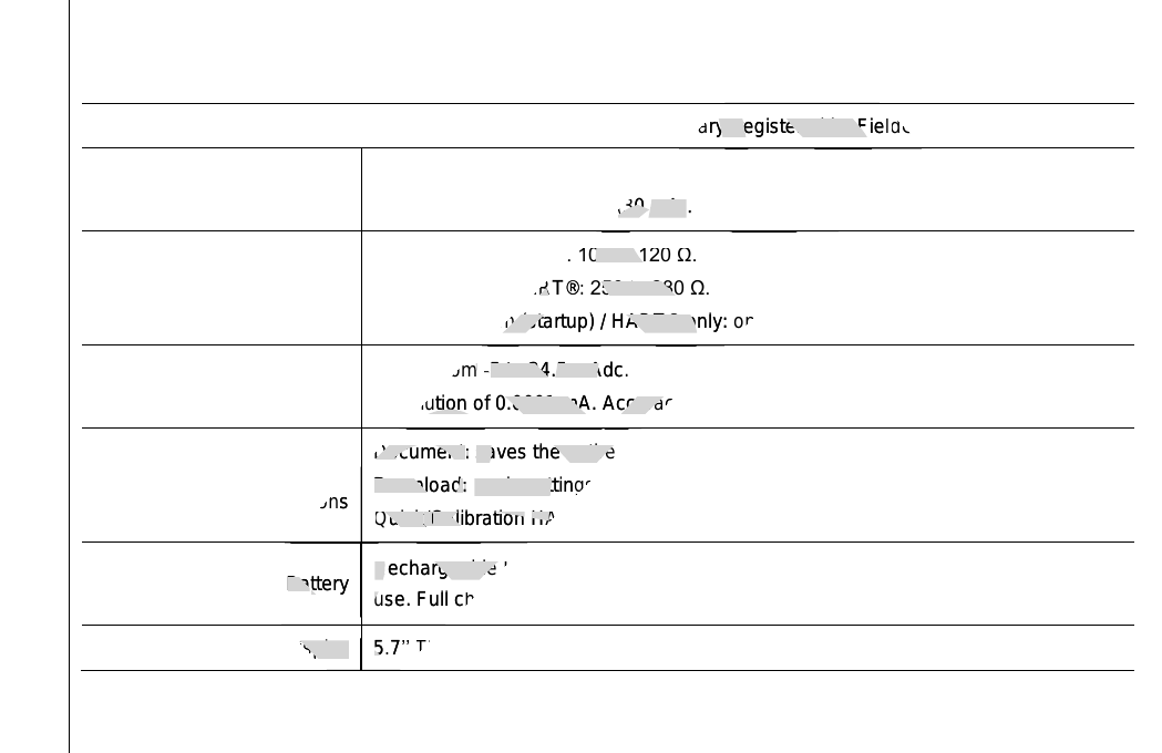
1.2. General Specifications
Full HART® Configurator, with the latest complete DD library, registered by FieldComm Group.
Transmitter Power Supply
(TPS) 24.5 ± 1 V (0 to 24 mA),
with short-circuit protection (30 mA).
Internal Resistor For mA Measurement: 100 to 120 Ω.
For mA input + HART®:250 to 280 Ω.
Safety condition (startup) / HART® only: open.
Input for current
measurement (mA) Range from -5 to 24.5 mAdc.
Resolution of 0.0001 mA. Accuracy of ± 0.02% FS (Full Scale).
Special
software functions
Document:saves the entire configuration tree of the HART® field instrument.
Download:loads settings saved to the instrument with HART® protocol.
Quick/Calibration HART®:easy access to basic HART® commands.
Battery Rechargeable Lithium Polymer with 4200 mAh and up to 12 hours of continuous
use. Full charge in just 3 hours.
Display 5.7’’ TFT VGA touch screen 640 x 480 pixels.
presys
Full HART® Configurator, with the latest complete DD library, registered by Fiel
presys
Full HART® Configurator, with the latest complete DD library, registered by Fiel
d
presys
d
Comm Group.
presys
Comm Group.
presys
circuit protection
presys
circuit protection
(30 mA)
presys
(30 mA)
.
presys
.
presys
ent: 100 to 120 Ω.
presys
ent: 100 to 120 Ω.
+ HART®
presys
+ HART®
:
presys
:
250 to 280 Ω.
presys
250 to 280 Ω.
Safety condition (startup) / HART® only: open
presys
Safety condition (startup) / HART® only: open
presys
Range from
presys
Range from
-
presys
-
5 to 24.5 mAdc.
presys
5 to 24.5 mAdc.
Resolution of 0.0001 mA. Accuracy of ± 0.02% FS (
presys
Resolution of 0.0001 mA. Accuracy of ± 0.02% FS (
presys
Special
presys
Special
ctions
presys
ctions
Document
presys
Document
:
presys
:
saves the entire configuration tree of the HART® field instrument.
presys
saves the entire configuration tree of the HART® field instrument.
Download
presys
Download
:
presys
:
loads settings saved to the instrument with HART® protocol.
presys
loads settings saved to the instrument with HART® protocol.
Quick
presys
Quick
/
presys
/
Quick/Quick
presys
Quick/Quick
Calibration
presys
Calibration
/Calibration/
presys
/Calibration/
HART
presys
HART
presys
presys
Ba
presys
Ba
ttery
presys
ttery
Rechargeable Lithium Polymer
presys
Rechargeable Lithium Polymer
use. Full charge in just 3 hours.
presys
use. Full charge in just 3 hours.
presys
presys
presys
presys
Display
presys
Display
5
presys
5
.
presys
.
7
presys
7
’’
presys
’’
TFT VGA touch
presys
TFT VGA touch
presys
presys
presys
presys
presys
presys
presys
Table of contents
Other Presys Cell Phone manuals


