Presys TA-1200P User manual

®
Q
Y
U
T
A
L
I
E
N
T
M
S
E
Y
G
S
A
T
N
E
A
M
M
Temperature Advanced
Calibrators
TA-1200P
Technical Manual
EM0295-03
presys
presys
presys
presys
Temperature Advanced
presys
Temperature Advanced
Calibrators
presys
Calibrators
Calibrators
presys
Calibrators
TA-1200P
presys
TA-1200P
TA-1200P
presys
TA-1200P

EC Declaration of Conformity
We declare under our sole responsability that the CE marked products, are in conformity
with the essential requirements of the following EC Directives when installed in
accordance with the installation instructions contained in the product documentation:
Series
TA-1200P
Description
Dry-Block Temperature Calibrator
LVD
Low Voltage Directive
2014/35/EC
of the European Parliament and of the Council of 12 December 2006 on
the harmonization of the laws of Member States relating to Electrical Equipment
designed for use within certain voltage limits.
EN 61010-1:2011
Safety requirements for electrical equipment for measurement, control and laboratory
use
EN 61010-2:010
Safety requirements for electrical equipment for measurement, control and laboratory
use -Part 2-010: Particular requirements for laboratory equipment for the heating of
Materials.
EMC directive
2004/108/EC
of the European Parliament and of the Council of 15 December 2004
on the approximation of the laws of the Member States relating to electromagnetic
compatibility and repealing Directive 89/336/EEC
EN 61326-1:2003
Electrical equipment for measurement, control and laboratory use -EMC requirements
São Paulo, 8 September 2016
Vinicius José Gomes Nunes
Antonio Rafael Sito Antunes
CEO
Engineering Manager
presys
presys
We declare under our sole responsability that the CE marked products,
presys
We declare under our sole responsability that the CE marked products,
are in conformity
presys
are in conformity
irectives
presys
irectives
when installe
presys
when installe
d in
presys
d in
installation instructions contained in the product documentation
presys
installation instructions contained in the product documentation
:
presys
:
Block Temperature Calibrator
presys
Block Temperature Calibrator
presys
of the European Parliament and of the Council of 12 December 2006 on
presys
of the European Parliament and of the Council of 12 December 2006 on
presys
harmonization
presys
harmonization
of the laws of Member States relating to Electrical Equipment
presys
of the laws of Member States relating to Electrical Equipment
of the laws of Member States relating to Electrical Equipment
presys
of the laws of Member States relating to Electrical Equipment
presys
designed for use within certain voltage limits
presys
designed for use within certain voltage limits
.
presys
.
Safety requirements for electrical
presys
Safety requirements for electrical
equipment for measurement, control and laboratory
presys
equipment for measurement, control and laboratory
use
presys
use
:010
presys
:010
Safety requirements for electrical equipment for measurement, control and laboratory
presys
Safety requirements for electrical equipment for measurement, control and laboratory
use
presys
use
-
presys
-
Part 2
presys
Part 2
-
presys
-
010: Particular requirements for
presys
010: Particular requirements for
Materials
presys
Materials
.
presys
.
EMC directive
presys
EMC directive
2004/108/EC
presys
2004/108/EC
of the European Parliament and of the Council of 15 December 2004
presys
of the European Parliament and of the Council of 15 December 2004
on the approximation of the laws of the Member States relating to electromagnetic
presys
on the approximation of the laws of the Member States relating to electromagnetic
compatibility and repealing Directive 89/336/EEC
presys
compatibility and repealing Directive 89/336/EEC
EN
presys
EN
61326
presys
61326
-
presys
-
1:2003
presys
1:2003
Electrical equipment for measurement, control and laboratory use
presys
Electrical equipment for measurement, control and laboratory use
S
presys
S
ão Paulo
presys
ão Paulo
,
presys
,
8
presys
8
September 201
presys
September 201
presys
presys
presys
presys
presys

The warranty conditions are available in our sites:
www.presys.com.br/warranty
presys
presys
The warranty conditions are available in our sites:
presys
The warranty conditions are available in our sites:
presys
presys
presys
www.presys.com.br/warranty
presys
www.presys.com.br/warranty
presys
presys
PRESYS Instrumentos e Sistemas TA-1200P
EM0295-03
Table of Contents
1 - Introduction....................................................................................................................1
1.1 -Technical Specifications...........................................................................................2
1.1.1 -Input Technical Specifications...........................................................................3
1.1.2 -Special Software Features................................................................................4
1.2 -Order Code...............................................................................................................4
1.3 - Accessories ..............................................................................................................5
1.4 -Initial Usage..............................................................................................................6
1.5 -Mounting the insert inside the furnace.....................................................................6
1.6 -Instruction for use of the optional Black Body insert...............................................7
1.7 -Parts Identification..................................................................................................10
2 - Calibrator Operation...................................................................................................11
2.1 -Calibrator Menu......................................................................................................12
2.1.1 –Probe Reference.............................................................................................14
2.1.2 -Input Settings...................................................................................................16
2.1.3 -Special Function..............................................................................................20
2.1.4 -Saving Current Configuration (Memory Manager)..........................................21
2.2 -Hart®Configuration.................................................................................................22
2.2.1 -HART®Connections........................................................................................22
2.2.2 -Starting Communication..................................................................................23
2.2.3 -Adjusting the Measurement Range of a HART®Transmitter..........................23
2.2.4 -Adjusting the Measurement Range of a HART®Transmitter with Reference24
2.2.5 -Checking / Adjusting HART®Transmitter mA Output.....................................25
2.3 -Automatic Tasks.....................................................................................................26
2.3.1 -Creating Tasks.................................................................................................26
2.3.2 -Performing Tasks.............................................................................................29
2.3.3 -Viewing Results...............................................................................................29
2.4 -Data-Logger............................................................................................................31
2.5 -Videos.....................................................................................................................32
2.6 -Settings...................................................................................................................32
2.6.1 - System.............................................................................................................32
2.6.2 -Network............................................................................................................34
2.6.3 -Built-in Web Server..........................................................................................34
3 - Safety Instructions......................................................................................................36
4 - Recommendations as regards Accuracy of Measurements .................................36
5 - Calibration (Adjustment)............................................................................................37
5.1 -Input Calibration .....................................................................................................37
5.2 -Probe Calibration....................................................................................................38
5.3 -PID Control Parameters.........................................................................................39
6 - Maintenance.................................................................................................................39
6.1 -Instructions for Hardware Maintenance.................................................................39
presys
....................
presys
....................
...........................
presys
...........................
2
presys
2
................................
presys
................................
...........
presys
...........
3
presys
3
................................
presys
................................
................
presys
................
4
presys
4
................................
presys
................................
...............
presys
...............
4
presys
4
................................
presys
................................
..............
presys
..............
5
presys
5
................................
presys
................................
..............
presys
..............
6
presys
6
................................
presys
................................
................................
presys
................................
.....
presys
.....
6
presys
6
Instruction for use of the optional Black Body insert
presys
Instruction for use of the optional Black Body insert
................................
presys
................................
...............
presys
...............
7
presys
7
................................
presys
................................
................................
presys
................................
..
presys
..
10
presys
10
................................
presys
................................
................................
presys
................................
...
presys
...
11
presys
11
................................
presys
................................
................................
presys
................................
......
presys
......
................................
presys
................................
................................
presys
................................
.............................
presys
.............................
................................
presys
................................
................................
presys
................................
................................
presys
................................
................................
presys
................................
................................
presys
................................
..............................
presys
..............................
Saving Current Configuration (Memory Manager)
presys
Saving Current Configuration (Memory Manager)
................................
presys
................................
................................
presys
................................
................................
presys
................................
................................
presys
................................
Connections
presys
Connections
................................
presys
................................
................................
presys
................................
Starting Communication
presys
Starting Communication
................................
presys
................................
................................
presys
................................
Adjusting the Measurement Range of a HART
presys
Adjusting the Measurement Range of a HART
®
presys
®
Transmi
presys
Transmi
Adjusting the Measurement Range of a HART
presys
Adjusting the Measurement Range of a HART
®
presys
®
Transmitter with Reference
presys
Transmitter with Reference
Checking / Adjusting HART
presys
Checking / Adjusting HART
®
presys
®
Tran
presys
Tran
smitter mA Output
presys
smitter mA Output
Automatic Tasks
presys
Automatic Tasks
................................
presys
................................
................................
presys
................................
Creating Tasks
presys
Creating Tasks
................................
presys
................................
................................
presys
................................
Performing Tasks
presys
Performing Tasks
................................
presys
................................
................................
presys
................................
-
presys
-
Viewing Results
presys
Viewing Results
................................
presys
................................
Data
presys
Data
-
presys
-
Logger
presys
Logger
................................
presys
................................
................................
presys
................................
2.5
presys
2.5
-
presys
-
Videos
presys
Videos
................................
presys
................................
................................
presys
................................
2.6
presys
2.6
-
presys
-
Settings
presys
Settings
................................
presys
................................
................................
presys
................................
2.6.1
presys
2.6.1
-
presys
-
System
presys
System
................................
presys
................................
2.6.2
presys
2.6.2
-
presys
-
Network
presys
Network
................................
presys
................................
2.6.3
presys
2.6.3
-
presys
-
Built
presys
Built
-
presys
-
in Web Server
presys
in Web Server
................................
presys
................................
3
presys
3
-
presys
-
Safety Instructions
presys
Safety Instructions
presys
................................
presys
................................
Recommendations as regards Accuracy of Measurements
presys
Recommendations as regards Accuracy of Measurements
Calibration (Adjustment)
presys
Calibration (Adjustment)
presys
Input Cali
presys
Input Cali
Probe Calibration
presys
Probe Calibration
PRESYS Instruments TA-1200P
Page 1
1 - Introduction
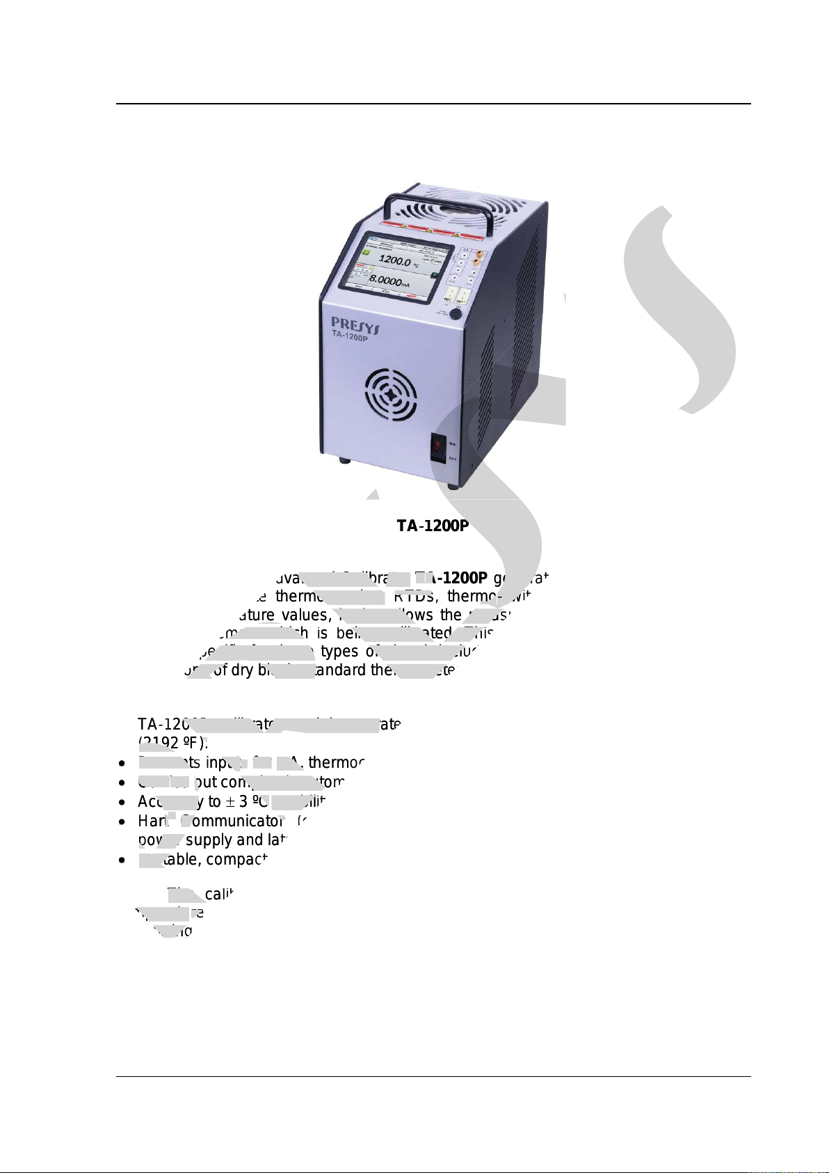
TA-1200P
Temperature Advanced Calibrator TA-1200Pgeneratestemperature in the insert
in order to calibrate thermocouples, RTDs, thermo-switches. Besides providing high
accuracy temperature values, it also allows the measurement of signals generated by
the thermo-element which is being calibrated. This is possible due to an embedded
calibrator specific for these types of signal, including 4-20 mA. Thus, they incorporate
the functions of dry block, standard thermometer and calibrator for RTD, TC and mA.
•TA-1200P calibrator model generatestemperatures from 50 ºC (122 ºF) to 1200 ºC
(2192 ºF).
•Presents inputsfor mA, thermocouples, RTDs and thermo-switches.
•Carries out completely automatic calibrations with or without the use of a computer.
•Accuracy to 3 ºC, stability of 0.2 ºC and resolution of 0.1 ºC.
•Hart®Communicator (optional) with internal resistance configurable, transmitter
power supply and latest DD as option.
•Portable, compact, provides interchangeable inserts and carrying case.
The calibrator also provides an input for an external probe to perform the
temperature measurement from a standard sensor (optional) inserted in the same
measuring zone of the sensor to be calibrated, increasing the accuracy and decreasing
loading effects. The standard sensor calibration curve follows the parameterization of
ITS-90.
It presentsa wide variety of programming resources, allowing the performance of
automatic calibrations.In this case, the sensor is placed in the insert and its electrical
presys
presys
T
presys
T
A
presys
A
-
presys
-
1200P
presys
1200P
Temperature Advanced Calibrator
presys
Temperature Advanced Calibrator
T
presys
T
A
presys
A
-
presys
-
1200
presys
1200
P
presys
P
generate
presys
generate
in order to calibrate thermocouples,
presys
in order to calibrate thermocouples,
RTDs
presys
RTDs
, thermo
presys
, thermo
-
presys
-
switches. Besides providing high
presys
switches. Besides providing high
accuracy temperature values, it also allows the measurement of signals generated by
presys
accuracy temperature values, it also allows the measurement of signals generated by
element which
presys
element which
is
presys
is
being calibrated. This is possible due to
presys
being calibrated. This is possible due to
calibrator specific for these types of signal, including 4
presys
calibrator specific for these types of signal, including 4
the functions of dry block, standard thermometer and calibrator for RTD, TC and mA.
presys
the functions of dry block, standard thermometer and calibrator for RTD, TC and mA.
TA
presys
TA
-
presys
-
1200P calibrator model generate
presys
1200P calibrator model generate
(2192
presys
(2192
ºF).
presys
ºF).
•
presys
•
Present
presys
Present
s
presys
s
input
presys
input
s
presys
s
for
presys
for
mA,
presys
mA,
thermocouples,
presys
thermocouples,
•
presys
•
Carr
presys
Carr
ies
presys
ies
out completely automatic calibrations with or without the use of a computer.
presys
out completely automatic calibrations with or without the use of a computer.
•
presys
•
Accuracy to
presys
Accuracy to
presys
3 ºC
presys
3 ºC
, stability of 0.2 ºC and resolution of 0.1 ºC
presys
, stability of 0.2 ºC and resolution of 0.1 ºC
•
presys
•
Hart
presys
Hart
®
presys
®
Communicator
presys
Communicator
(optional) with internal resistance configurable, transmitter
presys
(optional) with internal resistance configurable, transmitter
power supply and latest DD as option.
presys
power supply and latest DD as option.
•
presys
•
Portable, compact, provides interchangeable inserts and carrying case.
presys
Portable, compact, provides interchangeable inserts and carrying case.
The calibrator also provides an input for an external probe to perform the
presys
The calibrator also provides an input for an external probe to perform the
temperatu
presys
temperatu
re
presys
re
presys
measurement
presys
measurement
measuring zone of the sensor to be calibrated, increasing the accuracy and decreasing
presys
measuring zone of the sensor to be calibrated, increasing the accuracy and decreasing
loading effects. The standard sensor calibration curve follows the parameterization of
presys
loading effects. The standard sensor calibration curve follows the parameterization of

PRESYS Instruments TA-1200P
Page 2
terminals are connected to the embedded calibrator. The operator defines the calibration
points and the number of repetitions (task), then the process is started and all the
sequence is automatically accomplished. After completing the task, a Calibration Report
is issued and it can be printed directly in a USB connected printer or can be generated a
PDF document.
It has HART® communication for reading and setting parameters of field devices
that have this protocol.
TA-1200Phasalso many other features, such as:
•RTD input for 2, 3 and 4 wires. Table IEC 60751, JIS or Callendar-Van Dusen
user-configurable. Engineering units configurable to °C, °F and K.
•Built in Web Server, Ethernet communication.
•USB port for software/firmware upgrade.
•HART®Communication Protocol (optional).
•The electric signal calibrator is independent from the dry block function.
•Display indication when the temperature reaches the desired value.
•5.7 inches touchscreen display that eases the operation and configuration of the
calibrator.
•Thermo-element reading scaled to ITS-90 or IPTS-68.
•Internal regulated 24 Vdc power supply for 2-wire transmitters.
•Independent circuit for over-temperature protection and safety.
•Insert to choose, carrying case, handles and test leads included. If the insert is not
specified, it will be provided the insert type IN06.
1.1 -Technical Specifications
TA-1200P
Operating Range
50 to 1200 °C
Display Accuracy
2.2 °C
Resolution
0.1 ºC
Stability
0.1ºC
Radial Uniformity
(homogeneity)
0.05 ºC @ 50 ºC
0.15 ºC @ 650 ºC
0.20 ºC @1100 ºC
Axial Uniformity
(homogeneity) (20 mm)
0.15 ºC @ 50 ºC
0.25 ºC @ 650 ºC
0.25 ºC @1100 ºC
Heating Time
100 min (100 ºC to 1200 ºC)
Cooling Time
5 h (1200 ºC to 200 ºC)
Electric Power
800 W
Well Diameter x Depth
Ø 34 mm x 130 mm
Weight
12.6 kg
Dimension (HxWxD)
350 x 205 x 325 mm
presys
It has HART® communication for reading and setting parameters of field devices
presys
It has HART® communication for reading and setting parameters of field devices
RTD input for 2, 3 and 4 wires. Table IEC 60751, JIS or
presys
RTD input for 2, 3 and 4 wires. Table IEC 60751, JIS or
Callendar
presys
Callendar
-
presys
-
Callendar-Callendar
presys
Callendar-Callendar
Van
presys
Van
Dusen
presys
Dusen
Engineering units configurable to °C, °F
presys
Engineering units configurable to °C, °F
and
presys
and
K.
presys
K.
The electric signal calibrator is independent from the dry bloc
presys
The electric signal calibrator is independent from the dry bloc
k function.
presys
k function.
when the temperature reaches the desired value.
presys
when the temperature reaches the desired value.
that eases the operation and configuration of the
presys
that eases the operation and configuration of the
element reading scaled to ITS
presys
element reading scaled to ITS
-
presys
-
90 or IPTS
presys
90 or IPTS
-
presys
-
68.
presys
68.
supply for 2
presys
supply for 2
-
presys
-
wire transmitters.
presys
wire transmitters.
temperature protection and safety.
presys
temperature protection and safety.
Insert to choose, carrying case,
presys
Insert to choose, carrying case,
handles
presys
handles
and test leads included. If the insert is not
presys
and test leads included. If the insert is not
specified, it will be provided the insert type
presys
specified, it will be provided the insert type
IN
presys
IN
06.
presys
06.
Technical Sp
presys
Technical Sp
ecifications
presys
ecifications
Operating Range
presys
Operating Range
presys
presys
presys
presys
presys
Display
presys
Display
Accuracy
presys
Accuracy
presys
presys
presys
presys
Resolution
presys
Resolution
presys
presys
presys
presys
presys
S
presys
S
tability
presys
tability
presys
presys
presys
presys
Radial Uniformity
presys
Radial Uniformity
(homogeneity)
presys
(homogeneity)
presys
presys
presys
presys
presys
Axial
presys
Axial
Uniformity
presys
Uniformity
(homogeneity)
presys
(homogeneity)
(20 mm)
presys
(20 mm)
presys
presys
presys
presys
Heating
presys
Heating
Time
presys
Time
presys
presys
Cooling
presys
Cooling
Time
presys
Time
presys
Electric Power
presys
Electric Power
presys
presys
ameter x Depth
presys
ameter x Depth
presys

PRESYS Instruments TA-1200P
Page 3
1.1.1 - Input Technical Specifications
Input Ranges
Resolution
Accuracy
Remarks
millivolt
-150 mV to 150 mV
0.001 mV
0.01 % FS*
R
input
> 10 M
150 mV to 2450 mV
0.01 mV
0.02 % FS
auto-ranging
mA
-1 mA to 24.5 mA 0.0001 mA 0.01% FS Rinput < 120
resistance
0 to 400
400 to 2500 0.01
0.01
0.01 % FS
0.03 % FS
Excitation current
0.85 mA
auto-ranging
Pt-100
-200 to 850
C / -328 to 1562
F
0.01
C / 0.01
F
0.1
C /
0.2
F
IEC 60751
Pt-1000
-200 to 400
C / -328 to 752
F
0.1
C / 0.1
F
0.1
C /
0.2
F
IEC 60751
Cu-10
-200 to 260 C / -328 to 500 F0.1 C / 0.1 F2.0 C / 4.0 FMinco 16-9
Ni-100
-60 to 250
C / -76 to 482
F
0.1
C / 0.1
F
0.2
C /
0.4
F
DIN-43760
TC-J
-210 to 1200
C / -346 to 2192
F
0.1
C / 0.1
F
0.2
C /
0.4
F
IEC 60584
TC-K
-270 to -150
C / -454 to -238
F
0.1
C / 0.1
F
0.5
C /
1.0
F
IEC 60584
TC-K
-150 to 1370
C / -238 to 2498
F
0.1
C / 0.1
F
0.2
C /
0.4
F
IEC 60584
TC-T
-260 to -200 C / -436 to -328 F0.1 C / 0.1 F0.6 C / 1.2 FIEC 60584
TC-T
-200 to -75 C / -328 to -103 F0.1 C / 0.1 F0.4 C / 0.8 FIEC 60584
TC-T
-75 to 400 C / -103 to 752 F0.1 C / 0.1 F0.2 C / 0.4 FIEC 60584
TC-B
50 to 250 C / 122 to 482 F0.1 C / 0.1 F2.5 C / 5.0 FIEC 60584
TC-B
250 to 500
C / 482 to 932
F
0.1
C / 0.1
F
1.5
C /
3.0
F
IEC 60584
TC-B
500 to 1200 C / 932 to 2192 F0.1 C / 0.1 F1.0 C / 2.0 FIEC 60584
TC-B
1200 to 1820 C / 2192 to 3308 F0.1 C / 0.1 F0.7 C / 1.4 FIEC 60584
TC-R
-50 to 300
C / -58 to 572
F
0.1
C / 0.1
F
1.0
C /
2.0
F
IEC 60584
TC-R
300 to 1760
C / 572 to 3200
F
0.1
C / 0.1
F
0.7
C /
1.4
F
IEC 60584
TC-S
-50 to 300 C / -58 to 572 F0.1 C / 0.1 F1.0 C / 2.0 FIEC 60584
TC-S
300 to 1760
C / 572 to 3200
F
0.1
C / 0.1
F
0.7
C /
1.4
F
IEC 60584
TC-E
-270 to -150 C / -454 to -238 F0.1 C / 0.1 F0.3 C / 0.6 FIEC 60584
TC-E
-150 to 1000
C / -238 to 1832
F
0.1
C / 0.1
F
0.1
C /
0.2
F
IEC 60584
TC-N
-260 to -200 C / -436 to -328 F0.1 C / 0.1 F1.0 C / 2.0 FIEC 60584
TC-N
-200 to -20 C / -328 to -4 F0.1 C / 0.1 F0.4 C / 0.8 FIEC 60584
TC-N
-20 to 1300 C / -4 to 2372 F0.1 C / 0.1 F0.2 C / 0.4 FIEC 60584
TC-L
-200 to 900
C / -328 to 1652
F
0.1
C / 0.1
F
0.2
C /
0.4
F
DIN-43710
TC-C
0 to 1500
C / 32 to 2732
F
0.1
C / 0.1
F
0.5
C /
1.0
F
W5Re / W26Re
TC-C
1500 to 2320
C / 2732 to 4208
F
0.1
C / 0.1
F
0.7
C /
1.4
F
W5Re / W 26Re
*FS = Full Scale
Accuracy values are valid within one year and temperature range of 20 to 26 °C.
Outside these limits add 0.001 % FS / C taking 23 °C as the reference temperature.
For thermocouples, using the internal cold junction compensation add a cold junction
compensation error of 0.2 C or 0.4 F max.
presys
auto
presys
auto
-
presys
-
ranging
presys
ranging
R
presys
R
inpu
presys
inpu
t
presys
t
< 120
presys
< 120
presys
presys
Excitation current
presys
Excitation current
0.85
presys
0.85
mA
presys
mA
auto
presys
auto
-
presys
-
ranging
presys
ranging
presys
presys
presys
presys
C /
presys
C /
presys
0.2
presys
0.2
presys
F
presys
F
IEC 60751
presys
IEC 60751
presys
presys
presys
presys
presys
0.1
presys
0.1
presys
C /
presys
C /
presys
0.2
presys
0.2
presys
F
presys
F
IEC 60751
presys
IEC 60751
presys
presys
presys
presys
presys
presys
presys
2.0
presys
2.0
presys
C /
presys
C /
presys
4.0
presys
4.0
presys
F
presys
F
Minco 16
presys
Minco 16
-
presys
-
9
presys
9
presys
presys
presys
presys
presys
presys
presys
0.2
presys
0.2
presys
C /
presys
C /
presys
0.4
presys
0.4
presys
F
presys
F
DIN
presys
DIN
-
presys
-
43760
presys
43760
presys
presys
presys
presys
presys
presys
presys
C / 0.1
presys
C / 0.1
presys
F
presys
F
presys
0.2
presys
0.2
presys
C /
presys
C /
presys
0.4
presys
0.4
presys
F
presys
F
IEC 60584
presys
IEC 60584
presys
presys
presys
presys
presys
presys
presys
presys
presys
C / 0.1
presys
C / 0.1
presys
F
presys
F
presys
0.5
presys
0.5
presys
C /
presys
C /
presys
1.0
presys
1.0
presys
F
presys
F
IEC 60584
presys
IEC 60584
presys
presys
presys
presys
presys
presys
presys
C / 0.1
presys
C / 0.1
presys
F
presys
F
presys
0.2
presys
0.2
presys
C /
presys
C /
presys
0.4
presys
0.4
presys
F
presys
F
IEC 60584
presys
IEC 60584
presys
presys
0.1
presys
0.1
presys
C / 0.1
presys
C / 0.1
presys
F
presys
F
presys
0.6
presys
0.6
presys
C /
presys
C /
presys
1.2
presys
1.2
presys
F
presys
F
IEC 60584
presys
IEC 60584
presys
presys
presys
presys
presys
presys
presys
0.1
presys
0.1
presys
C / 0.1
presys
C / 0.1
presys
F
presys
F
presys
0.4
presys
0.4
presys
C /
presys
C /
presys
0.8
presys
0.8
presys
F
presys
F
IEC 60584
presys
IEC 60584
presys
presys
presys
0.1
presys
0.1
presys
C / 0.1
presys
C / 0.1
presys
F
presys
F
presys
0.2
presys
0.2
presys
C /
presys
C /
presys
0.4
presys
0.4
presys
F
presys
F
IEC 60584
presys
IEC 60584
presys
presys
presys
0.1
presys
0.1
presys
C / 0.1
presys
C / 0.1
presys
F
presys
F
presys
2.5
presys
2.5
presys
C /
presys
C /
presys
5.0
presys
5.0
presys
F
presys
F
presys
presys
presys
presys
presys
presys
presys
presys
C / 482 to 932
presys
C / 482 to 932
presys
F
presys
F
0.1
presys
0.1
presys
C / 0.1
presys
C / 0.1
presys
F
presys
F
presys
1.5
presys
1.5
presys
C /
presys
C /
presys
3.0
presys
3.0
presys
presys
C / 932 to 2192
presys
C / 932 to 2192
presys
F
presys
F
0.1
presys
0.1
presys
C / 0.1
presys
C / 0.1
presys
F
presys
F
presys
1.0
presys
1.0
presys
C /
presys
C /
presys
2.0
presys
2.0
presys
presys
C / 2192 to 3308
presys
C / 2192 to 3308
presys
F
presys
F
0.1
presys
0.1
presys
C / 0.1
presys
C / 0.1
presys
F
presys
F
presys
0.7
presys
0.7
presys
C /
presys
C /
presys
presys
58 to 572
presys
58 to 572
presys
F
presys
F
0.1
presys
0.1
presys
C / 0.1
presys
C / 0.1
presys
F
presys
F
presys
1.0
presys
1.0
presys
presys
presys
presys
presys
presys
presys
presys
presys
C / 572 to 3200
presys
C / 572 to 3200
presys
F
presys
F
0.1
presys
0.1
presys
C / 0.1
presys
C / 0.1
presys
F
presys
F
presys
0.7
presys
0.7
presys
presys
50 to 300
presys
50 to 300
presys
C /
presys
C /
-
presys
-
58 to 572
presys
58 to 572
presys
F
presys
F
0.1
presys
0.1
presys
C / 0.1
presys
C / 0.1
presys
F
presys
F
presys
presys
presys
presys
presys
presys
presys
300 to 1760
presys
300 to 1760
presys
C / 572 to 3200
presys
C / 572 to 3200
presys
F
presys
F
0.1
presys
0.1
presys
C / 0.1
presys
C / 0.1
presys
F
presys
F
presys
270 to
presys
270 to
-
presys
-
150
presys
150
presys
C /
presys
C /
-
presys
-
454 to
presys
454 to
-
presys
-
238
presys
238
presys
F
presys
F
0.1
presys
0.1
presys
C / 0.1
presys
C / 0.1
presys
presys
presys
presys
-
presys
-
150 to 1000
presys
150 to 1000
presys
C /
presys
C /
-
presys
-
238 to 1832
presys
238 to 1832
presys
F
presys
F
presys
0.1
presys
0.1
presys
C / 0.1
presys
C / 0.1
presys
-
presys
-
N
presys
N
-
presys
-
260 to
presys
260 to
-
presys
-
200
presys
200
presys
C /
presys
C /
-
presys
-
436 to
presys
436 to
-
presys
-
328
presys
328
presys
F
presys
F
0.1
presys
0.1
presys
presys
presys
presys
presys
presys
presys
TC
presys
TC
-
presys
-
N
presys
N
-
presys
-
200 to
presys
200 to
-
presys
-
20
presys
20
presys
C /
presys
C /
-
presys
-
328 to
presys
328 to
-
presys
-
4
presys
4
presys
F
presys
F
0.1
presys
0.1
presys
TC
presys
TC
-
presys
-
N
presys
N
-
presys
-
20 to 1300
presys
20 to 1300
presys
C /
presys
C /
-
presys
-
4 to 2372
presys
4 to 2372
presys
F
presys
F
TC
presys
TC
-
presys
-
L
presys
L
-
presys
-
200 to 900
presys
200 to 900
presys
C /
presys
C /
-
presys
-
328 to 1652
presys
328 to 1652
presys
F
presys
F
presys
presys
presys
presys
TC
presys
TC
-
presys
-
C
presys
C
0 to 1500
presys
0 to 1500
presys
C / 32 to 2732
presys
C / 32 to 2732
presys
F
presys
F
presys
presys
presys
presys
presys
TC
presys
TC
-
presys
-
C
presys
C
1500 to 2320
presys
1500 to 2320
presys
C / 2732 to 4208
presys
C / 2732 to 4208
presys
presys
presys
presys
presys
presys
*FS = Full Scale
presys
*FS = Full Scale
Ac
presys
Ac
curacy values are valid within one
presys
curacy values are valid within one
Outside these limits add 0.001 % FS /
presys
Outside these limits add 0.001 % FS /
For thermocouples, using the internal cold junction compensation add a cold junction
presys
For thermocouples, using the internal cold junction compensation add a cold junction
presys
compensation error of
presys
compensation error of

PRESYS Instruments TA-1200P
Page 4
1.1.2 - Special Software Features
-Special Function:
SCALE:makes the scaling of mA input.
-Memory Manager: stores configuration types predefined by the user.
-Automated Tasks: creating of calibration work orders and automatic execution of
calibration services, storage of data and reporting.
-Data Logger:monitoring of input or output signals, storage and visualization of
data in chart or table.
-Videos: storage and viewing videos on the calibrator screen.
1.2 -Order Code
Notes:
*Changes can be introduced in the instrument, altering specifications in this manual.
* HART®is a FieldComm Group trademark.
presys
tores configuration types predefined by the user.
presys
tores configuration types predefined by the user.
calibration work orders and automatic execution of
presys
calibration work orders and automatic execution of
, storage and visualization of
presys
, storage and visualization of
he calibrator screen.
presys
he calibrator screen.
presys
Notes:
presys
Notes:
*
presys
*
Changes can be introduced in the instrument, altering specifications in this manual.
presys
Changes can be introduced in the instrument, altering specifications in this manual.
* HART
presys
* HART
®
presys
®
is a
presys
is a
Field
presys
Field
Comm Group
presys
Comm Group
PRESYS Instruments TA-1200P
Page 5
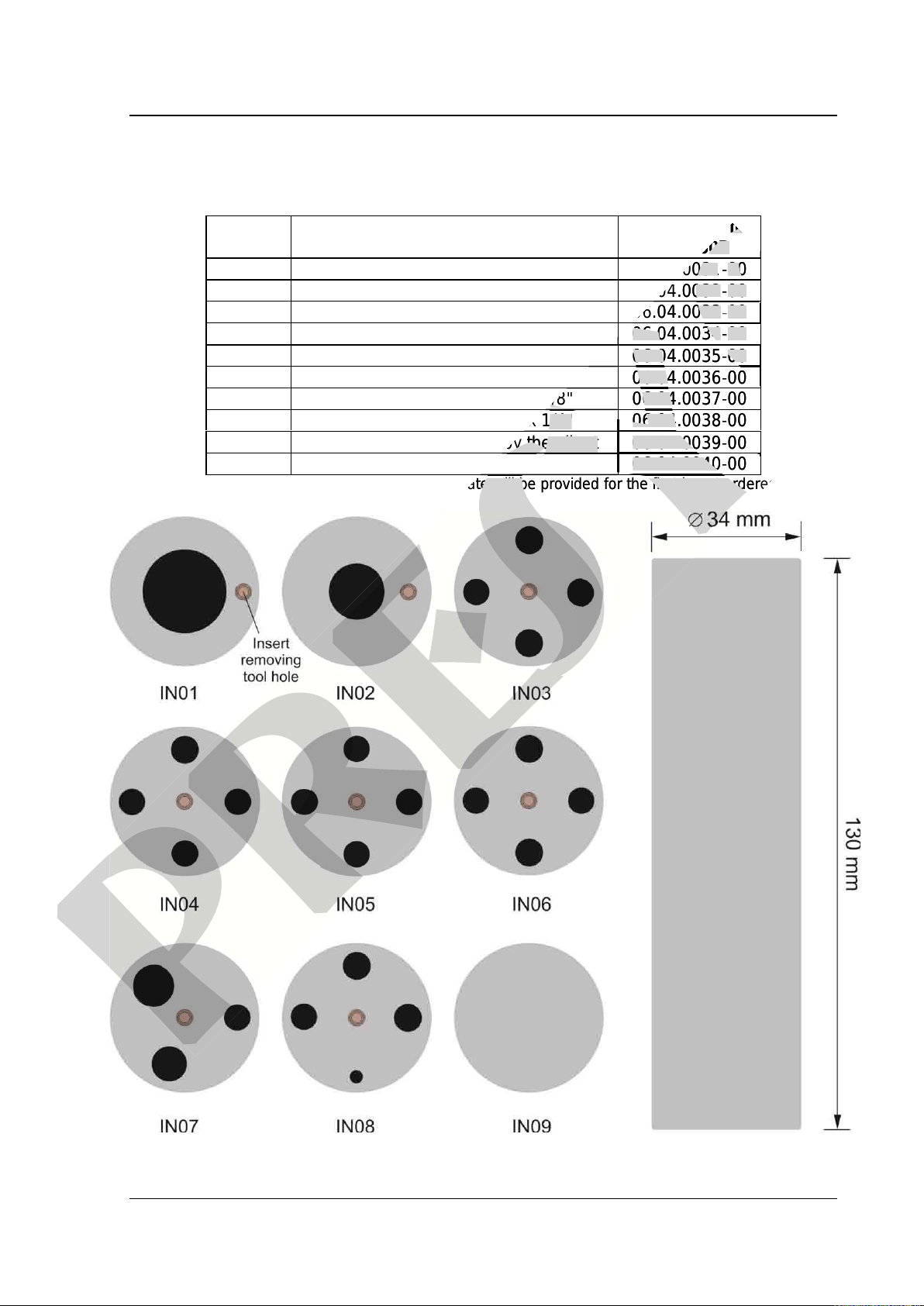
1.3 -Accessories
•Dry Block Insert:
Inserts Holes
Order Code for
TA-1200P
IN01
1 x 3/4"
06.04.0031-00
IN02
1 x 1/2"
06.04.0032-00
IN03
1 x 6.0mm and 3 x 1/4"
06.04.0033-00
IN04
3 x 6.0mm and 1 x 1/4"
06.04.0034-00
IN05
4 x 6.0mm
06.04.0035-00
IN06
2 x 6.0mm and 2 x 1/4"
06.04.0036-00
IN07
1 x 6.0mm, 1 x 8.0mm and 1 x 3/8"
06.04.0037-00
IN08
1 x 6.0mm, 1 x 3.0mm and 2 x 1/4"
06.04.0038-00
IN09
Without hole, to be drilled by the client
06.04.0039-00
IN10
Others, under ordering
06.04.0040-00
Note: When asked, the calibration certificate will be provided for the first insert ordered.
Fig. 01 -Inserts
presys
Order Code for
presys
Order Code for
120
presys
120
0P
presys
0P
presys
06.04.0031
presys
06.04.0031
-
presys
-
00
presys
00
presys
presys
presys
06.04.0032
presys
06.04.0032
-
presys
-
00
presys
00
presys
presys
presys
06.04.0033
presys
06.04.0033
-
presys
-
00
presys
00
presys
presys
presys
06.04.0034
presys
06.04.0034
-
presys
-
00
presys
00
presys
presys
presys
presys
06.04.0035
presys
06.04.0035
-
presys
-
00
presys
00
presys
presys
presys
presys
presys
presys
06.04.0036
presys
06.04.0036
-
presys
-
00
presys
00
presys
presys
presys
presys
presys
presys
1 x 6.0mm, 1 x 8.0mm and 1 x 3/8"
presys
1 x 6.0mm, 1 x 8.0mm and 1 x 3/8"
06.04.0037
presys
06.04.0037
-
presys
-
00
presys
00
presys
presys
presys
presys
presys
presys
1 x 6.0mm, 1 x 3.0mm and 2 x 1/4"
presys
1 x 6.0mm, 1 x 3.0mm and 2 x 1/4"
06.04.0038
presys
06.04.0038
-
presys
-
00
presys
00
presys
presys
presys
presys
presys
presys
Without hole, to be drilled by the client
presys
Without hole, to be drilled by the client
06.04.0039
presys
06.04.0039
-
presys
-
00
presys
00
presys
presys
presys
presys
presys
presys
06.04.0040
presys
06.04.0040
-
presys
-
00
presys
00
presys
presys
presys
presys
presys
presys
presys
presys
presys
presys
presys
Note: When asked, the calibration certificate will be provided for the first insert ordered.
presys
Note: When asked, the calibration certificate will be provided for the first insert ordered.
presys
PRESYS Instruments TA-1200P
Page 6
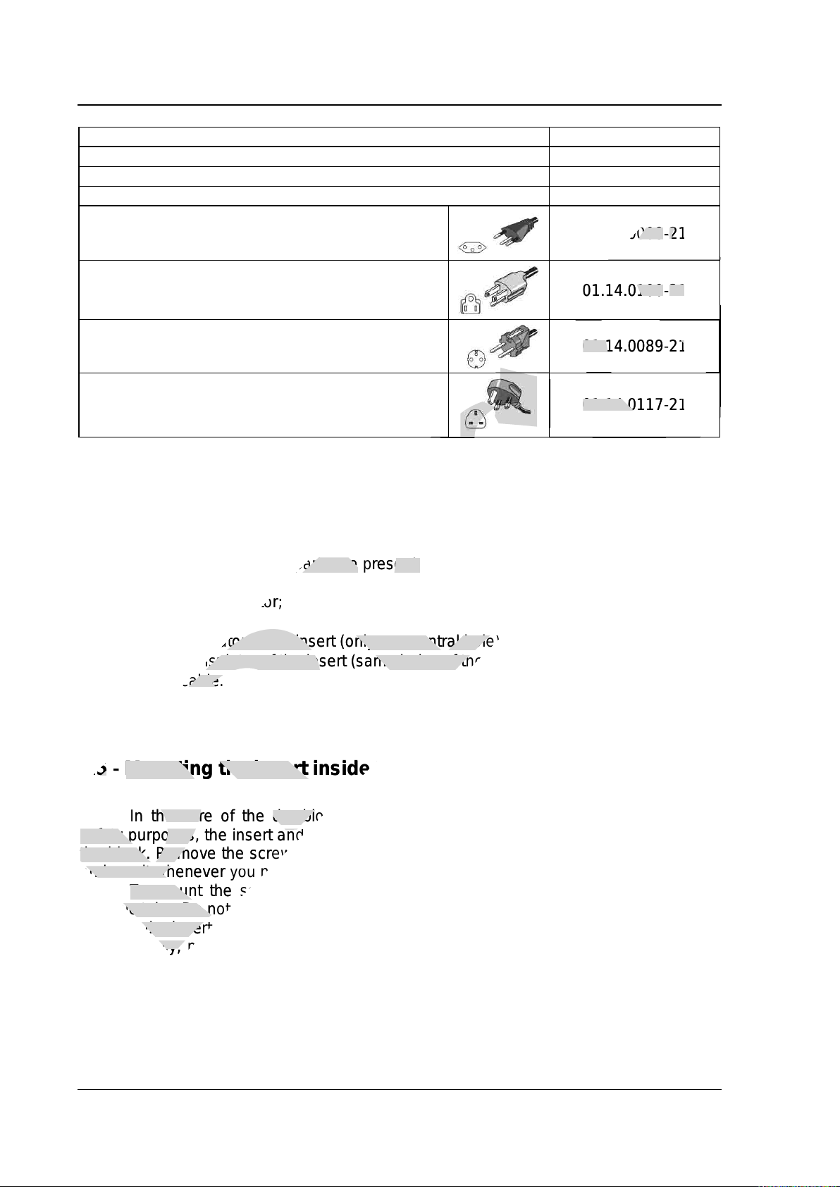
Description
Order Code
Soft Carrying Case for TA-1200P model
06.01.1032-00
Insert Extractor
02.06.0087-20
Lead Cable Kit
06.07.0018-00
Power Cable Type J –Brazil 01.14.0008-21
Power Cable Type B –US 01.14.0100-21
Power Cable Type F –Europe Universal 01.14.0089-21
Power Cable Type J –UK 01.14.0117-21
1.4 -Initial Usage
Identify if the following parts are present:
•TA-1200P Calibrator;
•Metallic insert;
•Inferior insulator of the insert (only one central hole);
•Superior insulator of the insert (same holes of the metallic insert);
•Power cable.
1.5 - Mounting the insert inside the furnace
In the core of the dry block TA-1200P there is a ceramic tube. Therefore, for
safety purposes, the insert and the insulators are separated. Asupport is sent to protect
the block. Remove the screws indicated by the arrows and remove the support. Store it
and use it whenever you need to transport the dry block.
To mount the set, one should first slide gently the inferior insulator inside the
ceramic tube. Do not let it free, slide it inside the tube. Afterwards, hold the metallic insert
by using the insert extractor tool and lower it inside the ceramic tube.
Finally, place the superior insulator above the insert. Note that the sensor to be
tested should go through the insulator and the metallic insert to achieve a correct
temperature measurement.
presys
01.14.0008
presys
01.14.0008
-
presys
-
21
presys
21
presys
presys
01.14.0100
presys
01.14.0100
-
presys
-
21
presys
21
presys
presys
presys
presys
presys
01.14.0089
presys
01.14.0089
-
presys
-
21
presys
21
presys
presys
presys
presys
presys
presys
presys
01.14.0117
presys
01.14.0117
-
presys
-
21
presys
21
presys
presys
presys
presys
presys
presys
presys
presys
presys
presys
presys
presys
presys
Identify if the following parts are
presys
Identify if the following parts are
present:
presys
present:
1200P Calibrator;
presys
1200P Calibrator;
Inferior insulator of the insert (only one central hole);
presys
Inferior insulator of the insert (only one central hole);
Superior insulator of the insert (same holes of the metallic insert);
presys
Superior insulator of the insert (same holes of the metallic insert);
Power cable.
presys
Power cable.
1.
presys
1.
5
presys
5
-
presys
-
Mounting the insert inside the furnace
presys
Mounting the insert inside the furnace
In the core of the
presys
In the core of the
dry block TA
presys
dry block TA
safety purposes, the insert and the insulators are separated.
presys
safety purposes, the insert and the insulators are separated.
the block. Remove the screws indicated by the arrows and remove the support. Store it
presys
the block. Remove the screws indicated by the arrows and remove the support. Store it
and use it whenever
presys
and use it whenever
you
presys
you
need to transport the dry
presys
need to transport the dry
To mount the set, one should first slide gently the inferior insulator inside the
presys
To mount the set, one should first slide gently the inferior insulator inside the
ceramic tube. Do not let it free, slide it inside the tube. Afterwards, hold the metallic insert
presys
ceramic tube. Do not let it free, slide it inside the tube. Afterwards, hold the metallic insert
by using the insert extractor tool and
presys
by using the insert extractor tool and
presys
Finally, place the superior insulator above the insert. Note that the sensor to be
presys
Finally, place the superior insulator above the insert. Note that the sensor to be
tested should go through the insulator and the metallic insert to achieve a correct
presys
tested should go through the insulator and the metallic insert to achieve a correct
PRESYS Instruments TA-1200P
Page 7
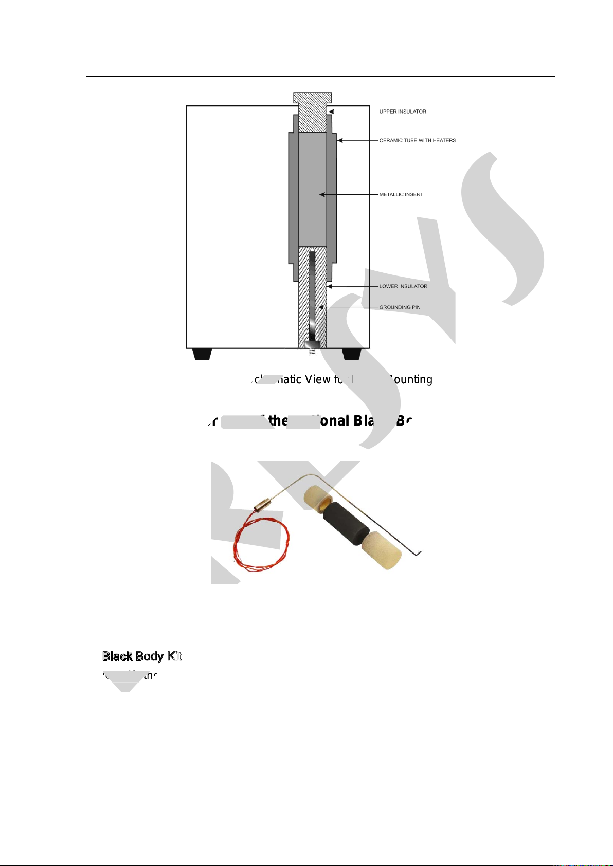
Fig 2 -Schematic View for Insert Mounting
1.6 -Instruction for use of the optional Black Body insert
Fig 3 - Black Body Kit
Black Body Kit
Identify the following parts and proceed to the mounting as explained:
•Cylindrical Thermal insulator –Mounted in the lower part of the pit of the
furnace.
•Metallic Insert type Black Body cavity –Must be introduced in the pit joined
with a thermocouple type N mounted laterally.
presys
presys
Schema
presys
Schema
tic View for
presys
tic View for
Insert Mounting
presys
Insert Mounting
Instruction for use of the optional Black Body insert
presys
Instruction for use of the optional Black Body insert
presys
B
presys
B
presys
l
presys
l
presys
a
presys
a
presys
c
presys
c
presys
k
presys
k
presys
B
presys
B
presys
o
presys
o
presys
d
presys
d
presys
y
presys
y
presys
presys
K
presys
K
presys
i
presys
i
presys
presys
Identify the following parts and proceed to the mounting as explained:
presys
Identify the following parts and proceed to the mounting as explained:

PRESYS Instruments TA-1200P
Page 8
Careful when entering the thermocouple in the cavity to not force the fragile
ceramic wall pit.
•Ring-shaped cylindrical Insulator -mounted on top of the pit of the furnace
Note that the position of the slit of insulation should match the type N
thermocouple sheath laterally.
•Connect the terminals of the thermocouple type N to the auxiliary input side of
the furnace TA-1200P and set the reading of the input to N type thermocouple
(CJC internal).
The combination constitutes an excellent mounted cavity blackbody with
emissivity of (0,95 0,02) and an effective target of Ø 20 mm well suited for calibration of
infrared thermometers.
Align the thermometer to be calibrated with a black body cavity in the furnace
in a vertical position.
Observe the distance of the infrared thermometer to be calibrated against the
background of the black body cavity and the size of the actual target (Ø 20 mm) as
specified in the technical manual of the thermometer.
Remember that the area targeted by the thermometer to be calibrated must be
less than or equal to the effective target spot size of the blackbody in order to not
introduce measurement errors.
Use the certificate of calibration of the thermocouple type N to correct the
readings from the input of the calibrator and comparing the reading of the thermometer.
presys
Note that the position of the slit of insulation should match the type N
presys
Note that the position of the slit of insulation should match the type N
Connect the terminals of the thermocouple type N to the auxiliary input side of
presys
Connect the terminals of the thermocouple type N to the auxiliary input side of
1200P and set the reading of the input to N type thermocouple
presys
1200P and set the reading of the input to N type thermocouple
The combination constitutes an excellent mounted cavity blackbody with
presys
The combination constitutes an excellent mounted cavity blackbody with
Ø 20 mm
presys
Ø 20 mm
well suited for calibration of
presys
well suited for calibration of
to be calibrated with a black body cavity in the furnace
presys
to be calibrated with a black body cavity in the furnace
infrared thermometer
presys
infrared thermometer
to be calibrated against the
presys
to be calibrated against the
background of the black body cavity and the size of the ac
presys
background of the black body cavity and the size of the ac
tual target (Ø 20 mm) as
presys
tual target (Ø 20 mm) as
specified in the technical manual of the
presys
specified in the technical manual of the
thermometer
presys
thermometer
.
presys
.
Remember that the area targeted by the
presys
Remember that the area targeted by the
thermometer
presys
thermometer
to be calibrated must be
presys
to be calibrated must be
less than or equal to the effective target spot size of the blackbody in order to not
presys
less than or equal to the effective target spot size of the blackbody in order to not
rement errors
presys
rement errors
.
presys
.
Use the certificate of calibration of the thermocouple type N to correct the
presys
Use the certificate of calibration of the thermocouple type N to correct the
readings from the input of the calibrator and comparing the reading of the
presys
readings from the input of the calibrator and comparing the reading of the

PRESYS Instruments TA-1200P
Page 9
Fig 4 -Schematic view for mounting of the black body cavity
presys
presys
Fig 4
presys
Fig 4
-
presys
-
Schematic view for mounting of the black body cavity
presys
Schematic view for mounting of the black body cavity
PRESYS Instruments TA-1200P
Page 10
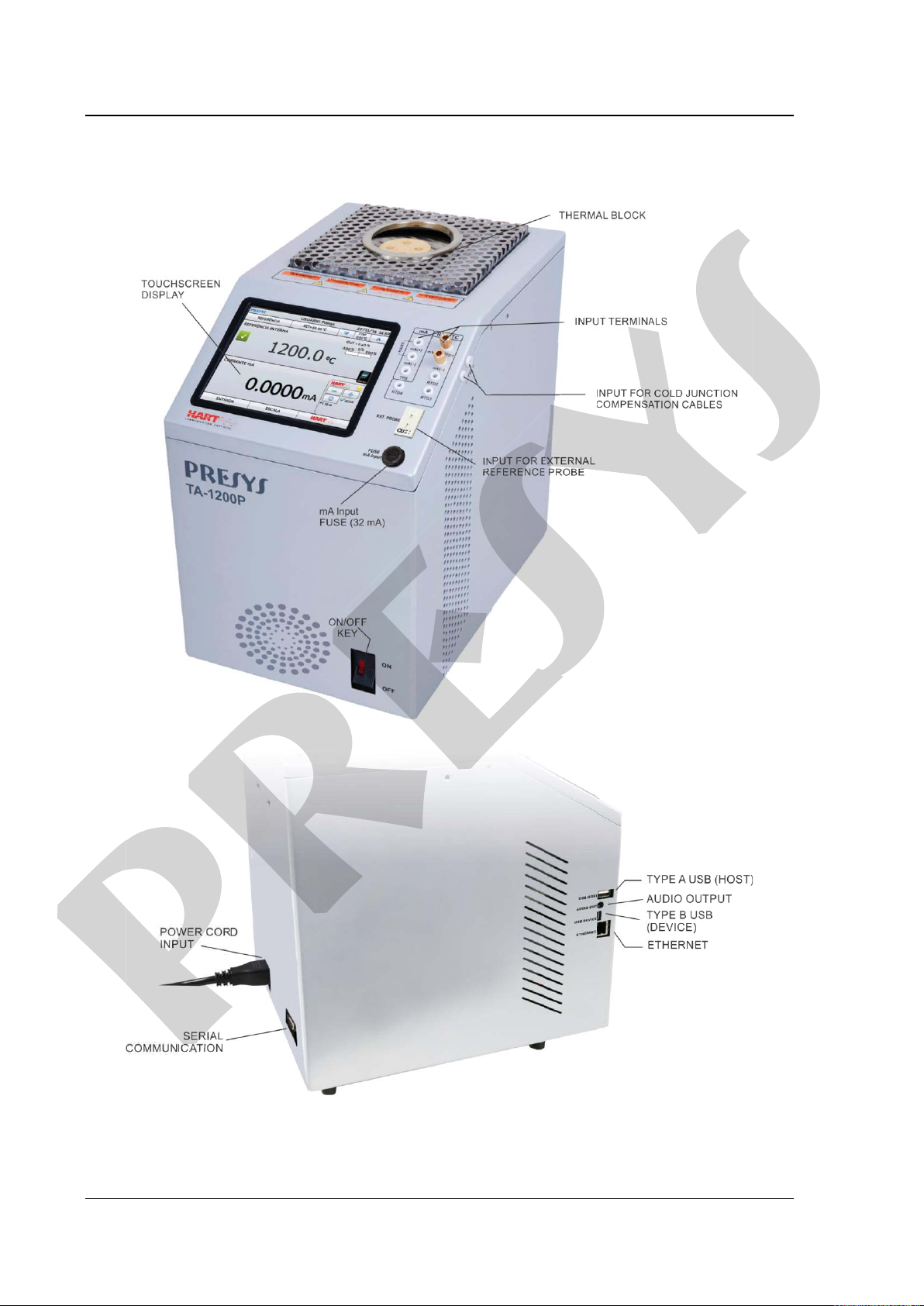
1.7 - Parts Identification
Fig. 05-Parts Identification
presys
presys
PRESYS Instruments TA-1200P
Page 11
2 - Calibrator Operation
When powered on, the calibrator goes through a self-test routine and shows the
last adjustment date. In case of failure, it displays a message to indicate error; if that
occurs, the instrument should be sent to manufacturer for repair.
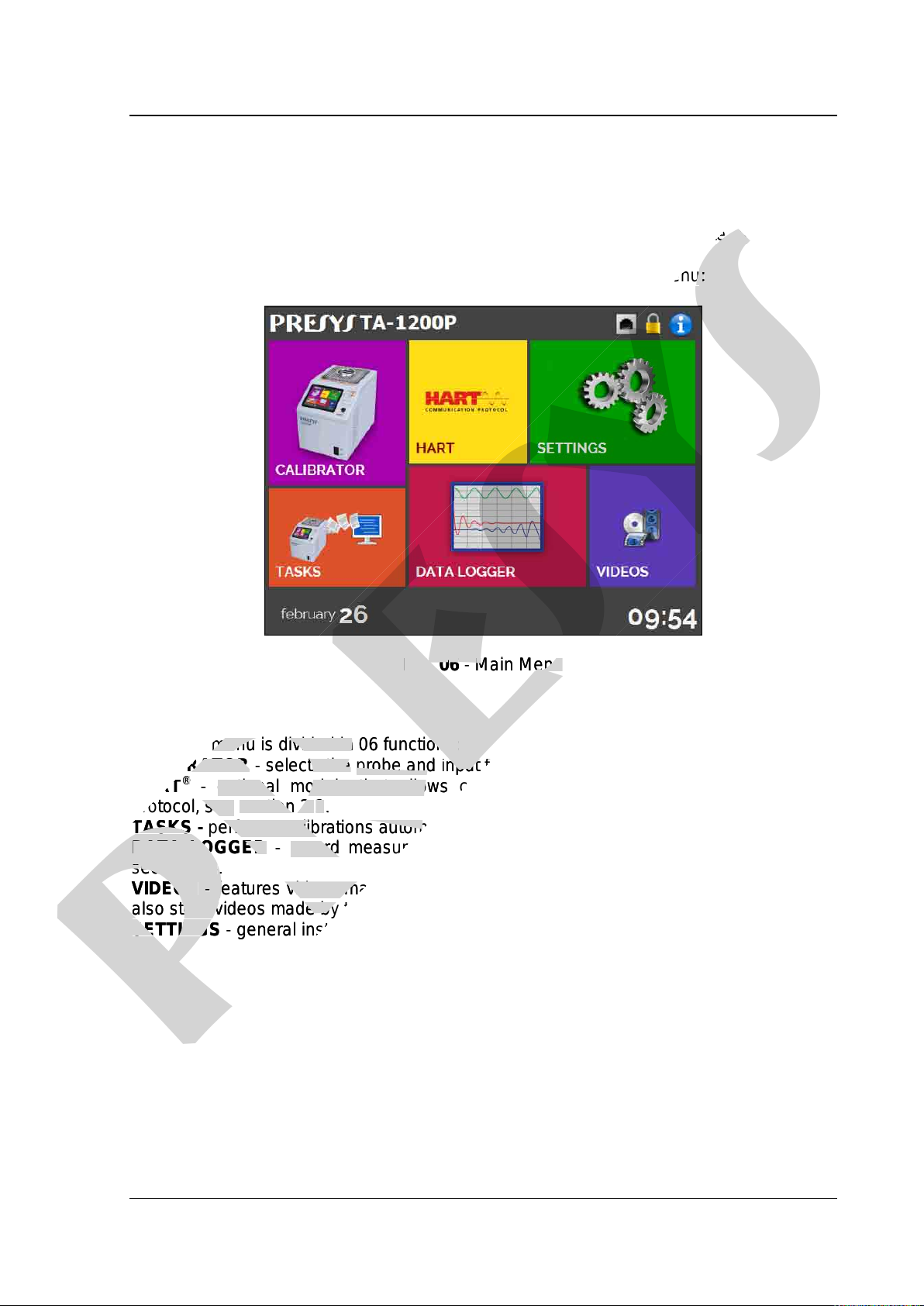
After the self-test is completed, the display shows the main menu:
Fig. 06-Main Menu
The main menu is divided in 06 functions:
CALIBRATOR -selects the probe and input functions, see section 2.1
HART®-optional module that allows communication with devices that have Hart®
protocol, see section 2.2.
TASKS -performs calibrations automatically, see section 2.3.
DATA LOGGER -record measurements, enabling visualization in chart or table, see
section 2.4.
VIDEOS -features videos made by Presys to assist in the use of the calibrator, and can
also store videos made by the user, see section 2.5.
SETTINGS -general instrument settings, see section 2.6.
presys
last adjustment date. In case of failure, it displays a message to indicate error; if that
presys
last adjustment date. In case of failure, it displays a message to indicate error; if that
test is completed, the display shows the main menu
presys
test is completed, the display shows the main menu
:
presys
:
presys
Fig. 0
presys
Fig. 0
6
presys
6
-
presys
-
Main Menu
presys
Main Menu
The main menu is divided in 06 functions:
presys
The main menu is divided in 06 functions:
CALIBRATOR
presys
CALIBRATOR
-
presys
-
selects the
presys
selects the
probe and
presys
probe and
input functions, see
presys
input functions, see
HART
presys
HART
®
presys
®
-
presys
-
optional module that allows communication with devices that have Hart
presys
optional module that allows communication with devices that have Hart
protocol, see
presys
protocol, see
section 2.
presys
section 2.
2
presys
2
.
presys
.
TASKS
presys
TASKS
-
presys
-
performs calibrations automatically, see
presys
performs calibrations automatically, see
DATA LOGGER
presys
DATA LOGGER
-
presys
-
record measurements, enabling visualization in chart or table, see
presys
record measurements, enabling visualization in chart or table, see
s
presys
s
ection 2.
presys
ection 2.
4
presys
4
.
presys
.
VIDEOS
presys
VIDEOS
-
presys
-
features videos made by Presys to assist in the use of the calibrator, and can
presys
features videos made by Presys to assist in the use of the calibrator, and can
also store videos made by the user, see
presys
also store videos made by the user, see
SETTINGS
presys
SETTINGS
-
presys
-
general instrument settings, see
presys
general instrument settings, see

PRESYS Instruments TA-1200P
Page 12
2.1 -Calibrator Menu
To select the probe set point or electrical input functions, from the main menu,
press the CALIBRATOR button. The following screen is displayed.
Fig. 07-Calibrator Function
At the top is shown the probe settings and values.
The centered value shows the block temperature. The GREEN color indicates that
the temperature is stable, otherwise it is RED.
The set point value appears on the top. Touch in the SET bar to change it.
Pressing on the temperature unit it can be changed between °C (Celsius), °F
(Fahrenheit) or K (Kelvin).
Fig. 08-Calibrator Mode
presys
presys
Calibrator Function
presys
Calibrator Function
probe settings and values.
presys
probe settings and values.
The centered value shows the block temperature.
presys
The centered value shows the block temperature.
The
presys
The
GREEN
presys
GREEN
color indicates that
presys
color indicates that
the temperature is stable, otherwise it is
presys
the temperature is stable, otherwise it is
RED
presys
RED
.
presys
.
The set point value appears on the top. Touch in the
presys
The set point value appears on the top. Touch in the
presys
SET
presys
SET
Pressing on the temperature unit it can be changed between °C (Celsius), °F
presys
Pressing on the temperature unit it can be changed between °C (Celsius), °F
K (Kelvi
presys
K (Kelvi
n).
presys
n).
presys
PRESYS Instruments TA-1200P
Page 13
In the STEP function, a step value can be configured, and the steps can be
changed through the up and down arrows.
In REFERENCE menu, you can configure the type of probe reference (see
section 2.1.1 –Probe Reference). The chosen reference appears just below the
REFERENCE button.
At the bottom, an input can be configured.When the input is selected, the screen
will split automatically. To select an input, just touch the INPUT bar (see section 2.1.2 -
INPUT MENU).
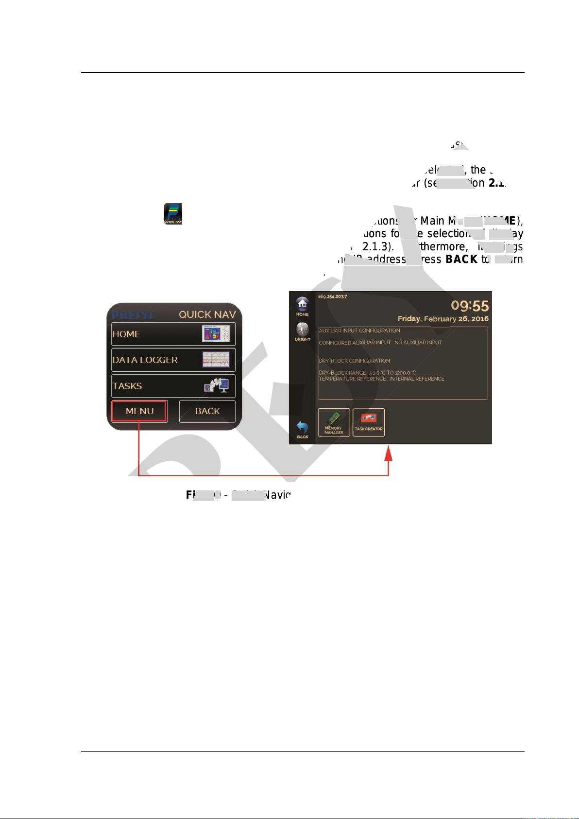
The icon shows a Quick Navigator, with the options for Main Menu (HOME),
Data-Logger and Tasks.Pressing MENU,there are options for the selection of display
Brightness and Memory Manager (see section 2.1.3). Furthermore, it brings
information about the auxiliary input configuration and IP address. Press BACK to return
to Calibrator Mode or HOME to go to Main Menu.
Fig. 09-Quick Navigator and Secondary Menu
presys
e chosen reference appears just below the
presys
e chosen reference appears just below the
When the input is selected, the screen
presys
When the input is selected, the screen
bar (see section
presys
bar (see section
2.1.2
presys
2.1.2
he options for Main M
presys
he options for Main M
e
presys
e
nu (
presys
nu (
HOME
presys
HOME
)
presys
)
,
presys
,
there are options for the selection of
presys
there are options for the selection of
display
presys
display
(see section 2.1.
presys
(see section 2.1.
3
presys
3
presys
). Furthermore, it bri
presys
). Furthermore, it bri
ngs
presys
ngs
y input configuration and IP address. Press
presys
y input configuration and IP address. Press
BACK
presys
BACK
to
presys
to
return
presys
return
to go to Main Menu.
presys
to go to Main Menu.
presys
Fig. 0
presys
Fig. 0
9
presys
9
-
presys
-
Quick Navigator and Secondary Menu
presys
Quick Navigator and Secondary Menu

PRESYS Instruments TA-1200P
Page 14
2.1.1 –Probe Reference
There are two different references to the thermal block:Internal Reference and
External Reference.
The Internal Reference is a sensor built into the block.
The External Reference is an option for more accurate measurements. The
reference comes from a Standard Thermocouple Sensor placed inside the insert, among
the DUT (devices under test). This Standard Sensor should be a noble metal
thermocouple (R, S or B type). To increase accuracy to the measurements, ITS-90
parameters can be used to correct the thermocouple electromotive force in reference to
the IEC-60751 table.
When used External reference, the probe indication is displayed on the screen
and the control is made by the internal probe.
Fig. 10 -Choosing the Type of Temperature Reference
To select the Reference between Internal and External, touch the REFERENCE
bar. Select a reference between the registered sensors. To add a new sensor select
MANAGER and ADD. When selecting External Reference, the ITS-90 parameters must
be set. If the sensor does not have parameters, use the value “zero” for all the
coefficients.
ID: Sensor Identification
TYPE: Thermocouple type (R, S, B)
Scale: Reference table for the thermocouple
MIN and MAX: Operating range for the thermocouple
CJC: Type of Cold Junction Compensation. If MANUAL is chosen, inform the
temperature.
C0,C1,C2 and C3: Thermocouple coefficients.
The coefficient values can be found in the Reference Sensor Certificate.
presys
is an option for more accurate measurements. The
presys
is an option for more accurate measurements. The
Sensor placed inside the insert, among
presys
Sensor placed inside the insert, among
should be a
presys
should be a
noble metal
presys
noble metal
(R, S or B type). To increase accuracy to the measurements,
presys
(R, S or B type). To increase accuracy to the measurements,
ITS
presys
ITS
-
presys
-
90
presys
90
can be used to correct the thermocouple electromotive force in reference to
presys
can be used to correct the thermocouple electromotive force in reference to
the probe indication is displayed on the screen
presys
the probe indication is displayed on the screen
presys
Fig.
presys
Fig.
10
presys
10
-
presys
-
Choosing the Type of Temperature Reference
presys
Choosing the Type of Temperature Reference
To select the Reference between Internal and External, touch the
presys
To select the Reference between Internal and External, touch the
bar.
presys
bar.
Sel
presys
Sel
ect a reference between the registered sensors. To add a new sensor select
presys
ect a reference between the registered sensors. To add a new sensor select
MANAGER
presys
MANAGER
and
presys
and
ADD.
presys
ADD.
When selecting External Reference, the ITS
presys
When selecting External Reference, the ITS
be set. If the sensor does not have parameters, use the value “zero” for all the
presys
be set. If the sensor does not have parameters, use the value “zero” for all the
coefficients.
presys
coefficients.
ID:
presys
ID:
S
presys
S
ensor Identification
presys
ensor Identification
TYPE:
presys
TYPE:
Thermocouple type (R, S, B)
presys
Thermocouple type (R, S, B)
Scale:
presys
Scale:
Reference table for the thermocouple
presys
Reference table for the thermocouple
MIN
presys
MIN
and
presys
and
MAX
presys
MAX
CJC
presys
CJC
: Type of Cold Junction Compensation. If MANUAL is chosen, inform the
presys
: Type of Cold Junction Compensation. If MANUAL is chosen, inform the
temperature.
presys
temperature.

PRESYS Instruments TA-1200P
Page 15
Fig. 11 -Adding a new Reference Sensor
After filling the blanks, click on SAVE button and confirm. The new sensor is now
available to be chosen in the list. To edit data from a sensor, select it and press
MANAGER button. To remove a sensor, select it and press REMOVE
Fig. 12-Connecting the Standard Sensor for the External Reference
Note: the values corresponding to controlled temperatures appear in GREEN /RED.
Values that show only the sensor indication appear in BLACK.
presys
presys
Adding a new Reference Sensor
presys
Adding a new Reference Sensor
SAVE
presys
SAVE
button and confirm. The new sensor is now
presys
button and confirm. The new sensor is now
the list. To edit data from a sensor, select it and press
presys
the list. To edit data from a sensor, select it and press
button. To remove a sensor, select it and press
presys
button. To remove a sensor, select it and press
presys
REMOVE
presys
REMOVE
presys
Table of contents
Other Presys Test Equipment manuals

Presys
Presys MCS-XV User manual

Presys
Presys T-1200PH User manual

Presys
Presys TA-1200PLAB User manual

Presys
Presys T-350P User manual

Presys
Presys PCON-Y18-LP User manual

Presys
Presys T-500PIR User manual

Presys
Presys PCA-570-RM User manual

Presys
Presys MCS-12-IS User manual

Presys
Presys T-1200PIR User manual

Presys
Presys PC-507-IS User manual

Popular Test Equipment manuals by other brands


Tektronix
Tektronix MDO4104 Technical reference

Oakton
Oakton Eutech Instruments TDSTestr11+ instruction manual

Martindale Electric
Martindale Electric HPAT600/2 HANDYPAT instruction manual

SIGLENT
SIGLENT SDS1000X-E Series Service manual

Kewtech
Kewtech KEWPROVE 4 manual

Hioki
Hioki MEMORY HiCORDER 8855 instruction manual


