Presys T-1200PH User manual
EM0354-00
Technical Manual
R
Dry Block Calibrator
T-1200PH


WARNING!
Avoid electric shock risk when touching the equipment:
- Use only suitable power cable with earth connection;
- Never power the equipment to the mains socket with no earth connection.
WARNING!
High voltage is present inside this equipment.
It can cause great damages and injuries.
Do not make any repair service inside the equipment without removing
the plug from the supply.
WARNING!
Much electromagnetic noise can cause instability to the equipment.
The equipment is provided with electromagnetic interference filters that protect
not only the mains but also the equipment itself against noise. These filters have no
function if the unit is not earthed properly.
WARNING!
High temperatures are achieved in this equipment.
Risk of fire and explosion are present in case safety measures are not taken.
Sign by means of warnings the hazardous areas at high temperatures.
Do not place the dry-block on inflammable surfaces or even on materials that
can be deformed due to high temperatures.
Do not obstruct any air-vent to avoid risk of fire in the equipment.
CAUTION!
The instrument described in this technical manual is intended to be used in a
specialized technical area. The user should be responsible by its configuration and the
parameter values entered. Factory warns about risks of personal injury or ambient
damage as a result of its incorrect use.
CAUTION!
Do not raise the setpoint in steps higher than 500 °C in order to increase
heater lifetime.

CAUTION!
Before first use, after transportation and whenever the dry block is not used
within a 10-day period, the instrument should be heated to 600 °C for 1 or 2 hours.
CAUTION!
This equipment contains ceramic fiber components. Persons in direct contact
with surch materials should take preventive measures when handling them.
WARNING!
Never remove the insert from the dry-block or the thermo-elements from the
insert, while they are in temperatures far from the ambient. Wait until they reach the
ambient temperature so that the heterogeneous cooling of the parts do not jam each
other.

PRESYS Instruments T-1200PH
EM0354-00
Table of Contents
1 - Introduction ...............................................................................................................1
1.1 - Technical Specifications........................................................................................2
1.1.1 - Input Technical Specifications........................................................................3
1.2 - Initial Usage..........................................................................................................3
1.3 - Mounting the insert inside the furnace ..................................................................3
1.4 - Instruction for use of the optional Black Body insert..............................................4
1.5 - Order Code...........................................................................................................5
1.6 - Accessories ..........................................................................................................6
2 - T-1200PH Calibrators Operation ..............................................................................7
2.1 - Menu IN................................................................................................................8
2.1.1 - Input Connections Diagrams ..........................................................................9
2.2 - Menu CONF........................................................................................................10
2.3 - Manual Operating Mode......................................................................................13
2.4 - Programmable Operating Mode..........................................................................13
2.5 - Automatic Operating Mode .................................................................................14
3 - Recommendations as regards Accuracy of Measurements ................................16
3.1 - Getting a Better Accuracy from the Dry Block.....................................................16
4 - Safety Instructions..................................................................................................17
5 - Calibrator Warning Messages ................................................................................17
6 - PID Control Parameters ..........................................................................................18
7 - Calibration................................................................................................................19
7.1 - Input Calibration..................................................................................................19
7.2 - Probe Calibration................................................................................................20
8 - Maintenance.............................................................................................................22
8.1 - Instructions for Hardware....................................................................................22
9 - Instructions for Fitting the Strap for Transport ....................................................22


PRESYS Instruments T-1200PH
Page 1
1 - Introduction
T-1200PH
T-1200PH dry block calibrators control temperature of an insert in order to
calibrate thermocouples, thermoresistances, glass thermometers, thermoswitches etc.
Besides providing high accuracy temperature values, they also allow the measurement of
signals generated by thermo-elements like thermocouples, thermoresistances and
thermoswitches, which are being calibrated. This is possible due to an embedded
calibrator specific for these types of signal, including 4-20 mA. Thus, they incorporate the
functions of dry block, standard thermometer and calibrator for RTD, TC and also mA.
T-1200PH calibrators model generate temperatures from 50 ºC (122 ºF) to 1200
ºC (2192ºF).
Present input for thermocouples, thermoresistances, thermoswitches. Besides
generating temperature, they measure the signal from the sensor being
calibrated.
Carry out completely automatic calibrations with or without the use of a computer.
Accuracy to 3 ºC of reading, stability of 0.2 ºC and resolution of 0.1 ºC.
Documenting capabilities: communication with computer and ISOPLAN
Calibration Software.
Portable, compact and, provide interchangeable inserts.
They present a wide variety of programming resources, allowing the performance
of automatic calibrations of thermocouples, thermoresistances, thermoswitches. In this
case, the sensor is placed in the insert and their electrical terminals are connected to the
embedded calibrator. The operator defines the calibration points and the number of
repetitions, then the process is started and all the sequence is automatically
accomplished.

PRESYS Instruments T-1200PH
Page 2
Another way of performing automatic documented calibrations is by means of
ISOPLAN Calibration Software for PC/WindowsTM, which uses RS-232 or RS-485 serial
communication to connect the computer to the dry block. With ISOPLAN it is possible to
register sensors and instruments of a factory, generate work orders, create and print
calibrations certificates and reports, that is, it brings all advantages of computer data
management to the calibration environment.
T-1200PH have also many other features, such as:
The electric signal calibrator is independent from the dry block function.
Internal buzzer beeps when the temperature reaches the desired value.
Keypad that eases the operation and configuration of the calibrator.
Graphic liquid crystal display to present big-size digit numbers.
Thermo-element reading scaled to ITS-90 or IPTS-68.
Internal regulated 24 vdc power supply for 2-wire transmitters.
Internal rechargeable battery and battery charger included in the electric signal
calibrator.
Independent circuitry for overtemperature protection and safety.
Insert to choose, carrying case, strap and test leads included. If the insert is not
specified, it will be provided the insert type BP06.
1.1 - Technical Specifications
T-1200PH
Operating Range
50 ºC (122 °F) to 1200 °C (2192 °F)
Power Supply
110 Vac or 220 Vac 50/60Hz, according to order code.
Resolution
0.1 ºC or 0.1 ºF
Accuracy
3.0 °C
Stability
0.2 ºC
Power Consumption
2300 W
Heating Rate
45 minutes (100 ºC to 1200 ºC)
Cooling Rate
5 h (1200 ºC to 200 ºC)
Calibration Volume
34 mm / 130 mm depth
Standard Insert coming with
the furnace
2 holes of 6 mm and 2 holes
of ¼” x 80 mm depth
Homogeneity
0.2 °C
Dimensions (H,W,D)
215 x 390 x 310mm
Weight
10,3 kg
Warranty
1 year

PRESYS Instruments T-1200PH
Page 3
1.1.1 - Input Technical Specifications
Input Ranges
Resolution
Accuracy
Remarks
millivolt -150 to 150 mV
-500 to -150 mV
150 to 2450 mV
0.001 mV
0.01 mV
0.01 mV
± 0.01 % FS
± 0.02 % FS
± 0.02 % FS
R input > 10 M
auto-ranging
mA -5 to 24.5 mA
0.0001 mA
± 0.02 % FS
R input < 160
Resistance 0 to 2500
0.01
± 0.008 % FS
excitation current
0.9 mA
Pt-100 -200 to 850 ºC / -328 to 1562 ºF
0.01 ºC / 0.01 ºF
± 0.1 ºC / ± 0.2 ºF
IEC-751
Pt-1000 -200 to 400 ºC / -328 to 752 ºF
0.1 ºC / 0.1 ºF
± 0.1 ºC / ± 0.2 ºF
IEC-751
TC-B 50 to 250 ºC / 122 to 482 ºF
250 to 500 ºC / 482 to 932 ºF
500 to 1200 ºC / 932 to 2192 ºF
1200 to 1820 ºC / 2192 to 3308 ºF
0.1 ºC / 0.1 ºF
0.1 ºC / 0.1 ºF
0.1 ºC / 0.1 ºF
0.1 ºC / 0.1 ºF
± 2.5 ºC / ± 5.0 ºF
± 1.5 ºC / ± 3.0 ºF
± 1.0 ºC / ± 2.0 ºF
± 0.7 ºC / ± 1.4 ºF
IEC-584
IEC-584
IEC-584
IEC-584
TC-J -210 to 1200 ºC / -346 to 2192 ºF
0.1 ºC / 0.1 ºF
± 0.2 ºC / ± 0.4 ºF
IEC-584
TC-K -270 to -150 ºC / -454 to -238 ºF
-150 to 1370 ºC / -238 to 2498 ºF
0.1 ºC / 0.1 ºF
0.1 ºC / 0.1 ºF
± 0.5 ºC / ± 1.0 ºF
± 0.2 ºC / ± 0.4 ºF
IEC-584
IEC-584
TC-N -260 to -200 ºC / -436 to -328 ºF
-200 to -20 ºC / -328 to -4 ºF
-20 to 1300 ºC / -4 to 2372 ºF
0.1 ºC / 0.1 ºF
0.1 ºC / 0.1 ºF
0.1 ºC / 0.1 ºF
± 1.0 ºC / ± 2.0 ºF
± 0.4 ºC / ± 0.8 ºF
± 0.2 ºC / ± 0.4 ºF
IEC-584
IEC-584
IEC-584
TC-R -50 to 300 ºC / -58 to -572 ºF
300 to 1760 ºC / 572 to 3200 ºF
0.1 ºC / 0.1 ºF
0.1 ºC / 0.1 ºF
± 1.0 ºC / ± 2.0 ºF
± 0.7 ºC / ± 1.4 ºF
IEC-584
IEC-584
TC-S -50 to 300 ºC / -58 to -572 ºF
300 to 1760 ºC / 572 to 3200 ºF
0.1 ºC / 0.1 ºF
0.1 ºC / 0.1 ºF
1.0 ºC / 2.0 ºF
0.7 ºC / 1.4 ºF
IEC-584
IEC-584
1.2 - Initial Usage
Identify if the following parts are present:
Dry block T-1200PH;
Metallic insert;
Inferior insulator of the insert (only one central hole);
Superior insulator of the insert (usually more than one hole);
Power cable;
Technical Manual.
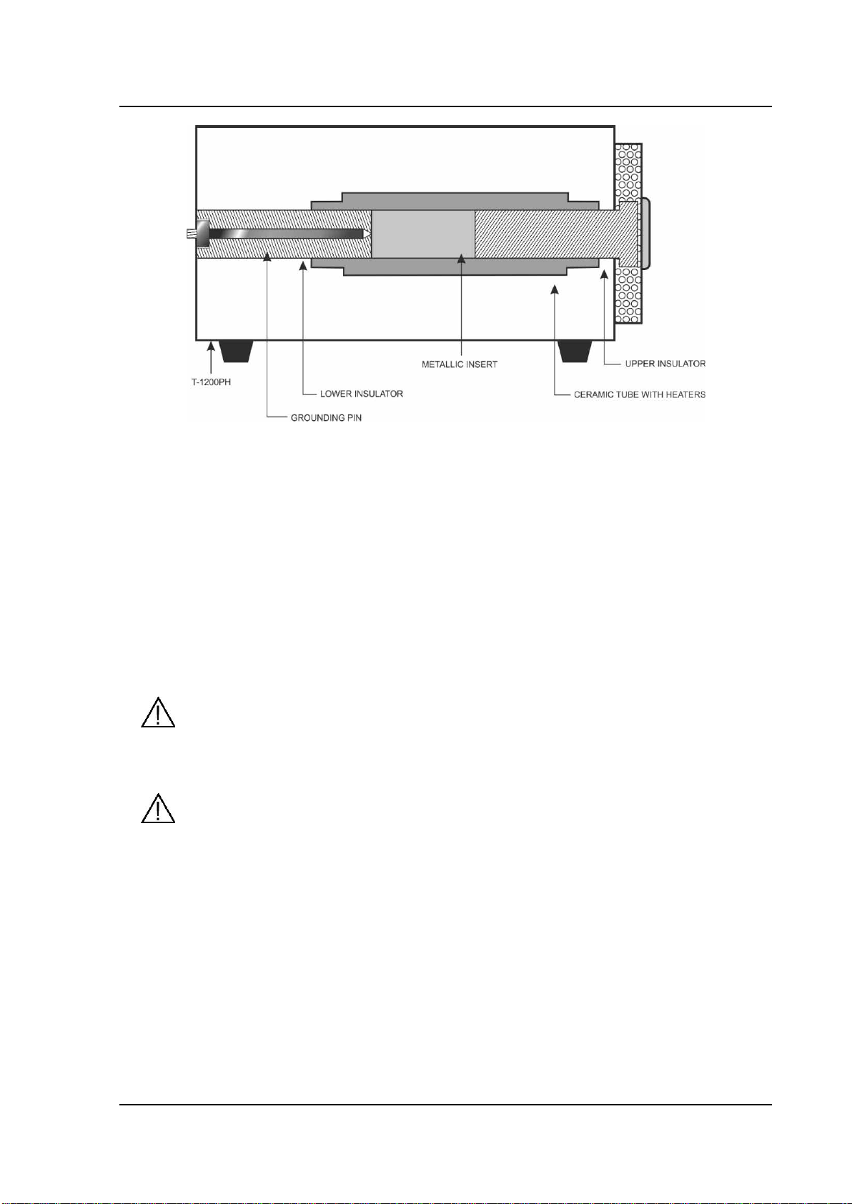
1.3 - Mounting the insert inside the furnace
The core of the T-1200PH consists of a ceramic tube. Thus, for safety reasons,
the insert and isolators are separate. To mount the assembly, you must first slide the
rear insulator smoothly through the ceramic tube. Then, with the metal insert secured by
the insert puller, slide it through the ceramic tube. After the metal insert, place and finish
the front insulator closing the lid and screwing it, preventing the front insulator from
falling. The sensor to be tested can then be inserted, observing that it must pass through
the front isolator and deepen inside the metal insert to obtain a correct temperature
measurement.
PRESYS Instruments T-1200PH
Page 4
SCHEMATIC VIEW FOR INSERT MOUNTING
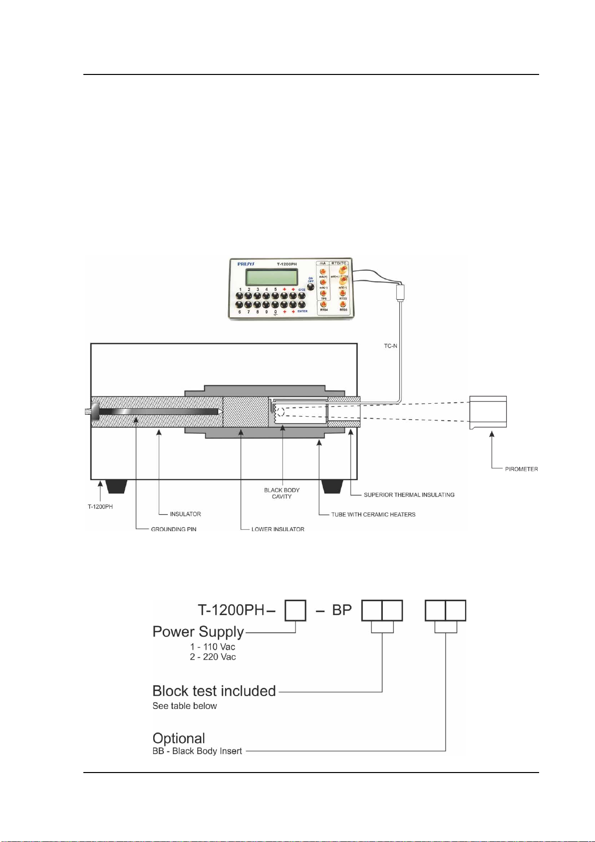
1.4 - Instruction for use of the optional Black Body insert
Insert of the Black Body
Identify the following parts and proceed to the mounting as explained:
Cylindrical Thermal insulator –Mounted in the lower part of the pit of the
furnace.
Metallic Insert type Black Body cavity –Must be introduced in the pit joined with
a thermocouple type N mounted laterally.
Careful when entering the thermocouple in the cavity to not force the fragile
ceramic wall pit.
Ring-shaped cylindrical Insulator - mounted on top of the pit of the furnace
Note that the position of the slit of insulation should match the type N
thermocouple sheath laterally.
Connect the terminals of the thermocouple type N to the auxiliary input side of
the furnace T-1200PH and set the reading of the IN input to N type
thermocouple.
The combination constitutes an excellent mounted cavity blackbody with
emissivity above 0,95 and an effective target of Ø 20 mm well suited for calibration of
optical pyrometers.
Align the pyrometer to be calibrated with a black body cavity in the furnace in a
vertical position.
PRESYS Instruments T-1200PH
Page 5
Observe the distance of the pyrometer to be calibrated against the background
of the black body cavity and the size of the actual target (Ø 20 mm) as specified in the
technical manual optical pyrometer.
Remember that the area targeted by the pyrometer to be calibrated must be
less than or equal to the effective target spot size of the blackbody in order to not
introduce measurement errors.
Use the certificate of calibration of the thermocouple type N to correct the
readings from the IN input of the calibrator and comparing the reading of the optical
pyrometer.
SCHEMATIC VIEW FOR MOUNTING OF THE BLACK BODY CAVITY
1.5 - Order Code

PRESYS Instruments T-1200PH
Page 6
1.6 - Accessories
Insert:
Inserts
Holes (insert external diameter: 1”)
Order Code
BP01
1 x 3/4"
06.04.0031-00
BP02
1 x 1/2"
06.04.0032-00
BP03
1 x 6.0 mm and 3 x 1/4"
06.04.0033-00
BP04
3 x 6.0 mm and 1 x 1/4"
06.04.0034-00
BP05
4 x 6.0 mm
06.04.0035-00
BP06
2 x 6.0 mm and 2 x 1/4"
06.04.0036-00
BP07
1 x 6.0 mm, 1 x 8.0 mm and 1 x 3/8"
06.04.0037-00
BP08
1 x 6.0 mm, 1 x 3.0 mm and 2 x 1/4"
06.04.0038-00
BP09
without hole, to be drilled by the client.
06.04.0039-00
BP10
Others, under ordering.
06.04.0040-00
* depth = 80 mm
Note: When asked, the calibration certificate will be provided for the first insert ordered.
Black Body Insert
Order code : BB-06.04.0074-00 Black Body
Special geometry pen type Insert and effective target 20 mm made of refractory
material. Constitutes a high emissive blackbody cavity for calibration of optical
pyrometers.
Communication Interface:
Description
Order Code
RS-232 - 9 way D type Connector (COM1)
06.02.0002-00
RS-232 - 25 way D type Connector (COM2)
06.02.0004-00
RS-485
06.02.0006-00
Carrying Case. Order Code: 06.01.0006-00.
ISOPLAN Software.
Calibration Certificate.

PRESYS Instruments T-1200PH
Page 7
2 - T-1200PH Calibrators Operation
The T-1200PH calibrators keep the block temperature controlled and allow the
reading of a thermo-element connected to its terminals. It is possible to verify the
thermocouple, thermoresistances, temperature transmitters etc together with the block
temperature value and temperature setpoint.
The calibrators have 3 operating modes:
Manual Mode to select the block temperature straight from the keypad.
Programmable Mode: 6 different programs with 11 temperature setpoint values. The
block temperature is selected among the programmed values by the keys and .
The Programmable Mode with Timer scans automatically the temperature setpoints.
Automatic Mode to calibrate thermo-elements. The thermo-elements calibration is
performed in an automatic way by the calibrator: the schedule and the calibration
results, besides the thermo-element readings are stored in the calibrator memory.
When powered on (ON/OFF key), the calibrator goes through a self-test routine
and shows the last calibration date and the value of the battery voltage. The battery
voltage is constantly monitored and the low battery warning is provided. After the self-test
is completed, the display shows the starting menu.
IN EXEC
CONF CAL COM
The initial setpoint is 50.00 ºC:
By means of keys ,,and , choose the menu options and press ENTER.
IN: selection of the calibrator signal input. Choose among mV, Ohms,
thermocouples, thermoresistances, mA, switch or none. More details in item 2.1 - Menu
IN. EXEC: The calibrator enters the manual or programmable operating mode.
CONF: Accesses the calibrator configuration options. More details in item 2.2 -
Menu CONF.
CAL: This option accesses the T-1200PH calibrator adjust functions, protected by
password. More details in section 7 - Calibration.
COM: Accesses the automatic calibration parameters. It is possible to perform a
calibration without a computer or using it (via CS-504 software). More details in item 2.5 -
Automatic Operating Mode.

PRESYS Instruments T-1200PH
Page 8
2.1 - Menu IN
mV OHM TC
RTD mA SW NO
mV, mA, SW: selects millivolt, milliampere or switch input, respectively.
OHM: selects ohms input. Following, choose from the menu the wiring in 2, 3 or 4-
wire.
2-WIRE 3-WIRE
4-WIRE
TC: selects thermocouple input. Choose among the B, J, K, N, Rand Stypes. In
the next menu, the internal or manual cold junction compensation is chosen.
INTERNAL
MANUAL
If the internal compensation is selected, the cold junction temperature value is
displayed by the calibrator. If the MANUAL option is selected, the cold junction must be
supplied by the operator. After confirming the value, by pressing ENTER, the calibrator
goes back to the operating mode.
RTD: Selects the type of thermoresistance used. Choose from PT100, NI100,
CU10 and PT1000 types. Choose also if the wiring is 2, 3 or 4-wire.
NO: Disables reading of external signal.
Selecting one of the options above, the calibrator goes straight to the manual
operating mode, with no need to select the EXEC option.
PRESYS Instruments T-1200PH
Page 9
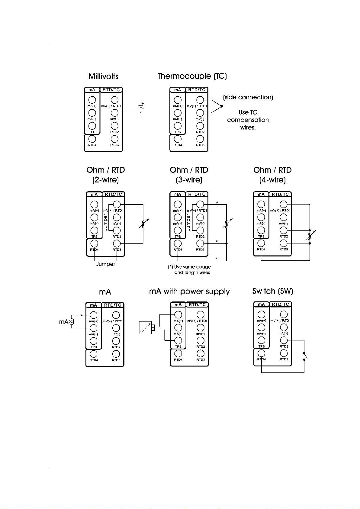
2.1.1 - Input Connections Diagrams

PRESYS Instruments T-1200PH
Page 10
2.2 - Menu CONF
CF PRG MEM LCD
SC BT DT BZ TU
CF: Selects the temperature unit between ºC or ºF. The ITS-90 or IPTS-68
temperature scales are selected for both the thermo-element and for the internal block
reference readings purpose.
ºC-90 ºF-90
ºC-68 ºF-68
LCD: This option sets the graphic liquid crystal display contrast. Use the keys
and until you get a better contrast and finish the operation by pressing the key
ENTER.
BT: Shows the battery or the battery charger voltage value if the dry block is
turned off or on, respectively.
Battery level
Battery state
Display
4.0 to 7.0 V
normal
----------
< 4.0 V
low
LOW BATTERY
DT: Updates the date and time of the calibrator. Thus, when the calibrator
performs a calibration in the automatic mode via CS-504, all data are registered together
with date and time of occurrence. Every time the calibrator is powered off, the internal
clock does not continue to be updated. However, the CS-504 software can automatically
update the calibrator date and time with the computer internal clock. Otherwise, use keys
and to change the field that blinks and the keys and to go to another field.
The key ENTER confirms the last selection.
BZ: Menu that configures the piezoelectric buzzer.
NO YES ENDCAL
NO: Disables the buzzer.
YES: The buzzer beeps when the block reaches the setpoint and
stabilizes.
ENDCAL: The buzzer beeps only at the end of a calibration in the
automatic operating mode.

PRESYS Instruments T-1200PH
Page 11
TU: Menu that configures the PID control parameters for the heating side. More
details in section 6 - PID Control Parameters.
K I D FACT
K: Proportional gain
I: Integral gain
D: Derivative gain
FACT: Restore the control parameters to the factory values.
PRG: Menu that programs the calibrator.
DEC_IN DEC_PRB
SETPOINT
DEC_IN: Selects the number of decimals of the thermo-element reading.
The default value depends on the input signal.
DEFAULT
0 1 2 3 4
DEC_PRB: Selects the number of decimals of the block temperature and
the setpoint value. The default number is 2.
0 1 2
SETPOINT: Enables the calibrator Programmable Operating Mode, and
allows the configuration of programmed values. The selected program is
indicated by the selection arrow. Choose one of the 6temperature programs or
NO to disable this Programmable Mode.
Select any of the 6 programs and confirm with the key ENTER. Following, it is
shown the menu of temperature setpoint configuration.
10% 20% 25%
VARIABLE
Change the configuration to steps (STEPS) of 10%, 20%, 25%, VARIABLE or
press C/CE to maintain the configuration already stored in memory. The temperature
range of the program must be configured through the values in SETPOINT HIGH and
SETPOINT LOW in case of 10%, 20% or 25% fixed steps of the range. The option
VARIABLE allows the user to define from 2 to 11 values of temperature setpoint, not
necessarily in ascending order.

PRESYS Instruments T-1200PH
Page 12
To verify the step values of a program, select the VARIABLE option and confirm
the values shown in the display with the key ENTER. The 10%, 20% and 25% options
change the number of steps automatically and recalculate the values according to
SETPOINT HIGH and SETPOINT LOW.
SC: This function scales the input reading. The scaling is very useful in
temperature transmitter calibration, for instance, because it displays the current
temperature and the transmitter reading (mA) in the same unit. Thus, the error can be
verified directly in ºC or ºF. Select the option SC and press ENTER. If no input is
selected in IN, the calibrator will show the SELECT INPUT FIRST message. In this
case, go to menu IN and select the input signal type.
The function SC will show IN or NO. Confirm IN to configure the scaling or NO to
disable the SC function, with the key ENTER.
The scaling is performed via the INPUT HIGH and INPUT LOW parameters,
corresponding to the maximum and minimum values of the calibrator signal input, in the
engineering unit of this signal. Next, configure the SCALE DEC (0-4), SCALE HIGH and
SCALE LOW parameters according to the maximum and minimum values of the
transmitter scale and the desired number of decimals. The scaled value is shown on the
display with the #unit.
For example, temperature transmitter with 0 to 100 ºC input and 4 to 20 mA
output. The scaling with one decimal would be:
INPUT HIGH: 20.0000 mA
INPUT LOW: 4.0000 mA
SCALE DEC (0-4): 1
SCALE HIGH: 100.0 #
SCALE LOW: 0.0 #
MEM: The T-1200PH calibrators allow many special programs and functions that
can be of frequent use. In situations like this, it would be useful to store the current
configuration in memory in order to save time. Up to 8 configurations can be stored in
memory.
Selecting the option MEM, it is possible to store the current configuration
(WRITE), restore a previous stored configuration (RECALL) or erase the 8
configurations from memory (CLEAR ALL).
WRITE RECALL
CLEARALL
Selecting the option WRITE or RECALL will present a new menu with numbers 1
to 8, representing each one of the memory positions. Choose one of the positions and
press ENTER. The writing operation (WRITE) can be made in an already used memory
position. The calibrator asks for the overwriting confirmation with the message
OVERWRITE MEMORY?. The CLEAR ALL operation shows a confirming message
ARE YOU SURE?. In both cases, press ENTER to confirm the operation or C/CE to
cancel.

PRESYS Instruments T-1200PH
Page 13
2.3 - Manual Operating Mode
The display shows the selected temperature value of the block and also the
current block temperature or thermo-element temperature value.
There are 4 ways in which the information are shown, covering the calibrator
input value (IN), the block temperature (PROB) and the temperature setpoint (SET). The
key interchanges the display presentation way:
IN = 23.456 mV
PROB= 300.0 ºC
PROB= 300.1 ºC
SET = 300.0 ºC
23.456
IN = Voltage (mV)
300.1
SET = 300.0 ºC
The block temperature setpoint is selected directly by the keypad, even if the
message SET is not being displayed. The numeric keypad enables the SET selection in
any of the display presentation ways, to change the setpoint.
The setpoint value is increased by key and decreased by key . While the
keys are kept pressed, the setpoint continues to be increased or decreased.
The key does not have function in the manual operating mode of the T-
1200PH calibrators.
Intermally, the setpoint changes at a limited rate to make possible a safer and
more homogeneous heating of the internal ceramic tube. Besides, the PID parameters
and algorithm were adjusted to assure a minimal stabilization time and overshoot.
2.4 - Programmable Operating Mode
Pre-configured programs can be loaded from the calibrators memory, enabling
the programmable operating mode. The temperature programmed values of the block
are used directly, with no need to enter the setpoint.
The display shows STEPn beside the block temperature setpoint value in the
programmable mode. The number of the program is indicated by n. Using the keys
and , the programmed values of temperature setpoint are changed. The numeric
keypad continues available for manual selection of the block temperature in the same
way of the manual operating mode.
The automatic scan over the programmed temperatures is implemented by
defining the stabilization time of the thermo-element in the block.
The key enables the automatic scan over the points. When pressed, the
message STEPn gives place to 0s and the calibrator waits for the stabilization time

PRESYS Instruments T-1200PH
Page 14
configured from 1 to 9 minutes, by the keys 1 to 9. The automatic scan is disabled by
pressing key again.
A countdown of the stabilization time is only started when the block temperature
reaches the programmed temperature and stabilizes within a range of approximately
0.20 ºC. At this time the buzzer beeps, in case it is configured to YES.
2.5 - Automatic Operating Mode
The thermo-element calibration is performed in an automatic way by the T-
1200PH calibrators. The configuration, as well as the calibration verification is carried out
by the calibrator itself. Also it is possible to use the CS-504 software and its work orders,
like a CAC - Computer Aided Calibration.
The independent automatic calibration, without the use of CS-504, is planned in
the option TAGMAN from menu COM.
TAG EXEC VERIF
ADDRESS TAGMAN
Before you start programming, configure first the signal that will be read by the
calibrator in the menu IN. To calibrate glass thermometers, for example, there is no
electric signal to be read. In this case, option IN from the menu must be configured to
NO and the calibrator will ask to enter the value indicated by the thermometer, at the end
of the stabilization time of each calibration point.
The data for an automatic calibration concern:
TAG: the thermo-element tag identification.
SP: the block temperature reference values for the calibration (calibration points).
TOL: the maximum tolerance for the thermo-element operation.
STB: the stabilization time, in seconds, so that the thermo-element temperature
indicates correctly. This timer starts just after the block reaches and stabilizes at the
setpoint temperature.
STR: the calibration strategy of the programmed reference values. The available
strategies are: (UP), (DOWN), (UP - DOWN), (DOWN - UP),
(UP - DOWN - UP) and (DOWN - UP - DOWN).
RP: the strategy number of repetitions.
RGI: the thermo-element indication range.
RGO: the operating temperature range that corresponds to the indication range
above.
The automatic calibration begins when the option EXEC from menu COM is
selected. All the operations are automatically performed by the T-1200PH calibrators.
The keypad does not work until the end of the calibration.
At the end of the stabilization time, the calibrator stores the thermo-element
reading in memory and goes to the next point, in case some input signal has been
previously configured in the menu IN and connected to the calibrator terminals.
The CALIBRATION END message appears on the display at the end of the
automatic calibration. Press ENTER to confirm. The results can be verified in option
VERIF from menu COM.
Table of contents
Other Presys Test Equipment manuals

Presys
Presys T-25N User manual

Presys
Presys MCS-12-IS User manual

Presys
Presys TA-1200PLAB User manual

Presys
Presys PC-507-IS User manual

Presys
Presys TA-1200P User manual

Presys
Presys T-1200PIR User manual

Presys
Presys MCS-XV User manual

Presys
Presys T-350P User manual

Presys
Presys T-500PIR User manual

Presys
Presys PCA-570-RM User manual


