Presys PCA-570-RM User manual

PRESYS
Instruments Advanced Pressure Calibrator
PCA-570
TECHNICAL MANUAL
PCA-570-RM
EM0431-01
PCA-570-DT

IMPORTANT RECOMMENDATIONS:
•Whenever possible keep the PCA-570 in dry environment.
•The fuse protecting the current measuring circuit, code 01.02.0277-21, is a special component. So, only
replace it with another original one, in order not to impair the accuracy of the PCA-570.
•In case of failure, contact Presys Technical Assistance.
•Being without daily use, leave it on for one hour before starting the activities.
The conditions of guarantee can be found at available in our site:
www.presys.com.br/garantia

Table of contents
1 - INTRODUCTION......................................................................................................................................................1
1.1. General Description.............................................................................................................................................1
1.2. Specifications......................................................................................................................................................2
1.3. Special Software Features ..................................................................................................................................8
1.4. Order Code .........................................................................................................................................................9
2 - OPERATION ..........................................................................................................................................................10
2.1. Party identification.............................................................................................................................................10
2.2. Battery and charger (only for PCA-570 Portable)..............................................................................................14
2.3. Using the PCA-570: basics functions................................................................................................................16
2.4. Calibrator...........................................................................................................................................................17
2.4.1. Measurement or input functions..................................................................................................................19
2.4.2. Generation or output functions ...................................................................................................................28
2.4.3. Available Power Supplies...........................................................................................................................31
2.4.4. Special Input Functions ..............................................................................................................................32
2.4.5. Special Output Functions............................................................................................................................36
2.4.6. Save Actual Configuration (Memory Manager)...........................................................................................40
2.4.7. AD/Ratio.....................................................................................................................................................40
2.4.8. Bar Graph...................................................................................................................................................41
2.4.9. Calibration examples..................................................................................................................................41
2.5. HART®...............................................................................................................................................................44
2.5.1. HART®connections....................................................................................................................................45
2.5.2. Starting Communication .............................................................................................................................48
2.5.3. HART® Transmitter Measurement Range Adjustment (CH Option)...........................................................49
2.5.4. Adjusting the Measuring Range of the HART®Transmitter with Reference (Option CH) ...........................50

2.5.5. HART®Transmitter mA Output Adjustment................................................................................................53
2.5.6. Full-Hart Configurator (FH Option)..............................................................................................................54
2.6. Data Logger ......................................................................................................................................................59
2.7. Automated Tasks ..............................................................................................................................................61
2.7.1. Creating Tasks............................................................................................................................................62
2.7.2. Running tasks.............................................................................................................................................65
2.7.3. Visualizing results.......................................................................................................................................67
2.7.4. Advanced Task Options..............................................................................................................................69
2.8. Help Desk..........................................................................................................................................................70
3 - SETTINGS..............................................................................................................................................................71
3.1. Date and Time...................................................................................................................................................71
3.2. Network.............................................................................................................................................................71
3.3. Services ............................................................................................................................................................72
3.3.1 Remote Access - Web Server .....................................................................................................................73
3.3.2 Remote Access - VNC.................................................................................................................................75
3.3.3 SCPI Commands List ..................................................................................................................................75
3.4. System..............................................................................................................................................................78
4 - ADJUST..................................................................................................................................................................80
4.1. Input Adjustment ...............................................................................................................................................81
4.2. Output Adjustment.............................................................................................................................................81
4.3. Pressure Calibration..........................................................................................................................................84
5 - MAINTENANCE .....................................................................................................................................................85
5.1. Battery Replacement (only for PCA-570 portable)............................................................................................85
5.2. Power input fuse replacement...........................................................................................................................87
6 - PRESSURE UNITS CONVERSION.......................................................................................................................89

1
1 - INTRODUCTION
1.1. General Description
The Advanced Pressure Calibrator PCA-570 has levels of performance only comparable to laboratory
standards, having accuracy from to 0,025 % of full scale. It allows the measurement of several pressure ranges, as
well as the measurement and generation of volt and mA signals. It is designed to offer the necessary resources in
order to facilitate the work of keeping the process instruments adjusted and calibrated.
Its construction considers the use in the field, includes items of great value as: Bag with shoulder strap
allowing freedom for hands, 5.7" display with backlight led facilitating visibility in environments with little lighting,
rechargeable battery and large memory capacity to store the values obtained allowing their transfer to the
microcomputer when necessary. Besides these, several factors can be cited constructive which aggregate quality
and efficiency to PCA-570, including predict your utilization not only in field as also in rack (Version RM –Rack
Mounting, Version DT –Desktop).
Incorporates to most modern union concepts such as adjustments and calibrations with informatics, where
the data are shared by both the instrument and the computer, giving efficiency to the treatment of information, in the
form of emission of reports and certificates, of the automated management of tasks and of the organization and
archiving of data, that is, it covers a whole context directed to the fulfillment of quality procedures, mainly related to
the ISO-9000 standard. It also has HART®communication (optional) for reading and settings parameters of field
devices that have this protocol.
Can be providing with until four pressure sockets. So, in a single calibrator, can have different ranges of
pressure, for example: vacuum, 0 to 100 psi, 0 to 1000 psi and 0 to 3000 psi, or any other combination of the ranges
available. It can also be purchased with a certain number of sensors capsules and later be added others sensors.
For adding pressure sensors beyond of available in the calibrator, there is a possibility of acquisition of external
pressure module (MPYA) that communicates with the PCA-570 via USB port.
Other optional is the high accuracy sensor that, from its numerous functions, can function as default
thermometer. So, at the same time as indicates the reference temperature, possibility the calibration of any other
temperature sensor.
2
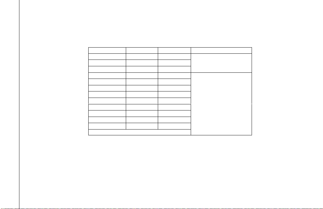
1.2. Specifications
Pressure capsule
Can be put until 4 pressure capsules in the PCA-570, with ranges varying of 25 mbar until 700 bar.
Ranges *
Resolution
Accuracy**
Observations
(0) 25 mbar
0,001
0,05 %
Gauge pressure.
Using with air or inert gases.
(1) 70 mbar
0,0001
0,05 %
(2) 350 mbar
0,0001
0,025 %
(3) 1 bar
0,0001
0,025 %
Gauge or
absolute pressure.
Using with fluids (gases
or liquids)
compatible with 316 L
stainless steel.
(4) 2 bar
0,0001
0,025 %
(5) 7 bar
0,001
0,025 %
(6) 20 bar
0,001
0,025 %
(7) 35 bar
0,01
0,025 %
(8) 70 bar
0,01
0,025 %
(9) 210 bar
0,01
0,025 %
(10) 350 bar
0,1
0,025 %
(11) 700 bar
0,1
0,05 %
(12) Others on request.
(*) Absolute pressure (ranges 3 to 8), gauge, vacuum (only for range 3), composed (of range 3 to 8) or differential (of range 0 to 2).
(**) Percentage of full scale.
Note: The differential capsule occupied two pressure sockets.
Obs.: Optional BR (Barometric Reference –15 psia)
Sensor for measurement of barometric pressure. Can be used for simulate the indication of absolute pressure in the other
ranges. Accuracy of ± 0,02 % FS (15 psia).
The values of accuracy includes a period of one year and ambient temperature of 20 and 26 °C. Outside
this range, the thermal stability is the 0,005 % FS / °C, with reference to 23 °C. Such values are achieved through
compensation algorithms of temperature about pressure measurement.

3
Auxiliart Inputs and Outputs
Input Ranges
Resolution
Accuracy
Observations
Volt
-10 V to 11 V
11 V to 45 V
0,0001 V
0,0001 V
0,02 % FS*
0,02 % FS
Rinput > 1 M
mA
-5 mA to 24,5 mA
0,0001 mA
0,01 % FS
Rinput < 120
Probe Range**
Resolution
Accuracy***
Observations
Pt-100
-200 to 850 C / -328 to 1562 F
0,01 C / 0,01 F
0,1 C / 0,2 F
IEC 60751
Output Ranges
Resolution
Accuracy
Observations
volt
-0,5 V to 12 V
0,0001 V
0,02 % FS
Routput < 0,3
mA
0 to 24 mA
0,0001 mA
0,02 % FS
Rmaximum = 700
Transmissor
a dois fios
4 mA to 24 mA
(XTR)
0,0001 mA
0,02 % FS
Vmaximum = 60 V
(*) FS = Full scale.
(**) Probe is a independent input for reference thermoresistance, for use with default thermometer.
(***) The accuracy mentioned is relative only in the input of PCA-570.
The values of accuracy include a period of one year and ambient temperature between 20 and 26 °C.
Outside this range, the thermal stability is the 0,001 % FS / C, with reference to 23 C.

4
Optionals
Probe
The Probe is a Pt-100 to four wires of high accuracy, provided on request. The calibrator input accepts
Callendar-Van Dusen and ITS-90 curves correction coefficients.
Pressure Module MPYA
Independent module for pressure measurement, provided on request.
The MPYA communicates with PCA-570 which performs the pressure
indication. Consult the MPYA specifications on Presys website.

5
Generals Specifications
Four-wire thermoresistance measurement (probe). Table IEC 60751, Callendar-Van Dusen or ITS-90 configurable.
Regulated Power supply for transmitters (TPS): 24 Vcc, with protection for short-circuit (30 mA).
Contact input for pressure switch calibration.
Input/output isolation: 50 Vcc.
Warm-up time: 5 minutes.
Operating temperature: 0 a 50 C.
Humidity relative: 0 a 90 % UR.
Pneumatic connection: 1/4” NPTF (Obs.: 1/8” NPTF only for range 0 –10000 psi or higher).
Overpressure: up to twice the full scale of the capsule (for capsules up to 5000 psi).
Engineering Units: Temperature: °C, °F, K; Pressure: psi, bar, mbar, MPa, kPa, Pa, atm, at, mH2O, mH2O@4°C,
mmH2O, mmH2O@4°C, cmH2O, cmH2O@4°C, ftH2O, ftH2O@4°C, inH2O, inH2O@4°C, inH2O@60°F, torr, mmHg,
mmHg@0°C, cmHg, cmHg@0°C, inHg, inHg@0°C, inHg@60°F, gf/cm2, kgf/cm2, kgf/m2.
Integrated Web server. Ethernet Communication, USB port or WiFi (with use of optional adapter).
HART®communication protocol (optional)..
Calibration certificate (optional).
1 year warranty.
6
Field Service Version (PCA-570). Ideal for Field use.
Rechargeable batteries with duration up to 8 hours with 12 mA current output
and 50% screen brightness.
Included accessories: technical manual, leads test, USB x micro USB cable,
network cable, carrying case and battery charger.
Dimensions: 140 mm x 250 mm x 80 mm (HxWxD).
Weight: nominal 1.5 kg.
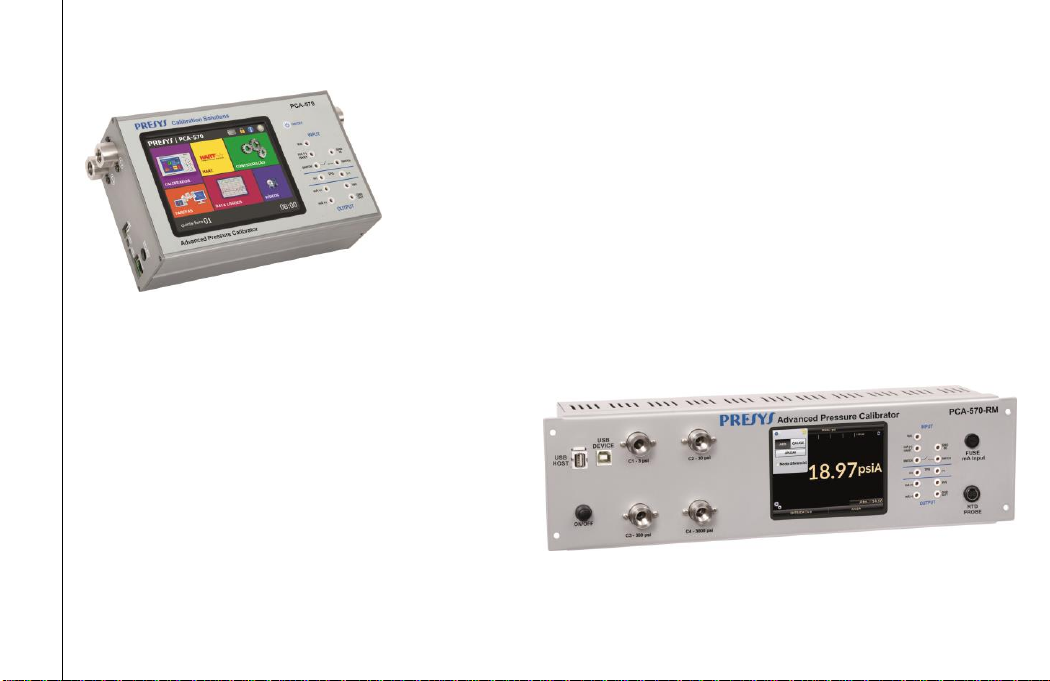
Rack Mounting Version (PCA-570-RM). Ideal for mounting on a bench or 19" rack.
Power supply from 100 to 240 Vac, 50 / 60 Hz.
Included accessories: technical manual, USB cable
(A/B), network cable and leads test.
Dimensions: 132 mm x 483 mm x 250 mm (HxWxD).
Weight: 4.0 kg nominal.

7
Desktop Version (PCA-570-DT). Ideal for bench use.
Power supply from 100 to 240 Vac, 50 / 60 Hz.
Included accessories: technical manual, USB x micro USB cable, network cable, and test leads.
Dimensions: 132 mm x 308 mm x 275 mm (HxWxD).
Weight: 3,0 kg nominal.
Notes:
* PCA-570 and ISOPLAN are trademarks of Presys.
* Changes can be made to the instrument by changing the specifications described in this technical manual.
* HART®is a trademark of FieldComm Group.

8
1.3. Special Software Features
- Special functions:
1) SCALE: scale both input and output.
2) CONV: converts any input to any output, galvanically isolated.
3) RAMP: increasing or decreasing ramps with configurable run times and plateau.
4) STEP: steps or setpoints with configurable times.
- Memory manager: Storage of user-defined configuration types.
- Automated tasks: creation of calibration work orders and automatic execution of calibrations, storage of obtained
data, and emission of reports and certificates.
- Data Logger: monitoring the input or output signals, storing and displaying the data in graphs or tables.
- Help Desk: storing and viewing videos and documents on the calibrator itself.
9
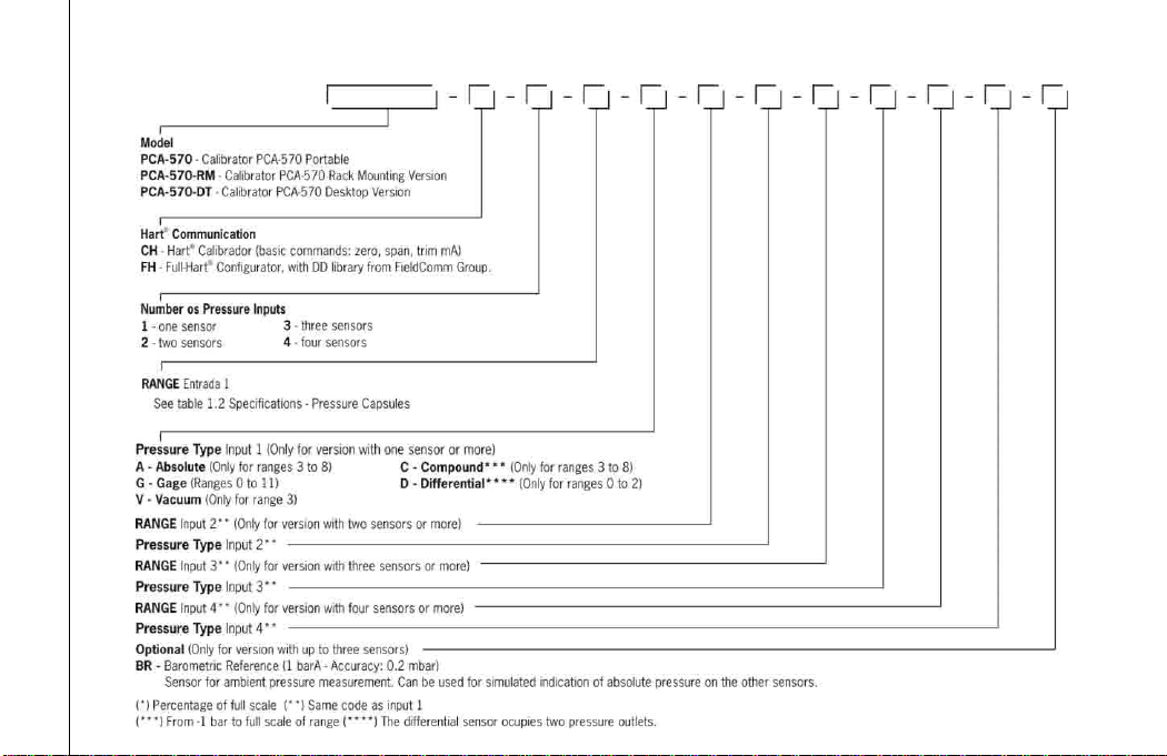
1.4. Order Code

10
2 - OPERATION
2.1. Party identification
PCA-570 Portable
Front Panel
Fig. 01 - Front Panel –PCA-570

11
Left side panel Right side panel
Fig. 02 - Side panels –PCA-570
Accessories: The carrying bag has three compartments, one to hold the calibrator and the others to hold various
accessories including test leads, spare fuse, handles for carrying and field use, and a technical manual.
Optional: are optional the pressure capsules, high accuracy temperature sensor (PROBE), the pressure module
(MPYA) beyond ISOPLAN software. The optional are describe in the specific manual.

12
PCA-570-RM (Rack Mounting Version)
Fig. 04 - Front and Back Panels –PCA-570-RM

13
PCA-570-DT (Desktop Version)
Fig. 05 - Front and Back Panels –PCA-570-DT

14
2.2. Battery and charger (only for PCA-570 Portable)
The PCA-570 is providing with battery rechargeable allowing up to 10 hours of continuous use. This
autonomy is reduced according to the active functions. A charger is include that can be connected to a voltage of 100
to 240 Vac. The time for a full charge is 3 hours.
The level of battery is indicated in main screen, as shown below.
Fig. 06 - Main Screen

15
Fig. 07 - Battery Levels
Clicking on the battery icon brings up the next screen. This screen shows the battery charge (in percent), the
current (positive value if the battery is being charged and negative otherwise), and the estimated runtime of the
instrument based on battery consumption.
Fig. 08 - Battery Status

16
The charger charges the battery at the same time as it powers the calibrator, allowing the calibrator to be
used normally while the battery is being charged.
The batteries used by the PCA-570 are Lithium Polymer (Li-Po). This rechargeable battery technology
doesn't have the undesirable memory effect characteristics of its Nickel Cadmium (Ni-Cd) predecessors.
To avoid explosion or fire, only use the battery charger supplied by Presys, don't short circuit and don't
damage the battery.
2.3. Using the PCA-570: basics functions
When turned on, the calibrator performs a self-test routine and shows the date of the last calibration. In case
of failure, an error message is displayed; restart the device and if the problem persists, call technical assistance.
After the self-test, the display starts showing the main screen as shown in the figure 06.
The main screen is divided into 6 functions:
CALIBRATOR –selects input / output functions, see section 2.4.
HART®–optional module, allows communication with devices that have HART® protocol, see section 2.5.
SETTINGS –general instrument settings, see section 3.
TASKS –executa calibrações automaticamente, ver seção 2.7.
DATA LOGGER –records measurements over time, making it possible to view them in graph or table, see section
2.6.
HELP DESK –has videos made by PRESYS to assist in the use of the calibrator and can also store videos and
documents made by the user, see section 2.9.
This manual suits for next models
1
Table of contents
Other Presys Test Equipment manuals

Presys
Presys T-1200PIR User manual

Presys
Presys TA-1200P User manual

Presys
Presys T-25N User manual

Presys
Presys PCON-Y18-LP User manual

Presys
Presys MCS-12-IS User manual

Presys
Presys TA-1200PLAB User manual

Presys
Presys PC-507-IS User manual

Presys
Presys T-350P User manual

Presys
Presys T-500PIR User manual

Presys
Presys T-1200PH User manual

Popular Test Equipment manuals by other brands


Midtronics
Midtronics Celltron ULTRA instruction manual

Aeroflex
Aeroflex IFR 4000 Initial verification

Reed Instruments
Reed Instruments TM-8811 instruction manual

Hioki
Hioki 7016 Remote Operation Manual

LaserLiner
LaserLiner AC-tiveMaster operating instructions

DataShark
DataShark Data/Link Cable-Check 70025 operating instructions