PRESYS Instruments T-1200PIR
Page 1
1.0 - Introduction
T-1200PIR
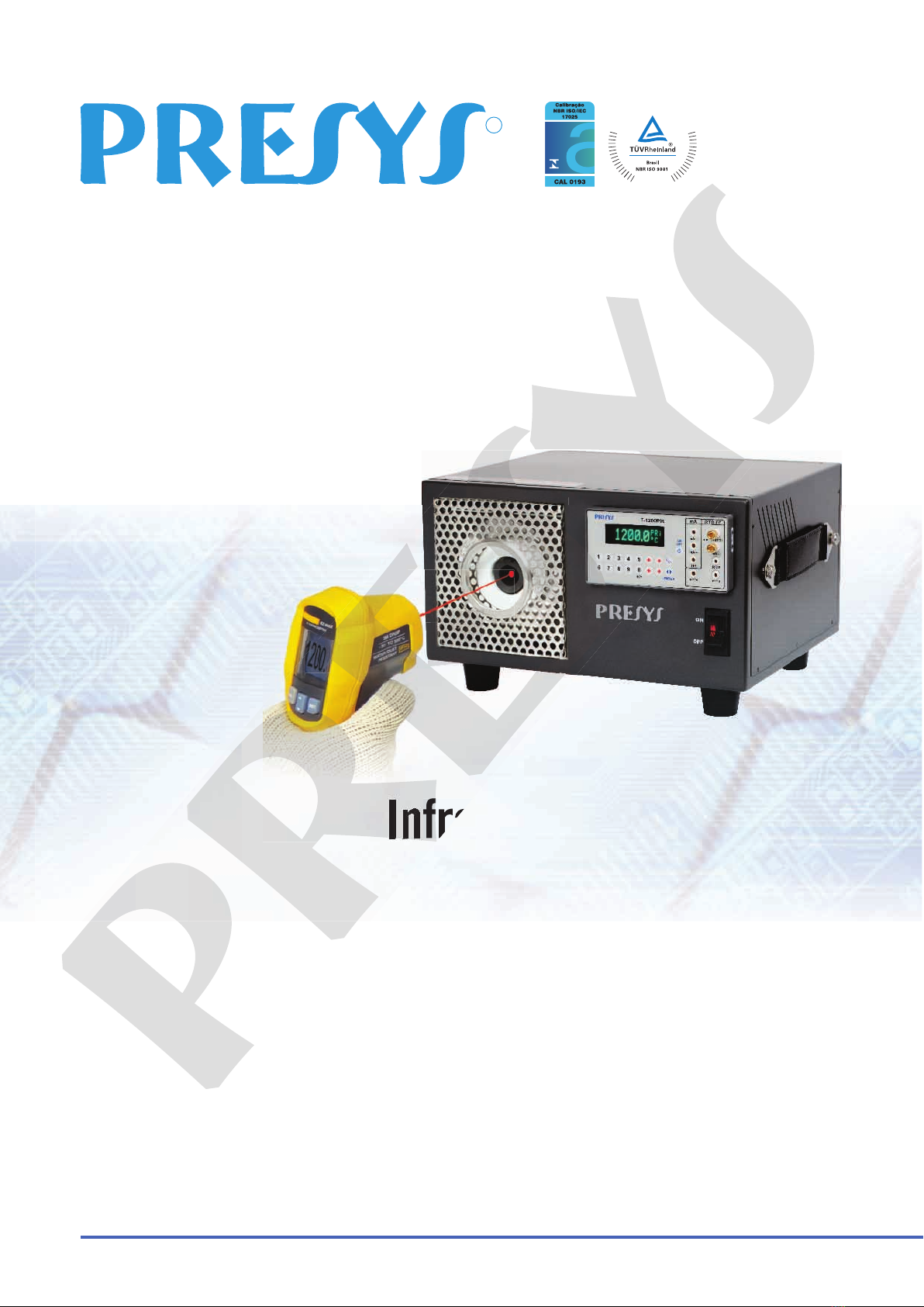
The Calibrator for Infrared Thermometer T-1200PIR generates temperature
values in order to enable the calibration of infrared thermometers. The temperatures
generated have high accuracy, in an area of uniform temperature and emissivity.
This calibrator also has input for thermocouples and resistance thermometers, as
well as current meter function. The T-1200PIR generates temperature from 50 to
1200 ºC.
Has input for thermocouples, RTDs and thermoswitches reading.
The use of external standard thermometer is not required*.
Carries out completely automatic calibrations with or without the use of a computer.
Accuracy of 3 ºC, 0.2 ºC stability and 0.1 ºC resolution.
Documenting capabilities: communication with computer and ISOPLAN Calibration
Software.
Portable and compact, has strap for easy transport.
*For higher performances, it is possible to make use of an external thermocouple sensor
type "N" connected to its own input.
It has extensive programming capabilities, where the calibrator is programmed to
generate pre-set temperature.
Compatible with automatic calibration and documenting software, with application
of ISOPLAN software on PC / Windows platform,using the serial port for connection
between the PC and the calibrator that communicate via RS-232 or RS-485. ISOPLAN
software can register thermometers and factory instruments, generate work orders,
produce and print calibration certificates and reports, that is, all the information of power
is brought into the environment of calibrations.
The Calibrator for Infrared Thermometer T-1200PIR generates temperature
presys
The Calibrator for Infrared Thermometer T-1200PIR generates temperature
values in order to enable the calibration of infrared thermometers. The temperatures
presys
values in order to enable the calibration of infrared thermometers. The temperatures
generated have high accuracy, in an area of uniform temperature and emissivity.
presys
generated have high accuracy, in an area of uniform temperature and emissivity.
This calibrator also has input for thermocouples and resistance thermometers, as
presys
This calibrator also has input for thermocouples and resistance thermometers, as
well as current meter function. The T-1200PIR generates temperature from
presys
well as current meter function. The T-1200PIR generates temperature from
Has input for thermocouples, RTDs and thermoswitches reading.
presys
Has input for thermocouples, RTDs and thermoswitches reading.
The use of external standard thermometer is not required*.
presys
The use of external standard thermometer is not required*.
Carries out completely automatic calibrations with or without the use of a computer.
presys
Carries out completely automatic calibrations with or without the use of a computer.
stability and 0.1
presys
stability and 0.1
resolution.
presys
resolution.
Documenting capabilities: communication with computer and ISOPLAN Calibration
presys
Documenting capabilities: communication with computer and ISOPLAN Calibration
Portable and compact, has strap for easy transport.
presys
Portable and compact, has strap for easy transport.
For higher performances, it is possible to make use of an external thermocouple sensor
presys
For higher performances, it is possible to make use of an external thermocouple sensor
type "N" connected to its own input
presys
type "N" connected to its own input
It has extensive programming capabilities, where the calibrator is programmed to
presys
It has extensive programming capabilities, where the calibrator is programmed to
generate pre-set temperature.
presys
generate pre-set temperature.
Compatible with automatic calibration and documenting software, with application
presys
Compatible with automatic calibration and documenting software, with application
of ISOPLAN software on PC / Windows platform
presys
of ISOPLAN software on PC / Windows platform
between the PC and the calibrator that communicate via RS-232 or RS-
presys
between the PC and the calibrator that communicate via RS-232 or RS-
software can register thermometers and factory instruments, generate work orders,
presys
software can register thermometers and factory instruments, generate work orders,
produce and print calibration certificates and reports, that is, all the information of power
presys
produce and print calibration certificates and reports, that is, all the information of power
is brought into the environment of calibrations.
presys
is brought into the environment of calibrations.