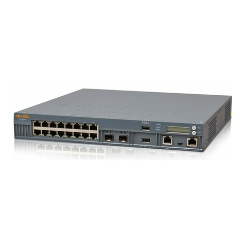
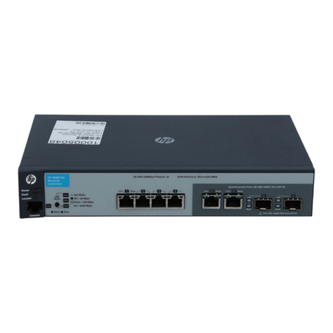
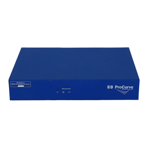
HP MSM720 User manual

HP MSM720 Controllers Installation Guide
Abstract
This document describes how to install and initially configure the MSM720 Controllers. This document applies to the MSM720
Access Controller (J9693A) and the MSM720 Premium Mobility Controller (J9694A). These products are hereafter referred to
as controller. See also the MSM7xx Controllers Configuration Guide.
HP Part Number: 5998-3789
Published: October 2013
Edition: 2

© Copyright 2013 Hewlett-Packard Development Company, L.P.
The information contained herein is subject to change without notice. The only warranties for HP products and services are set forth in the express
warranty statements accompanying such products and services. Nothing herein should be construed as constituting an additional warranty. HP shall
not be liable for technical or editorial errors or omissions contained herein.
Acknowledgments
Microsoft® is a U.S. registered trademarks of Microsoft Corporation.
Warranty
WARRANTY STATEMENT: See the warranty information sheet provided in the product box.

Contents
1 Identifying controller physical features...........................................................4
Unpacking the controller............................................................................................................4
Identifying front-panel features....................................................................................................4
Resetting to factory defaults........................................................................................................6
Using the console port..............................................................................................................6
2 Installing the controller................................................................................7
Installation procedures...............................................................................................................8
Installing optional accessories..................................................................................................15
3 Controller initial configuration....................................................................16
Perform initial configuration......................................................................................................16
Verify guest access (optional) ..................................................................................................18
4 Support and other resources......................................................................23
Online documentation.............................................................................................................23
Contacting HP........................................................................................................................23
HP websites...........................................................................................................................23
Typographic conventions.........................................................................................................23
A Specifications..........................................................................................24
Physical.................................................................................................................................24
Electrical...............................................................................................................................24
Environmental........................................................................................................................24
Acoustic................................................................................................................................24
Safety...................................................................................................................................24
Emissions...............................................................................................................................24
Immunity...............................................................................................................................24
Ethernet.................................................................................................................................25
Cabling and safety standards..................................................................................................25
Cabling specifications.............................................................................................................26
Cabling distance specifications................................................................................................26
B Mode conditioning patch cord (fiber cables)................................................28
Installing the patch cord..........................................................................................................28
C Regulatory information..............................................................................29
FCC Class A Notice................................................................................................................29
For Taiwan............................................................................................................................29
D Recycle statements....................................................................................30
Waste Electrical and Electronic Equipment (WEEE) statements......................................................30
Contents 3
1 Identifying controller physical features
Unpacking the controller
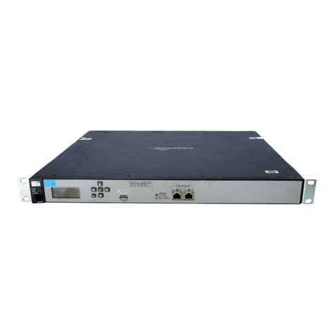
Unpack your controller and verify that you have received these items:
•Controller
•External AC/DC power adapter
•AC/DC power adapter power cord (for your region)
•Console port serial cable (DB-9 to RJ-45)
•Documentation including Safety and Regulatory information
•Software License, Warranty, and Support information
•Accessory kit comprised of:
Two wall-mount brackets◦
◦Two 19-inch rack-mount adapter brackets with four rack-mount screws
◦Eight bracket screws (used with both bracket types)
◦Four rubber feet (for tabletop installation)
◦Cable tie for power cord
Identifying front-panel features
It is important to be aware of the controller front panel features as they are referenced throughout
this document.
Figure 1 Controller front-panel features
1 2
7
3
5 6 8
4
5. Console port1. Power, Fault, and Locator LEDs
6. Test LED2. LED Mode select button and Mode indicator LEDs
7. Reset and Clear buttons3. Four 10/100/1000 ports
8. Port LEDs: Link (left), Mode (right)4. Two dual-personality ports (RJ-45 or mini-GBIC)
4 Identifying controller physical features

Network ports
•Access network: Four auto-sensing 10/100/1000Base-T ports. All these ports have the
Auto-MDX feature, which means that you can use either straight-through or crossover twisted-pair
cables to connect any network devices to the controller.
•Internet network: Two dual-personality ports for either 10/100/1000Base-T RJ-45 (Auto-MDX)
uplinks, or optional mini-GBIC (SFP) slots for fiber uplinks.
LEDs
There are three groupings of LEDs on the controller:
•Status LEDs (Table 1 (page 5))
•Port LEDs (Table 2 (page 5))
•Port LED Mode indicator LEDs (near the Mode selector button) (Table 3 (page 6))
Table 1 Status LEDs
MeaningStateStatus LEDs
The controller is powered on.OnPower (green)
No power connection. The controller is NOT receiving power.Off
The controller is beginning its boot sequence. Turns on for three seconds at power
up or reset.
OnFault (orange)
The Locator LED is used to locate a specific MSM720 in an area full of other
controllers and MSM720s. The LED can be set to be on solid or blink for a
OnLocator (blue)
Blinking specified number of minutes (1-1440). The default is 30 minutes. Use the command
“chassislocate”.
Off
The normal operational state; the controller is not undergoing self test.OffTest (green/orange)
Lights during power up self test and stays on until the controller is ready to receive
traffic.
On (green)
Port LEDs
The port LEDs provide information about the individual ports.
Table 2 Port LEDs
MeaningStateStatus LEDs
Port LEDs
The port is enabled and receiving a link indication from the connected device.OnLink (green)
One of these condition exists:Off
•No active network cable is connected to the port
•The port is not receiving link beat or sufficient light
•The port has been disabled through the controller console, the Web browser
interface, HP Manager, or other network management tool
Indicates Activity, Duplex, or Speed according to Mode selected. See “LED mode select button
and indicator LEDs” (page 6) for details.
Mode (green)
Mini-GBIC LEDs
Identifying front-panel features 5

Table 2 Port LEDs (continued)
MeaningStateStatus LEDs
One of the following conditions exist:Blinking
(green)
Link
•The mini-GBIC is not supported by the current software
•The mini-GBIC is not a genuine HP Mini-GBIC and is not supported
•The mini-GBIC is an “A” version in a controller that requires a “B” version or
later
Both the Link and Mode LED turn on solid for 2 seconds and then go to normal
operation. This indicates the mini-GBIC has been recognized by the controller.
On for 2
seconds
Link and Mode (green)
LED mode select button and indicator LEDs
The Port Mode LED shows Activity (Act LED on), Duplex (FDx LED on), or Speed (Spd LED on). Press
the LED Mode Select button to sequence through the three modes.
Figure 2 LED mode select button and LEDs
1 3 42
3. Port Link LED1. LED Mode Select button
4. Port Mode LED2. Mode Indicator LEDs (Act, FDx, Spd)
Table 3 Port LED mode indicator LEDs
MeaningMode
The Port Mode LED displays network activity.Act
The Port Mode LED is on when the port is in full-duplex mode.FDx
The Port Mode LED indicates port speed. If the Port Mode LED is off, the port is operating at 10 Mbps. if the
Port Mode LED is blinking, the port is operating at 100 Mbps. If the Port Mode LED is on continuously, the
port is operating at 1000 Mbps.
Spd
Resetting to factory defaults
To reset the controller to its factory default configuration:
1. Using a paperclip, press and release the Reset button.
2. Immediately press and hold the Clear button until the LEDs above the Clear button blink three
times, then release the Clear button.
Using the console port
The Console port is used to connect a console to the controller by using the supplied RJ-45 to DB9
cable. This is used for the CLI (Command Line Interface). See the MSM7xx Controllers CLI Reference
Guide.
6 Identifying controller physical features

2 Installing the controller
WARNING!
•For indoor use only. The controller, AC power adapter, and all connected cables are not
designed for outdoor use.
•The HP mini-GBICs are Class 1 laser devices. Avoid direct eye exposure to the beam coming
from the transmit port.
•The rack or cabinet should be adequately secured to prevent it from becoming unstable and/or
falling over.
•Devices installed in a rack or cabinet should be mounted as low as possible, with the heaviest
devices at the bottom and progressively lighter devices installed above.
•Wall-mount the controller with network ports facing up (away from the floor). Do not wall-mount
the controller with the network ports facing down (toward the floor) or ventilation ducts facing
up or down.
•LAN cables may occasionally be subject to hazardous transient voltages (such as lightning
or disturbances in the electrical utilities power grid). Handle exposed metal components of
the network with caution.
CAUTION:
•Use only the AC/DC power adapter supplied with the controller for connection to an AC
power source.
•Ensure the power source circuits are properly grounded, then use the power cord supplied
with the controller to connect it to the power source.
•Use only the AC/DC power adapter and power cord supplied with the controller. Use of other
adapters or improper power cords, including those that came with other HP Networking
products, may result in damage to the equipment.
•If your installation requires a different power cord than the one supplied with the controller,
ensure the cord is adequately sized for the controller’s current requirements. In addition, be
sure to use a power cord displaying the mark of the safety agency that defines the regulations
for power cords in your country. The mark is your assurance that the power cord can be used
safely with the controller. If the supplied power cord does not fit, contact HP Networking
support.
•When installing the controller, the AC outlet should be near the controller and should be easily
accessible in case the controller must be powered off.
•Do not install the controller in an environment where the operating ambient temperature might
exceed 45°C (113°F). This includes a fully-enclosed rack. Ensure the air flow around the sides
and back of the controller is not restricted.
•Hot swapping transceivers is supported. You can install or remove a transceiver with the
controller powered on, a reset will not occur. However, rapid hotswaps are not recommended.
Wait a few seconds for the Mode LED to turn on (during initialization) and then turn off.
•Use only supported genuine HP mini-GBICs with your controller. Non-HP mini-GBICs are not
supported and their use may result in product malfunction. Should you require additional HP
mini-GBICs, contact your HP Networking Sales and Service Office or authorized dealer.
7

CAUTION:
•Ensure all port covers are installed when the port is not in use.
•There are no user-serviceable parts inside these products. Any servicing, adjustment,
maintenance, or repair must be performed only by service-trained personnel.
•These products do not have a power switch; they are powered on when the power cord is
plugged in.
Installation procedures
These steps summarize your controller installation. The rest of this chapter provides details on these
steps.
•“Prepare the installation site” (page 8). Make sure the physical environment into which you
will be installing the controller is properly prepared, including having the correct network
cabling ready to connect to the controller and having an appropriate location for the controller.
•“Verify the controller passes self test” (page 8). Plug the controller into a power source and
observe that the LEDs on the controller front panel indicate correct controller operation.
•“Mount the controller” (page 10). The controller can be mounted in a 19-inch telco rack, in
an equipment cabinet, on a wall, or on a horizontal surface.
•“Connect the controller to a power source” (page 12). Once the controller is mounted, plug
it into the main power source.
•“Connect the network cables” (page 13). Using the appropriate network cables, connect the
network devices to the controller ports.
•“Installing or removing optional mini-GBICs” (page 13). The controller has two slots for installing
mini-GBICs. Depending on where you install the controller, it may be easier to install the
mini-GBICs first.
Prepare the installation site
•Ensure the cabling infrastructure meets the necessary network specifications.
•Before installing the controller, plan its location and orientation relative to other devices and
equipment:
◦In front of the controller, leave at least 7.6 cm (3 inches) of space for the twisted-pair and
fiber-optic cabling
◦Behind the controller, leave at least 3.8 cm (1 1/2 inches) of space for the power cord.
◦On each side of the controller, leave at least 7.6 cm (3 inches) for cooling.
Verify the controller passes self test
1. Before mounting the controller in its network location, verify that it passes its self test.
2. Connect the AC/DC adapter’s power cord to the power connector on the back of the controller
and then plug the AC/DC power adapter into a nearby properly grounded electrical outlet.
8 Installing the controller

Figure 3 Connecting the power cord
CAUTION: Use only the AC/DC power adapter and power cord supplied with the controller.
Use of other adapters or power cords, including those that came with other HP Networking products,
may result in damage to the equipment.
NOTE: The controller does not have a power switch. It is powered on when the external AC/DC
power adapter is connected to the controller and the adapter power cord is connected to a power
source. The external AC/DC power adapter automatically adjusts to any voltage between 100-240
volts and either 50 or 60 Hz. The MSM720 cannot be powered by Power over Ethernet (PoE).
Check the LEDs on the controller as described below.
Figure 4 LEDs
1 3 42
3. Port LED: Link1. Power, Fault, and Locator LEDs
4. Port LED: Mode2. Test LED
When the controller is powered on, it performs a self test.
Installation procedures 9

LED behavior
During the self test:
•Initially, all the controller and port LEDs are on. Most of the LEDs turn off and then may turn
on again during phases of the self test.
•For the duration of the self test, the Test LED stays on.
When the self test completes successfully:
•The Power LED remains on.
•The Fault, Locator and Test LEDs stay off.
•The Act LED remains on indicating the default port LED mode.
•The port LEDs on the front of the controller go into their normal operational mode:
If the ports are connected to active network devices, the Link LEDs stay on and the Mode
LEDs behave according to the mode selected. In the default mode (Act), the Mode LEDs
blink to indicate port activity.
◦
◦If the ports are not connected to active network devices, the Link and Mode LEDs will stay
off.
Mount the controller
After the controller passes self test, it is ready to be mounted in a stable location. The controller
can be mounted in these ways:
•In a rack or cabinet
•On a horizontal surface
•On a wall
Rack or cabinet mounting
The controller is designed to be mounted in any EIA-standard 19-inch telco rack or communication
equipment cabinet. The controller can also be mounted in a cabinet with the provided brackets.
Note that the mounting brackets have multiple mounting holes and can be rotated allowing for a
wide variety of mounting options. Secure the rack in accordance with the manufacturer's safety
guidelines.
NOTE: The 12-24 screws supplied with the controller are the correct threading for standard
EIA/TIA open 19-inch racks. If installing the controller in an equipment cabinet such as a server
cabinet, use the clips and screws that came with the cabinet in place of the 12-24 screws that are
supplied with the controller.
NOTE: Optional accessories have to be mounted at the same time as the mounting brackets.
See “Installing optional accessories” (page 15).
10 Installing the controller

1. Use a #1 Phillips (cross-head) screwdriver and attach the mounting brackets to the controller
with the included 8 mm M4 screws.
Figure 5 Attaching mounting brackets
WARNING! For safe reliable installation, only use the screws provided in the accessory kit
to attach the mounting brackets to the controller.
NOTE: The mounting brackets have multiple mounting holes and can be rotated allowing
for a wide variety of mounting options. These include mounting the controller so that its front
face is flush with the face of the rack, or mounting it in a more balanced position.
2. Hold the controller with attached brackets up to the rack and move it vertically until rack holes
line up with the bracket holes, then insert and tighten the four number 12-24 screws holding
the brackets to the rack.
Figure 6 Mounting in a rack
Wall mounting
WARNING! The network ports must be facing up. Do not mount the controller with ports facing
down.
CAUTION: The controller should be mounted on a wall or wood surface that is at least 12.7 mm
(1/2 inch) plywood or its equivalent.
1. Use a #1 Phillips (cross-head) screwdriver and attach the mounting brackets to the controller
with the included 8 mm M4 screws.
Installation procedures 11

2. Attach the controller to the wall or wood surface with two 15.9 mm (5/8 inch) number 12
wood screws (not included).
Figure 7 Wall mounting the controller
Using on a table
For table top use, attach the provided rubber feet to the four underside corners of the controller.
To reduce risk of someone tripping on the cables, consider anchoring the cables to a table leg.
CAUTION: Ensure the air flow is not restricted around the sides and back of the controller.
Using a Kensington security cable
To prevent unauthorized removal of the controller, you can use a Kensington Slim MicroSaver
security cable (not included) to attach the controller to an immovable object.
Figure 8 Using a security cable
Connect the controller to a power source
1. Plug the AC/DC adapter’s power cord into the controller and then plug the AC/DC power
adapter into a nearby AC power source.
2. Re-check the LEDs during self test. See “LED behavior” (page 10).
12 Installing the controller

3. Secure the power cord to the controller with the provided cable tie.
Figure 9 Securing the power cord to the controller
1
2
3
3. Cable tie anchor2. Cable tie1. Power cable
Connect the network cables
Connect the network cables from the network devices or patch panels to the controller.
Using the RJ-45 connectors
To connect:
Push the RJ-45 plug into the RJ-45 port until the tab on the plug clicks into place. The Link LED lights
when the devices at either end of the cables are powered on.
To disconnect:
Press the small tab on the plug and pull the plug out of the port.
Installing or removing optional mini-GBICs
You can install or remove an optional mini-GBIC from a mini-GBIC slot without having to power
off the controller. Use only HP mini-GBICs.
Mini-GBIC information
Dual-personality ports use either the 10/100/1000Base-T RJ-45 connector, or a supported HP
mini-GBIC (Small Form Factor Pluggable (SFP)) for fiber-optic connection. By default, the RJ-45
connectors are enabled.
The optional mini-GBICs add support for these speeds and technologies:
Table 4 Optional network speeds and technologies
Cabling*TechnologySpeed
Fiber (multimode)100-FX100 Mbps
Fiber (single mode)100-BX
Fiber (multimode)1000-SX1 Gbps
Fiber (multimode or single mode)1000-LX
Fiber (single mode)1000-LH
Fiber (single mode)1000-BX
*See also “Cabling and safety standards” (page 25).
Installation procedures 13

The controller supports these mini-GBICs:
•HP X112 100M SFP LC BX-D Transceiver J9099B
•HP X112 100M SFP LC BX-U Transceiver J9100B
•HP X111 100M SFP LC FX Transceiver J9054B
•HP X121 1G SFP LC SX Transceiver J4858C
•HP X121 1G SFP LC LX Transceiver J4859C
•HP X122 1G SFP LC BX-D Transceiver J9142B
•HP X122 1G SFP LC BX-U Transceiver J9143B
•HP X121 1G SFP LC LH Transceiver J4860C
CAUTION: Hot swapping of transceivers is supported. You can install or remove a transceiver
with the controller powered on, a reset will not occur. However, rapid hotswaps are not
recommended. Wait a few seconds for the Mode LED to turn on (during initialization) and then
turn off.
CAUTION: Use only supported genuine HP mini-GBICs with your controller. Non-HP mini-GBICs
are not supported and their use may result in product malfunction. Contact your HP Networking
Sales and Service Office or authorized dealer for additional HP mini-GBICs.
NOTE:
•The mini-GBIC slots are shared with 10/100/1000Base-T RJ-45 ports. When a mini-GBIC is
installed in a slot, the associated RJ-45 port is disabled and cannot be used.
•Ensure the fiber network cable is NOT connected when you install or remove a mini-GBIC.
Installing the mini-GBICs
Remove the protective plastic cover and retain it for later use. Hold the mini-GBIC by its sides and
gently insert it into either of the slots on the controller until the mini-GBIC clicks into place.
WARNING! The HP mini-GBICs are Class 1 laser devices. Avoid direct eye exposure to the laser
beam coming from the transmit port.
14 Installing the controller

Figure 10 Installing a mini-GIBIC
2
3
1
3. Wire bail2. Mini-GBIC1. Mini-GBIC Slot
Removing the mini-GBICs
NOTE: You should disconnect the network cable from the mini-GBIC before removing it from the
controller.
Depending on when you purchased your HP mini-GBIC, it may have one of three different release
mechanisms: a plastic tab on the bottom of the mini-GBIC, a plastic collar around the mini-GBIC,
or a wire bail.
To remove the mini-GBICs that have the plastic tab or plastic collar, push the tab or collar toward
the controller until you see the mini-GBIC release from the controller (you can see it move outward
slightly), and then pull it from the slot.
To remove the mini-GBICs that have the wire bail, lower the bail until it is approximately horizontal,
and then using the bail, pull the mini-GBIC from the slot.
Replace the protective plastic cover on the mini-GBIC.
Installing optional accessories
Two optional controller accessories are available from HP.
HP X510 1U Cable Guard (J9700A): Mounts to the front of the controller to help stabilize and
support the networking cables and provide extra security against tampering or theft.
HP X520 1U Power Adapter Shelf (J9701A): Holds the power supply adapter at the back of the
controller.
Install these optional accessories according to the instructions provided with them. Accessory
documentation is available online (search by product number).
Installing optional accessories 15

3 Controller initial configuration
Perform initial configuration
NOTE: A factory-default controller is assumed. Ports 1 to 4 are available at 192.168.1.1.
NOTE: Do not connect power or network cables to the controller until directed to do so in this
procedure. If cables are connected, temporarily disconnect them.
To initially configure the controller:
1. Configure your computer to use a static IP address in the range 192.168.1.2 to 192.168.1.254
and set the subnet mask to 255.255.255.0. Set the default gateway to 192.168.1.1 and DNS
server to 192.168.1.1.
2. Connect network cables as follows:
a. Disconnect any cable from your computer Ethernet ports and disable any wireless
connection.
b. Connect controller port 1 (ports 2 to 4 can also be used) (the Access network) to your
computer Ethernet port.
c. Connect controller port 5T or 6T (or if enabled, port 5S or 6S) (the Internet network) to
a network with Internet access or to the PC port of a DSL modem or equivalent.
3. Power on the controller and wait approximately 90 seconds until the Test LED turns off.
4. Perform initial login tasks:
a. Using Microsoft Internet Explorer 8+ or Mozilla Firefox 3+, open page:
https://192.168.1.1.
b. A security certificate warning may be displayed the first time you connect to the
management tool. This is normal. Select whatever option is needed in your Web browser
to continue to the management tool.
c. On the Login page, enter admin for Username and admin for Password and then select
Login.
d. On the HP End User License Agreement page, read the agreement and then select Accept
HP End User License Agreement.
e. On the product registration page it is recommended that you register your product now
by selecting Register Now. If the controller is not connected to the Internet or you prefer
not to register now, select Register Later. Registration is available at any time by selecting
Maintenance > Registration.
f. In some regions, a Country prompt appears. Choose the country in which this product
will be used and select Save.
CAUTION: To maintain regulatory compliance, the country must be set accurately to
the country in which the controller and any controlled access points (APs) will operate.
g. At the Administrator password prompt it is recommended that you change the password.
Select Save to save the new password or Cancel if you choose to keep the default
password.
16 Controller initial configuration

5. Follow the Configure initial controller settings workflow.
a. It is highly recommended that you follow the Configure initial controller settings workflow.
This workflow is selected by default. Select Start to launch this workflow. If you choose
not to run a workflow at this time, select the Home button to exit the workflow page.
b. The Configure initial controller settings workflow provides instructions and prompts you
for options. Read the instructions and respond to the prompts as desired, selecting Next
to get to the next workflow page. Context-sensitive online help is also available for each
page of the workflow.
c. The last page in the workflow lists all configuration settings that will be applied. For
example:
Perform initial configuration 17

Review the settings before you select Apply to save and activate the new configuration
on the controller. Alternatively, select Back to go to the previous workflow page or select
Cancel to discard your workflow settings and exit the workflow.
d. After applying your changes, a confirmation page appears showing the menu paths to
each configuration page associated with the Configure initial controller settings workflow.
For example:
e. If desired, select a page link to make additional configuration changes and then select
Automated workflows above the Network Tree to return to this page.
f. Select Done.
g. If desired, start one of these other workflows:
•Create a wireless network for employees: This workflow helps you create a new
wireless network to provide wireless access for employees. It lets you define how
employee traffic will be distributed onto your wired infrastructure and configure
wireless security settings to safeguard network traffic.
•Create a wireless network for guests: This workflow helps you create a new wireless
network to provide wireless access for guests. It lets you define how guests will be
authenticated (using a RADIUS server or the local user accounts feature on the
controller) and how guests will receive an IP address.
Caution: When using teaming, you must not use this workflow. Instead, you must
manually configure guest access as described in the
MSM7xx Controllers Configuration
Guide
under “Guest access and teaming”.
h. Select any menu to exit the workflow.
Verify guest access (optional)
Although optional it is recommended that you perform a simple verification of the guest access
interface using a local guest account. This verification uses the Create a wireless network for guests
workflow. Sample values are used. Substitute your own values if desired.
18 Controller initial configuration

Configure basic guest access
1. To configure basic guest access, follow the Create a wireless network for guests workflow.
Select Start to launch this workflow.
2. On the Create a new wireless network for guests page, in Wireless network name (SSID) enter
Guests, then select Next.
3. On the Configure guest authentication page, select the Use the user account feature on the
controller option, then set both Username and Password to guest1. Leave all other options at
their defaults, then select Next.
Verify guest access (optional) 19

4. On the Guest DHCP addressing page, select DHCP server.
a. Define the DHCP server IP address range:
•Set Start address to 192.168.1.1
•Set End address to 192.168.1.254
•Set Netmask to 255.255.255.0
NOTE: The first address in the range is reserved for the controller gateway and DNS
(192.168.1.1 in this example). The DHCP server assigns addresses to clients at Start
address +1, (192.168.1.2 in this example).
b. Select Next.
5. On the Apply guest access settings to your APs page, select Next to accept the defaults.
6. The last page in the workflow lists all configuration settings that will be applied.
20 Controller initial configuration
Other manuals for MSM720
3
This manual suits for next models
1
Table of contents
Other HP Controllers manuals

HP
HP Smart Array P430 User instructions

HP
HP Aruba 7010 Series User manual

HP
HP ProCurve MSM760 User manual

HP
HP 8169A User manual

HP
HP StorageWorks 2312 User manual

HP
HP 9000 Series 300 User manual

HP
HP Smart Array P212 User manual

HP
HP Smart Array E500 Controller User instructions

HP
HP StorageWorks HSG60 User manual

HP
HP B120i User manual