TIANJIN BAILI ERTONG MACHINERY QBR3 User manual

(Please read this Operation Manual carefully before using thisproduct) SM-20
QBR3~QBR5
Quarter-turn Electric Valve Actuator
Operation Manual
Tianjin Baili Ertong Machinery Co.,Ltd
(Former Tianjin No.2 General Machinery Factory)

Content
1. Product instruction.................................................................................................1
2. Electric wiring.........................................................................................................2
3. Product adjusting....................................................................................................3
4. Additional Instruction for Explosion-proof product...........................................4
5. Comprehensive test and notice...............................................................................5

1
1. Product instruction
1.1 Summary
QBR3~QBR5 are quarter-turn electric valve actuators (hereinafter referred to as Electric actuator)
invented by our Company. ThisseriesareclassifiedintoQBR3, QBR4, QBR5 according to the seating
numbers. Control torque ranges from 600 Nm to 12000Nm. This series can be operated with ball valve,
butterfly valve whose disc can make a 90°turn, combining an electric valve actuator which controls valve
open and close. Both single unit control and collective-remote control can be realized. Remote electric
control and manual operation, electric operation on site can also be realized. This series can be largely
applied in pipe and valve industrial field.
This explosion-proof grade for the explosion-proof type product (with Ex) is ExdIIBT4Gb.
1.2Technicalparameters
1.2.1 This product is in accordance with GB/T24923-2010《Technical Conditions of Basic Type of Electric
Actuator》, and GB/T24922-2010《Technical Conditions of Explosion-proof Type of Electric Actuator》.
1.2.2 Power supply: 380V, 50Hz, 3-phase 4-wire system, sine AC; 380V, 50Hz, 3-phase 3-wire system,
sine AC (For special voltage and frequency, please refer to product’s nameplate and contract.).
1.2.3 Protection class: IP67.
1.2.4 Ambient temperature: -20~+70℃.
1.2.5 Relative humidity: be up to 90%(when at 25℃).
1.2.6 Altitude: be up to 1000m.
1.2.7 Short-time duty: 10mins (rated time).
1.2.8 Applicable working environment: for basic type, no severe vibration and no strong corrosive medium
and explosive mixed gas in the operating environment; for explosion-proof type, no strong corrosive
medium.
1.2.9 Electric port: total number of M33×1.5 is 2;
1.3Majorstructureandfunction:
1.3.1 Motor: YDF specialized electric valve motor. This kind of motor complies with
relatednationalstandardanditstorqueperformancecomplieswithvalve’sloadingperformance.
1.3.2Reducermechanism: it applies first-class spur gear, first-class worm gear, and first-class NN type
planetary reducer.
1.3.3Limitcontrolandpositionindicator: this mechanism is led by out put shaft(90°turns),limit cam,
pointer(90rotationinonetravel) .Potentiometerisusedtocontrolremoteelectricalsignal,applyingstep-upgearingt
otransfer.(RefertoFig.1)
1.3.4 Torque control mechanism: it controls the valve according to the output torque set by the electric
actuator, both in valve open and close direction. Torque signal comes from a axial movement from which
electrical worm compresses belleville spring. Torque switches are made of cams.(see Fig.2)
1.3.5 Manual operation mechanism: manual-electrical switch is automatic. To turn the handwheel while in
manual operation without switching. Due to QBR5 outputs a big torque value, to add a NGW planetary
reducer on the manual worm so as to minimize the handwheel’s force.
1.3.6 Spline joint head: one of QBR serial feature is that spline joint head is mounted in the output shaft,
which is suitable for the electric actuator to mount on valve in multi-angle. It is easy to be removed and it
can assist the processing of the stem’s key slot. The spline joint head is suitable for the mounting of valve
and quarter-turn electric actuator which has mechanical limit output shaft. (The output shaft of this series
has mechanical limits both on open and close position.)
1.3.7 Local control buttons: local control buttons, at one side of the handwheel, are responsible for

2
actuator’s electrical control on site.
1.4 Mounting position of the electric actuator
2. Electrical wiring
For user’s convenient, please see the attached documents for Electrical Schematic Diagram, Wiring
contacts table and Electric components table.
2.1 Electric wiring steps for the General type of actuator (non-explosion proof )
2.1.1 First, open the case cover; put power cable and control cable respectively through “wiring inlet
structure” and into the control case. Please see Fig.3 for wiring inlet structure.
2.1.2 According to the Electric schematic diagram, Terminal Numbers and Electric Schematic Wiring’s
number, connect each core wire with terminals . It should be reliable and cannot be exposed to the outside.
2.1.3 Gently pull the cable out so as to ensure that the cable will not influence other working parts in the
control case.
2.1.4 Put the sealing ring and gasket into the case’s screw hole; rotate gland nut and compress sealing ring,
so as to make it closely contact with cable’s edge.
2.1.5 Inner grounding and external grounding should be fixed and reliable.
2.2 Wiring steps for explosion-proof type of electric actuator (see Fig.4)
2.2.1 Remove No.1 gland nut, and take No.2-No.4. Now, No.3 gasket used for sealing is useless.
2.2.2 Open No.5 wiring box case.
2.2.3 Put power cable and control cable respectively through No.1, No.2, No.4 and No.2 (see Fig.4)
2.2.4 Put cable’s end into wiring box’s inlet hole; put the lug plate on each core wire; lug plate and the core
wire should be fastened.
2.2.5 Connect each core wire with corresponding contacts according to the electric schematic wiring
diagram.
2.2.6 Push every component on the cable into the wiring box’s inlet hole and gently pull the cable outward,

3
so as to ensure the cable’s rubber jacket is in the hole of the “sealing plug”.
2.2.7 Screw the gland nut to compress the sealing rubber plug and make it combine firmly with cable’s
rubber jacket. Connect the grounding core wire of the cable with the inner grounding screw of the wiring
box.
2.2.8 Put on the wiring box case.
2.2.9 Connect the actuator’s external ground, and it should be reliable and safe.
2.2.10 The design service life of actuator is 8000 times.
2.2.11 According to the regulations on the recycling and treatment of waste electrical and electronic
products, please comply with the relevant national regulations and properly dispose of waste products. Or
call our after-sales service department for recycling. Tel: 022-26740033.
2.3 Cable shall be correctly connected to avoid the rain leaking into the electric actuator
(the first two connection patterns are right in the following picture.)
3. Product adjusting
★The torque mechanism has been tested and set up before delivered from the factory. It complies with the
maximum torque value written on the nameplate. User does not need to readjust. (see Fig.2) Besides, fasten
two mechanical limit screws on the main case body. It is better not to unscrew the mechanical limit screws
if there is no special condition.
★Potentiometer’s gear and potentiometer shall be loosened in case of any damage to the potentiometer.
★The cam on the limit control mechanism is Closing Cam. OPEN and CLOSE have been marked on the
torque control mechanism.
3.1 The adjustment for the limit control mechanism (including adjustment for positioner
and potentiometer.)
A. Make the valve at the middle position.
B. Start the motor and then make sure if the rotation direction of the valve is right while it is of
electric-driven. If wrong, change power phase sequence.

4
C. Manually close the valve; loosen the screw on the Closing Cam; in the direction of valve closing, to
rotate the cam until a “crack” sound is heard, fasten the screws on the cam.
D. Manually open the valve, making the Closing Cam to be away from micro switch’s contact. Then,
electrically close the valve to check if valve’s closing position is precise. With a precise limit position and a
sensitive control, user can fasten the screw on the Closing Cam. Loosening the screw is forbidden.(To
adjust the cam if there is error with valve’s closing position and repeatedly check until requirement is met.)
Adjustment for the closing position of valve.
E. Manually operate the valve to the fully open position and unscrew the screw on the Open Cam; turn the
cam to contact micro switch in the direction of opening valve as long as a “crack” sound is heard, user can
fasten screw. (The steps below are the same with “D” and be care of the direction.)
F. Electrically operate the valve for one stroke to make sure the controlling is in good condition. Check
again if the screws on the cams are fastened firmly. Till now, adjustment for open stroke and closing stroke
are finished. (See Fig.1)
3.2Adjustment for the pointer and potentiometer
A. When the valve is at a limit position, unscrew the pointer’s screws to have it pointed at the
corresponding scale and then fasten the screw. See Fig.1
B. When the valve is at a limit position(fully open or closed), uplift the potentiometer’s gear to make it to
be separated. Then, fasten the screws; rotate the potentiometer to the corresponding valve position
(potentiometer rotates to the end position) and go back a little. Unscrew the screw on the potentiometer’s
gear and make it to be meshed. To confirm it is meshed before fasten the screw.(Take care of the limit
position ,or it would be damaged.)
3.3Adjustment for the mechanical limit screws
A. To make sure in which valve position the screw limits before adjusting the mechanical limit screw.
While turning the valve right is to close, the limit screw on the right side is closing limit and the limit screw
on the left side is open limit.
B. When the valve is adjusted on a limit position, rotate the screws inward until it touches the upper part of
the driving shaft, and then, rotate back for 0.5-1 turn. Finally, fasten the outside screw and nut. Till now,
adjustment for mechanical limit is finished.
4. Additional Instruction for Explosion-proof product
4.1 Instruction for explosion-proof type
QBR3Ex-QBR5Ex series explosion-proof type is produced on the basis of GB3836.1-2010《General
Requirement for the Equipment Used in Explosive Environment, Part I》and GB3836.2-2010 《The
Equipment Protected by Explosion-proof Enclosure “d” Used in Explosive Environment, PartII》.
Meanwhile, this series have been tested, experimented and finally verified by the national verified
explosion-proof organization and get Conformity Certificate of Explosion-Proof.
The explosion-proof grade of QBR explosion-proof type is Ex d II B T4 Gb. Ex d II B T4 Gb---Class
IIB, Temperature T4,Electrical apparatus. The sign “Ex” shows that the electric apparatus comply with the
Explosion-proof Standard; “d” shows that the explosion-proof type is enclosure explosion-proof; II class
represents that electric apparatus used in explosive gas environment except for gas made from coal; II B
represents that the gas is ethylene; T4 indicates that the permissible surface temperature is 135℃;Gb is
apparatus protection degree.
There are 3 seating numbers and 6 types of this product: QBR3Ex、QBR3Ex.IN、QBR4Ex、
QBR4Ex.IN、QBR5Ex、QBR5Ex.IN.

5
4.2 Notice for usage and maintenance:
4.2.1 Power must be cut off when actuator’s any cover is open.(please see the warning plate: “Forbid to
open the box cover when the power is on.”)
4.2.2 Forbid to hit the openness window by using hard materials.
4.2.3 Keep the nameplate and warning plate being fixed on actuator and the words on them should be
recognized.
4.2.4 Don’t open the electric box cover outdoors in rainy day or windy day.
4.2.5 The product’s explosion-proof cover cannot be knocked or scratched during maintenance or
debugging.
4.2.6 Apply anti-rust painting 204-1 after debugging or maintenance and before assembling.
4.2.7 Please notify the company to change the broken explosion-proof elements. The products cannot be
powered on until it is renewed with qualified element.
4.2.8 Fasten the screws on the control box cover and wiring box cover after product debugging . After some
strong vibration, please make regular check to make sure whether it is reliable. Sealing structure cannot be
damaged at the same time. Tightness should be confirmed.
4.2.9 O-ring shall be kept properly. If damaged, change for a new one as soon as possible.
4.2.10 External grounding shall be safe and sound.
4.2.11 Connect the actuator’s external ground, and it should be reliable and safe.
4.3 Notice for the electric schematic diagram and electrical wiring
Besides the Manual Operation, a copy of electric schematic diagram has been provided. User shall
strictly follow the terminal diagram while wiring. Wiring lug shall be applied. The wiring lug shall not
exposed or loosened. Uplift the plastic jacket of the wiring lug(same direction ) to make sure an appropriate
leakage distance. Any electric conductor cannot be left in the wiring case.
5. Comprehensive test and notice
5.1 Comprehensive test
5.1.1 When manually operate the valve for one travel, check if the pointer and stroke transmission work
well and also check the performance of manual operation.
5.1.2 Electrically operate the valve to the fully-closing position. The limit control mechanism shall be
sensitive. The Close Indicator will light up and pointer will points to “0” at that time.
5.1.3 Electrically operate the valve to the fully-open position. The limit control mechanism shall be
sensitive and is able to open the valve. The Open Indicator will light up and pointer points to “100”at that
time.
5.2 Notice
5.2.1 Fasten the screw on the control case after product adjustment. Sealing components shall be kept well
so that outdoor performance of the product can be ensured.
5.2.2 After maintenance, user shall check if limit control mechanism, position indicator and torque control
mechanism comply with requirements. Readjustment shall be made if possible.
5.2.3 The sealing plug would be damaged if it is used after several times of dismounting. In this case, user
can purchase from manufacturer or produce according to required dimensions.

Special Warning
In order to ensure the protective performance of the case of the whole electric actuator,
users must strictly follow the requirements in the Operation Manual and in this Special
Cautions while performing relevant operations when they set and service the actuators. If
users failed to follow the regulations in the Operation Manual and the Special Cautions while
performing relevant operation and have resulted in fail-safe protection of the case of the
electric actuators, the users shall bear the responsibility.
Before delivery all locations related to case protection of the products have been strictly
inspected to ensure that the case is airtight. If users need to open the following locations for
setting, service or any other reasons:
1.Case of control box
2.Case of wiring box
3.Wire outlet plug
At places where wire comes in and goes out, it must be ensured that:
1. There is no affect of adverse elements such as rain, snow, hail, damp and dust, etc. as the
electric actuator will lose original protection function in the above conditions.
2. At the end of operation, replace the cover. When fastening the clamp nuts at wire inlet and
outlet, make sure that no adverse elements (such as severe damp, water and dust, etc.) that
could weaken protective performance left in the inner space.
3. In the course of mounting covers, make sure that rubber seal rings are not damaged and
fasteners are securely screwed down without any omission.
4. After cable comes out of connecting sleeve, securely fasten the clamp nuts, and the gap
between clamp nuts and box must be sealed by winding with sealing tape, and meanwhile
sealant (such as 609) or rubber dough must be applied between cable and clamp nuts.
5. After disassembly and reassembly of parts on some other locations, such as opening
window or on-site button etc, for some reason, users shall make sure that there will be no
adverse effect on the sealing result.
Tianjin Baili Ertong Machinery Co., Ltd.
Add: Block B,No.180 Hanghai Road, Tianjin Pilot Free Trade Zone (Airport Economic Zone)
Tel: 86 22 26750313,84911766,84911866
Fax: 86 22 26330054,26750339,26770821
Zip code: 300300
http://www.tet.cn
Our Company reserves the right to amend this operation manual.
This manual suits for next models
1
Table of contents
Other TIANJIN BAILI ERTONG MACHINERY Controllers manuals
TIANJIN BAILI ERTONG MACHINERY
TIANJIN BAILI ERTONG MACHINERY IMT Series User manual
TIANJIN BAILI ERTONG MACHINERY
TIANJIN BAILI ERTONG MACHINERY NQB1 User manual

TIANJIN BAILI ERTONG MACHINERY
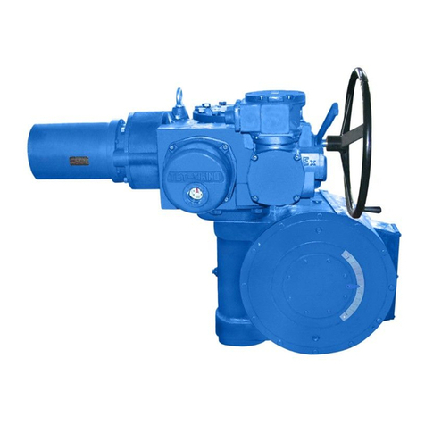
TIANJIN BAILI ERTONG MACHINERY XZA Series User manual
TIANJIN BAILI ERTONG MACHINERY
TIANJIN BAILI ERTONG MACHINERY SMC Series User manual
