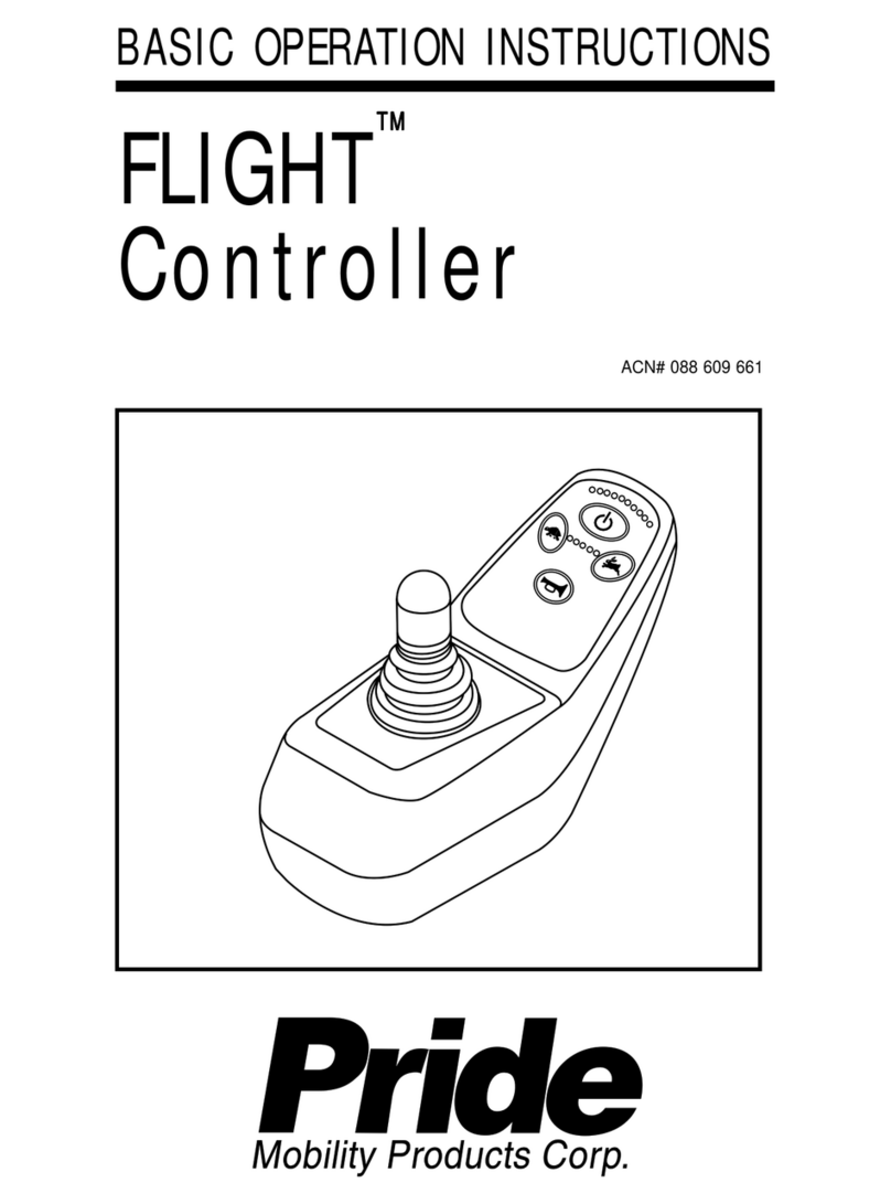
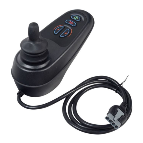
Pride Mobility Microdrive Controller INFMANU2581 User manual

ACN# 088 609 661
MicrodriveController
™
Synergy TRU-Balance
Po
BASIC OPERATION INSTRUCTIONS
Microdrive
Controller
ACN# 088 609 661
TMTM
TMTM
TM

2 BasicOperationInstructions
Microdrive Controller www.pridemobility.com
INFORMATION LABELING
Read and follow the information in the owner’s manual.
Avoid exposure to rain, snow, ice, salt, or standing water
whenever possible. Maintain and store in a clean and dry
condition.
Disposal and recycling - Contact your authorized Pride
Provider for information on proper disposal and recycling of
your Pride product and its packaging.
Copyright© 2006
PrideMobilityProductsCorporation
INFMANU2581/RevB/November 06
Thesymbols beloware usedthroughout thisowner's manualand onthe power
chairtoidentifywarningsandimportantinformation.Itisveryimportantforyouto
readthemandunderstandthemcompletely.
WARNING! Indicates a potentially hazardous condition/
situation. Failure to follow designated procedures can cause
either personal injury, component damage, or malfunction.
On the product, this icon is represented as a black symbol
on yellow triangle with black border.
MANDATORY! These actions should be performed as
specified. Failure to perform mandatory actions can cause
personal injury and/or equipment damage. On the product,
this icon is represented as a white symbol on a blue dot with
a white border.
PROHIBITED! These actions are prohibited. These actions
should not be performed at any time or in any circumstances.
Performing a prohibited action can cause injury to personnel
and/or damage to equipment. On the product, this icon is
represented as a black symbol with a red circle and a red
slash.

BasicOperationInstructions 3
www.pridemobility.com Microdrive Controller
TABLE OF CONTENTS
INTRODUCTION ................................................................................. 4
MICRODRIVE CONTROLLER........................................................ 6
PRECAUTIONARY GUIDELINES................................................. 6
OPERATING THE MICRODRIVE CONTROLLER ................ 10
JOYSTICK INTERFACE MODULE ............................................ 13
ACTUATOR ADJUSTMENT ......................................................... 15
DRIVE PROFILE SELECTION .................................................... 16
SPEED ADJUSTMENT.................................................................. 16
SLEEP MODE .................................................................................... 16
THERMAL ROLLBACK .................................................................. 16
ERROR CODES ................................................................................. 17
CARE AND MAINTENANCE ........................................................ 18
WARRANTY ........................................................................................ 18

4 BasicOperationInstructions
Microdrive Controller www.pridemobility.com
INTRODUCTION
WELCOMEto PrideMobility ProductsCorporation (Pride).The productyou
havepurchasedcombinesstate-of-the-artcomponents with safety, comfort, and
stylinginmind.Weareconfidentthatthedesignfeatureswillprovideyouwiththe
conveniencesyouexpectduringyourdailyactivities.Understandinghowtosafely
operateandcareforthisproductshouldbring you yearsoftroublefreeoperations
andservice.
Readand followallinstructions,warnings,andnotesinthismanualandallother
accompanying literature before attempting to operate this product for the first
time.Inaddition,yoursafetydependsuponyou,aswellasyourprovider,caretaker,
orhealthcareprofessionalinusinggoodjudgement.
Thismanualistobeusedinadditiontothepowerbaseowner’smanualthatcamewith
yourpowerchair.Ifthereisanyinformationinthismanualwhichyoudonotunderstand,
or if you require additional assistance for setup or operation, please contact your
authorizedPrideProvider.Failuretofollowtheinstructions,warnings,andnotes
inthismanualandthoselocatedonyourPrideproductcanresultinpersonal
injuryand/orproductdamageandwillvoidPride’sproductwarranty.
PURCHASER’SAGREEMENT
Byacceptingdeliveryofthisproduct,youpromisethat you will notchange,alter,
or modify this product or remove or render inoperable or unsafe any guards,
shields,orothersafetyfeaturesofthisproduct;fail,refuse,orneglecttoinstallany
retrofitkits fromtimeto timeprovided byPrideto enhanceor preserve thesafe
useofthis product.
INFORMATIONEXCHANGE
Wewant tohearyour questions,comments,and suggestions aboutthis manual.
We would also like to hear about the safety and reliability of your new Pride
product,andabouttheserviceyoureceivedfromyourauthorizedPrideProvider.
Pleasenotifyusofanychangeofaddress,sowecankeepyouapprisedofimportant
informationabout safety, newproducts, and newoptions that canincrease your
abilitytouse andenjoyyourPride product.

BasicOperationInstructions 5
www.pridemobility.com Microdrive Controller
NOTE: If you ever lose or misplace your product registration card or your
copy of this manual, contact us and we will be glad to send you a new one
immediately.
My authorized Pride Provider Is:
Name: _____________________________________________________
Address:____________________________________________________
PhoneNumber: ______________________________________________
PurchaseDate: _______________________________________________

6 BasicOperationInstructions
Microdrive Controller www.pridemobility.com
MICRODRIVECONTROLLER
TheMicrodriveControllerisafully-programmable,modularelectroniccontroller
systemthatallowsyoutooperateyourpowerchair. It is designedtoallowtheuser
tohavecomplete controloverchairmovement andspeed.
The controller has been pre-programmed to meet a typical user’s needs. The
programis set using either apersonal computer with software providedby the
controllermanufacturer orwith ahand-held programmer, also providedby the
controllermanufacturer.
WARNING! The controller program can affect speed,
acceleration, deceleration, dynamic stability, and braking.
If it is programmed incorrectly or outside of the safe limits
as determined by your healthcare professional, it can create
a dangerous situation. Only the power chair manufacturer,
an authorized representative of the manufacturer, or a trained
service technician should program the controller.
PRECAUTIONARYGUIDELINES
Before operating the Microdrive Controller, please read the following. These
guidelinesareprovided foryourbenefitand willaidyouin thesafeoperationof
thecontrolsystem.
!Turnoffthe power tothecontrollerwhentransferring to orfromyourpower
chair.
!Followalloftheproceduresandheedthewarningsasexplainedinyourpower
chairowner’smanual.
Failure to heed the above warnings can result in personal injury and/or
equipmentdamage.

BasicOperationInstructions 7
www.pridemobility.com Microdrive Controller
Electromagnetic and Radio Frequency Interference (EMI/RFI)
WARNING! Laboratory tests have shown that electromagnetic
and radio frequency waves can have an adverse affect on
the performance of electrically-powered mobility vehicles.
ElectromagneticandRadioFrequencyInterferencecancomefromsourcessuchas
cellularphones,mobiletwo-wayradios(suchaswalkie-talkies),radiostations,TV
stations,amateurradio(HAM)transmitters,wirelesscomputerlinks,microwavesig-
nals,pagingtransmitters,andmedium-rangemobiletransceiversusedbyemergency
vehicles.Insomecases,thesewavescancauseunintendedmovementordamageto
thecontrolsystem.Everyelectrically-poweredmobilityvehiclehasanimmunity(or
resistance)toEMI.Thehighertheimmunitylevel,thegreatertheprotectionagainst
EMI.Thisproducthasbeentestedandhaspassedatanimmunitylevelof20V/m.
WARNING! Be aware that cell phones, two-way radios,
laptops, and other types of radio transmitters may cause
unintended movement of your electrically-powered mobility
vehicle due to EMI. Exercise caution when using any of these
items while operating your mobility vehicle and avoid coming
into close proximity of radio and TV stations.
WARNING! The addition of accessories or components to
the electrically-powered mobility vehicle can increase the
susceptibility of the vehicle to EMI. Do not modify your power
chair in any way not authorized by Pride.
WARNING! The electrically-powered mobility vehicle itself
can disturb the performance of other electrical devices
located nearby, such as alarm systems.
NOTE: For further information on EMI/RFI, go to the Resource Center on
www.pridemobility.com. If unintended motion or brake release occurs, turn
yourcontroller offas soonasit issafe todoso. Contact Pride or your autho-
rized Pride Provider to report the incident.

8 BasicOperationInstructions
Microdrive Controller www.pridemobility.com
Microdrive Controller Features
Figure1 provides informationonthe Microdrivecomponentsand connections.
Usethis diagramto familiarize yourself with the function andlocation ofeach
componentbeforeusingtheMicrodriveController.
ThefollowingfunctionsareavailablewiththeMicrodriveController:
!JoystickControl
Thejoystick is usedto controlthedirection andspeed of thepower chair.
!ActuatorAdjustment
The user can control positioning of power accessory actuators with the
Microdrive.
!DriveProfileSelection
Theusercanselectoneoffiveavailabledriveprofiles,ifprogrammed.
!SpeedAdjustment
The user can increase or decrease the maximum speed of the power chair.
Thisadjustmentcanbe overriddenbytheJoystickInterface Module.
!SleepMode
Thisfeatureisdesignedtopreservebatterycharge,andcanbedisabledthrough
programming.
!ThermalRollback
Thisisasafetyfeaturedesignedtoprevent the power chairfromoverheating
andcausingdamage to themotorsorcontroller.

BasicOperationInstructions 9
www.pridemobility.com Microdrive Controller
Figure 1. Microdrive Components and Connections
BACK VIEW
Harness Connector Port
Used to connect the
Microdrive to the power base.
Joystick
A multi-functional tool used
to control speed, direction,
and actuator adjustment.
On/Off Switch
Press to power on or off the
power chair and controller.
Mode Switch
Used to select the various
functions available with the
Microdrive Controller.
Speed Adjustment Dial
Adjusts the maximum speed
of the power chair.
Horn Key
Activates a warning
horn.
Actuator Indicators
Four LEDs indicate
recline, tilt, power leg
rests, and elevating seat
actuator modes.
Battery Condition Meter
Indicates the approximate
amount of battery charge
using color-coded LEDs.
Profile/Speed
Indicator
Series of five colored
LEDs which display
the speed or profile
setting.
Battery Charger Port
Standard 3-pin XLR type
battery charger socket used
with off-board charging
systems.
Toggle switches to allow
or disallow various
functions via the
controller.
Joystick Interface
Module Controls
A 3.5 mm (1/8") jack
socket to allow connection
of external switches to
select the various
functions available
A 3.5 mm (1/8") jack
socket to allow connection
of external switches to
power on or off the power
chair and controller.

10 BasicOperationInstructions
Microdrive Controller www.pridemobility.com
Figure 2. Microdrive Controller and Joystick Interface Module
OPERATING THEMICRODRIVECONTROLLER
TheMicrodriveControllerisusedtooperateyourpowerchairandallofitscomponents.
TheMicrodrivecontrollerconsistsof:
1. joystick
2. displaypad
3. modeswitch
4. on/offswitch
5. speedadjustmentdial
6. joystickinterfacemodule

BasicOperationInstructions 11
www.pridemobility.com Microdrive Controller
Figure 3. Microdrive Display Pad
Joystick Control
The joystick controls the direction and speed of your power chair. When you
movethejoystick from theneutral(center) position, theelectromagneticbrakes
releaseandallowthepower chairtomove.Thefartheryoupushthejoystickfrom
itsneutralposition, thefasterthe power chairmoves.When youreleasethe joy-
stick and allow it to return to the neutral position, the electromagnetic brakes
engageand thepower chaircomes to a complete stop.
Display Pad
Thedisplaypadislocateddirectlyinfrontofthejoystick.Itcontainskeysthatyou
willuse to controlyour power chair.Seefigures 2and3.

12 BasicOperationInstructions
Microdrive Controller www.pridemobility.com
Horn Key
Thehornkey activates thehorn.
Battery Condition Meter
Thebatteryconditionmeterisa10-segmentilluminateddisplaythatindicatesthat
theMicrodrive ispowered on andalso givesthe statusof the batteries, the con-
troller,andthepowerchairelectricalsystem.
!!
!!
!Red,yellow,andgreenlightslit:Batteries charged;controllerandelectrical
systemOK.
!!
!!
!Redandyellowlightslit:Chargebatteriesifpossible;controllerandelectrical
systemOK.
!!
!!
!Red lights only lit or slow flash: Charge batteries as soon as possible;
controllerandelectricalsystemOK.
!!
!!
!Rapidflashoflights:Indicatesafaultinthecontrollerortheelectricalsystem.
See“Error Codes.”
!!
!!
!Ripplesideto side of lights:The joystick was not in the neutral position
whenthe controllerwas turnedon. Ifyou get“rippleside toside oflights,”
turnoffthecontroller,allowthe joystick to return to the neutral position,then
turnonthecontroller.
NOTE: If you have attempted to resolve the problem and still get “ripple
side to side of lights,” contact an authorized Pride Provider.
NOTE: When the batteries approach a discharged state, the first red light will
begin to slowly flash, reminding you the batteries need to be charged immedi-
ately!
Profile and Speed Indicator
Theprofileandspeed indicatorisa5-segmentilluminated displaythatindicates
speedsettingaswellas drive profile.
Actuator Indicator
Theactuator indicator is a 4-segmentilluminated displaythat indicates power
recline,power tilt,powerleg rest, andpowerelevating seatactuatormodes.

BasicOperationInstructions 13
www.pridemobility.com Microdrive Controller
JOYSTICK INTERFACE MODULE
Thejoystickinterfacemoduleprovidesameanstoenable or disable thehornkey,
modeswitch,on/offswitch,andspeedadjustmentdial.Seefigure4.
The joystick interface module consists of:
1. externalswitchjacks 5.power toggle
2. horntoggle 6. redelconnector port
3. speedtoggle 7.off-boardcharger/programmingsocket
4. mode toggle 8. speed adjustment dial
Figure 4. Joystick Interface Module

14 BasicOperationInstructions
Microdrive Controller www.pridemobility.com
NOTE: When a toggle switch is set to “J/S,”the joystick has control of a
particular function. When the toggle switch is set to “Local,”control of
this function is disabled at the joystick.
External Switch Jacks
The external switch jacks are used for an external control (e.g., buddy button,
singleswitch,etc.).Therearetwo externaljacksonthejoystickinterfacemodule:
modeandpower.Theswitchescanwork inconjunctionwithorinreplacementof
switchesonthejoystick.
Horn Toggle
Thehorntoggledisables the hornkeyonthecontroller.
SpeedToggle
Thespeedtoggle disables thespeedadjustmentdial on thecontroller.
ModeToggle
Themodetoggledisablesthe mode switchonthecontroller.
Power Toggle
Thepowertoggledisablesthe on/offswitchonthecontroller.
Redel Connector Port
Theredelconnector portisused forthepower module interface.
Off-board Charger/Programming Socket
Theoff-board charger/programming socket is usedfor off-boardcharger con-
nectionandcontrollerprogramming.Ifyouuseanoff-boardcharger,thecharger
current should not exceed 8 amps. Contact your authorized Pride Provider for
moreinformation.
WARNING! Only chargers with Neutrik NC3MX plugs should
be connected to the off-board charger/programming socket.
See your authorized Pride Provider for more information.
Failure to heed can result in personal injury and/or product
damage.

BasicOperationInstructions 15
www.pridemobility.com Microdrive Controller
ACTUATORADJUSTMENT
TheMicrodrive controller cancontrolfive poweraccessoryactuators using the
modeswitchandthe joystick.
To selectandadjust anactuator:
1. Usetheon/offswitchtopower onthechair and thecontroller.
2. Toactivatetheactuatoradjustmentmode,pressthemodeswitch downtwice.
3. Push the joystick to the right to cycle through the available actuators. The
actuatorindicatorwilldisplaywhichactuatorisactivated.Seefigure 5.
4. Whenthedesiredactuatorisselected,giveaforwardcommandtothejoystick
toadjustposition in onedirectionor give areversecommand to thejoystick
toadjustpositionin the oppositedirection.
5. Pressthe mode switchdown again toreturn tothedrive mode.
Figure 5. Actuator Indicators

16 BasicOperationInstructions
Microdrive Controller www.pridemobility.com
DRIVE PROFILE SELECTION
YourMicrodrivecontrollermaybe programmed formorethanonedrive profile
thatallowsthesystemto be customtailoredtoyourenvironment.
To select a profile setting:
1. Usetheon/offswitchtopower onthechair and thecontroller.
2. Pressthemode switch.
3. Movethe joystick leftorright toselectthe desired driveprofile. Each ofthe
LEDsintheprofile/speedindicatorindicatea separate profile.
NOTE: The system can be programmed with up to 5 different profiles.
SPEED ADJUSTMENT
TheMicrodrivecontroller providesaspeedadjustment dialtocontrolthe speed
ofthepower chair.
To change the speed:
1. Usetheon/offswitchtopower onthechair and thecontroller.
2. Toincreaseyourspeed, turn thespeedadjustment dialclockwise.
3. To decreaseyour speed, turnthespeed adjustmentdialcounterclockwise.
SLEEP MODE
TheMicrodrivecontrolleroffersasleepmodefeaturewhichwillshutoffthemain
powerifthe joystick remainsstationaryfora period offiveminutes.The battery
conditionmeterwillindicatesleepmodebyblinkingonceeveryfiveseconds.To
restorepowerandresume operationofthechair,flip the on/offswitchtwice.
THERMAL ROLLBACK
TheMicrodrivecontrollerisequippedwithathermalrollbackcircuitwhichmoni-
torsthetemperatureofthechair’smotorsandcontroller.Ifeitherexceeds122°F/
50°C,thecontroller reducesthemotor voltage by5 volts foreverydegree over.
This reduces the chair’s speed and allows a cool down period. Once the tem-
peraturereturnstoasafe level, the chairwillresumenormaloperation.

BasicOperationInstructions 17
www.pridemobility.com Microdrive Controller
ERRORCODES
Inadditionto indicating thecurrentstateof batterycharge,thebattery condition
metercanalsoindicatepossibleproblemswithyourpowerchair’selectricalsystem.
Ifanyofthebatteryconditionmeterlightsareflashingrapidly,thecontrollermaybe
indicatinganerror. Error codesaredisplayed as anumberof flashing lights.For
instance,ifthefirstlightisflashingrapidly,thebatteryvoltageisnearlydepleted.The
tablebelowidentifiestheindividualerrorcodes,probablecauses,andpossibleso-
lutions.Ifyoureceiveanyofthese errorcodesorifyouexperienceanyotherprob-
lems,contactyourauthorizedPrideProvider..
Fault Probable Cause(s) Possible Solution
Code
1 Flash The batteries need charging. Check the battery connections. If the
There is a bad connection battery connections are good, then
to the batteries. try charging the batteries.
2 Flashes There is a bad connection on Checkthe left motorconnectionsand
the left motor. wiring harnesses.
3 Flashes The left motor has a short to Contact your authorizedPride
a battery connection. Provider.
4 Flashes There is a bad connection on Check the right motor connections
the right motor. and wiring harnesses.
5 Flashes The right motor has a short to ContactyourauthorizedPride
a battery connection. Provider.
6 Flashes The charge inhibit has been Make sure that the battery charger
activated. is not connected to the power base.
7 Flashes There is a joystick fault. Makesure the joystickis in thecenter
position; power the unit off and then
on again.
8 Flashes There is a control system fault. Check power module and joystick
module connections and wiring.
9 Flashes The park brakes have a bad Check the left and right motor
connection. connections and wiring.
10 Flashes There is high battery voltage Measure the battery voltage. If it
in the system. exceeds 30VDC, replace the charger.

18 BasicOperationInstructions
Microdrive Controller www.pridemobility.com
CAREAND MAINTENANCE
Refer to your power chair owner’s manual for proper cleaning and disposal
instructions.
WARRANTY
For two (2) years from the date of purchase, Pride will repair or replace at our
optiontotheoriginalpurchaser,freeofcharge,thecontrolleroranyofitscomponents
founduponexaminationbyan authorized representativeofPridetobedefective
inmaterialand/orworkmanship.

BasicOperationInstructions 19
www.pridemobility.com Microdrive Controller
NOTES

*INFMANU2581*
www.pridemobility.com www.prideservice.com www.quantumrehab.com
Pride Mobility Products Corporation
182 Susquehanna Avenue
Exeter, PA 18643-2694
USA
Pride Mobility Products Company
380 Vansickle Road Unit 350
St. Catharines, Ontario L2R 6P7
Canada
Pride Mobility Products Ltd.
Unit 106, Heyford Park Camp Road
Upper Heyford, Oxfordshire OX25 5HA
Pride Mobility Products Australia Pty.Ltd.
21 Healey Road
Dandenong, 3175
Victoria, Australia
Pride Mobility Products Italia S.r.l.
Via del Progresso - ang. Via del Lavoro
Loc. Prato della Corte
00065-Fiano Romano (RM)
Pride Mobility Products Europe B.V.
Tijnmuiden 28
1046 AL Amsterdam
The Netherlands
This manual suits for next models
1
Table of contents
Other Pride Mobility Controllers manuals