manuals.online logo
Brands
  1. Home
  2. •
  3. Brands
  4. •
  5. Primera
  6. •
  7. Lock
  8. •
  9. Primera SAFEHINGE JUNIOR-RHINO PR-6308-BR-LL User manual

Primera SAFEHINGE JUNIOR-RHINO PR-6308-BR-LL User manual

Locking for Slave Leaf Doors
(PR-6308-BR-LL)
a) 76mm (3”) Deadbolt C/W Face Plate & Strike Plate
b) 4 x 1¼” No 8 Lock and Strike Plate Fixing Screws
c) 70mm x 70mm Escutcheon Plate Assembly
d) 4 x 5/8” x No 6 Escutcheon Plate Fixing Screws
e) Life-Line Escutcheon C/W 8mm Spindle & Grub Screw
f) 2 x M4 x 16 Escutcheon Fixing Machine Screws
Contents List
Junior-Rhino
Junior-Rhino
LL
™
c
All rights reserved © 2015 Primera Ltd
d
b
f
e
a
(Key Not Included In Kit)
Part No. PR-7320-LLZ-BK
Important Note: Primera products are protected by Intellectual Property Rights including UK and Community Unregistered Design Rights,
UK and Community Registered Designs and UK patents and patent applicaons.
44
50
135



18mm
D)Installing lock in the foot of the door
Note: Before begining the installaon of the lock in the foot
of the door it is important that the followers on the top
and the boom lock are in alignment.
1) Remove the door before fing the lock.
2) Mark the installaon posion on the foot of the door.
Diagram 12.
3) Carefully prepare a morce pocket 85mm x 85mm. Take
care to ensure the morce is posioned centrally in the
door shown at Diagram 13
4) Ensure all debris is removed and check the lock sits
comfortably in the hole all the way to the back of the
fore-end without force.
5) With the bolt extended and the square face plate in
posion, mark a pencil line around the face-plate as
shown at Diagram 14. Remove lock and set aside.
6) Using a chisel, remove 4mm of mber inside the pencil
lines as shown Diagram 15 to allow the front of the face
plate to sit flush with the surface of the mber when
lock is in posion.
E) Fing the Escutcheon Assembly
1) Follow installaon procedure B illustrated overleaf.
2) Re-hang the door before fing the strike plate.
F) Fing the Flat Strike Plate
1) The procedure C overleaf can be used as a general
guide when fing a strike plate to mber floor.
12
14
15
13
For further details please contact
Primera Limited, Unit 8 Bankfield House, 250 Bristol Avenue, Blackpool, FY2 0JF
t 0330 058 0988 f 01253 508652
e[email protected] w www.safehinge.com
SOP094 Revision (1)
a) Drill
b) 18mm Auger, Forstner or Flat Steel Bit
c) 6mm HSS Drill Bit
d) 2.0mm HSS Pilot Drill Bit
e) 22mm Flat Bit
f) 13mm Flat Bit
g) Chisel 1”
h) Chisel ½”
i) Hex Socket Screwdriver
j) T15 Pin Torx Bit
k) T20 Pin Torx Bit
l) Hammer
m) Tape Measure
n) Pencil
o) 1.5mm Allen Key
q) Life-Line Key - Pn. PR-7320-LLZ-BK
(not included in the kit )
A) Installing lock in the head of the door
1) Mark the installaon posion on the top edge of the door.
Diagram 1.
2) Carefully prepare a morce pocket 85mm x 85mm x
18mm. Take care to ensure the morce is posioned
centrally in the door as shown at Diagram 2
3) Ensure all debris is removed and check the lock sits
comfortably in the hole all the way to the back of the
fore-end without force.
4) With the bolt extended and the square face plate in
posion, mark a pencil line around the face-plate as shown
at Diagram 3. Remove lock and set aside.
5) Using a chisel, remove 4mm of mber inside the pencil line
as shown at Diagram 4, to allow the front of the face plate
to sit flush with the surface of the mber when lock is in
posion.
B) Fing the Escutcheon Assembly
1) Mark a pencil point 57mm from the top of the door and
110mm from the edge of the door as shown at Diagram 5
Using a 22mm flat bit, drill a hole to receive the spindle and
key-drive housing. (Not a through hole - drill one side only).
Re-fit the lock and check to ensure the hole is perfectly
aligned centrally to the square follower.
2) Offer the escutcheon assembly up to the door and mark
the posion of the protruding machine screws. Drill two
appropriate holes (6mm) that will enable the plate to sit flat
against the surface of the door as shown at Diagram 6.
3) Using the spindle formula in figure (7) cut the spindle to the
required length, taking care not to trim the end with the through
hole. Align the spindle in the escutcheon assembly and secure
using grub screw supplied. Ensure that the grub screw is fully
ghtened using 1.5mm Allen Key as shown at Diagram 8.
4) With the key indent at the 12.00 o’clock posion and with the bolt
withdrawn, offer the escutcheon assembly on to the door aligning
the spindle in to the follower on the lock. Test the key to ensure lock
works properly.
5) Using the 2mm drill, carefully drill four pilot holes for the plate
fixings as shown at Diagram 9.
6) Fasten the Escutcheon Plate to the door using 4 x 5/8” No 6 screws.
The plate must be sat firmly back to the surface of the door to
prevent any potenal ligature risk.
7) Using the key, operate the lock again to ensure the bolt can be
thrown and withdrawn easily.
8) Using the lock fore-end as a guide, pilot drill two holes and secure
lock and faceplate in posion using 2 x 1”¼ No. 8 screws as shown
at Diagram 9.
Door Thickness ÷ 2 + 7mm = Spindle Lgth
Example where door is 44mm
44mm ÷ 2 + 7mm = Spindle Lgth of 29mm
Installaon Procedure
Spindle Formula



44
18
85
85
50
135
57
110
= Mark with pencil = Drill Pilot Hole
2
4
6
5
1



18mm
22mm
6mm
3

13mm
25
95
Dim A
1.5
C) Fing the Flat Strike Plate
1) With the bolt extended, carefully close the door against the frame
and mark a pencil line on either side as illustrated at 10. Then, using
a Square transfer the lines across the rebate to mark the cut out for
the bolt.
2) With the bolt withdrawn, close the door and inspect the door
alignment in the frame from the inside taking note of any gap or twist.
Then with the door open and bolt extended, measure from the back
edge of the door to the back of the bolt as shown at dimension ‘A’
3) Mark dimension ‘A’ in the frame rebate as shown at Diagram 11
allowing for any gap or twist idenfied at point 2.
4) Using the markings as a guide, squarely align the strike plate in the
frame rebate and draw a pencil line around the rectangular hole for
the bolt cut out.
5) Using a 13mm flat bit, drill a hole 17mm deep to remove the bulk of
the mber cut out. Aerwards, chisel the residual mber in the
corners away leaving a neat rectangular hole.
6) Close the door and throw the bolt to check the alignment is correct
before fing the strike.
7) Carefully align the strike plate over the bolt cut out and mark a pencil
line around the plate.
8) Using a chisel, let the strike in to the rebate so that it sits flush with
the surface of the mber.
9) Using a 2mm bit, drill four pilot holes for the strike plate fixings and
secure the strike into posion using the 4 x 1 ¼” No 8 screws
supplied.
10) The above technique can be used as a general guide when fing a
strike plate to mber floor.
See overleaf for installing the lock in the foot of the door.
2 mm Pilot


Dim A
Tools Required
8
9
10
11
7
2 mm Pilot
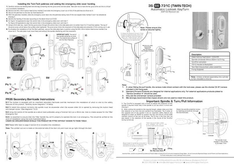
Other Primera Lock manuals

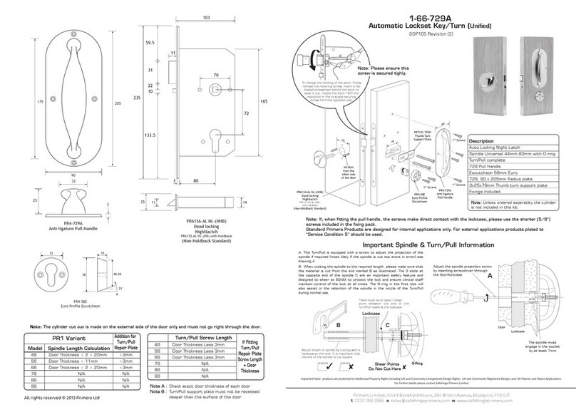
Primera 1-64-729A Assembly instructions

Primera

Primera 1-64-729A Assembly instructions

Primera SAFEHINGE RHINO-LOCK PR-6304-RB-RK-LL User manual

Primera

Primera SAFEHINGE RHINO-LOCK PR-6304-RB-RK-LL User manual

Primera 3S-76 -729A TWIN-TECH User manual

Primera

Primera 3S-76 -729A TWIN-TECH User manual

Primera 3S-66-731C User manual

Primera

Primera 3S-66-731C User manual

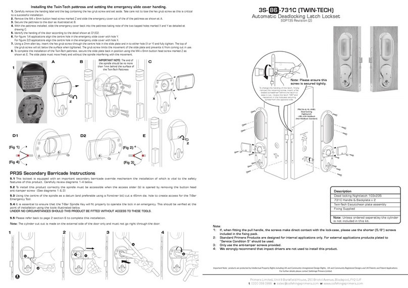
Primera TWIN-TECH 3S-86-731C Assembly instructions

Primera

Primera TWIN-TECH 3S-86-731C Assembly instructions

Primera 1-86-729C Assembly instructions

Primera

Primera 1-86-729C Assembly instructions

Primera 3S-86-729A TWIN-TECH User manual

Primera

Primera 3S-86-729A TWIN-TECH User manual

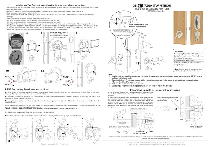
Primera 3S-64-729A TWIN-TECH User manual

Primera

Primera 3S-64-729A TWIN-TECH User manual

Primera 1-66-729A Assembly instructions

Primera

Primera 1-66-729A Assembly instructions

Popular Lock manuals by other brands

Manhattan 440271 instructions

Manhattan

Manhattan 440271 instructions

Kaba Group Ilco 770 Rework Installation Sheet

Kaba Group

Kaba Group Ilco 770 Rework Installation Sheet

Securefast SBL339/SP installation instructions

Securefast

Securefast SBL339/SP installation instructions

GLOBAL LINK Ultra ES Pro Smart Lock User instructions

GLOBAL LINK

GLOBAL LINK Ultra ES Pro Smart Lock User instructions

Noark MIT26 installation instructions

Noark

Noark MIT26 installation instructions

american lock A700 Assembly/disassembly manual

american lock

american lock A700 Assembly/disassembly manual

Schlage AD-300 user guide

Schlage

Schlage AD-300 user guide

Sylvan SL38E user manual

Sylvan

Sylvan SL38E user manual

Alarm Lock PM1200 Wiring instruction

Alarm Lock

Alarm Lock PM1200 Wiring instruction

INOX 8000 Series quick start guide

INOX

INOX 8000 Series quick start guide

Promet PS300/E31 user manual

Promet

Promet PS300/E31 user manual

ACSI HAGER 45CE instructions

ACSI

ACSI HAGER 45CE instructions

Mottura 35 Series Assembly instructions

Mottura

Mottura 35 Series Assembly instructions

Schlage Door Lock Brochure & specs

Schlage

Schlage Door Lock Brochure & specs

Häfele DL7900 user manual

Häfele

Häfele DL7900 user manual

Assa Abloy Sargent 8200 installation instructions

Assa Abloy

Assa Abloy Sargent 8200 installation instructions

CISA MyEVO installation instructions

CISA

CISA MyEVO installation instructions

AMSEC BSL-0601A-W Operating and installation instructions

AMSEC

AMSEC BSL-0601A-W Operating and installation instructions

manuals.online logo
manuals.online logoBrands
  • About & Mission
  • Contact us
  • Privacy Policy
  • Terms and Conditions

Copyright 2025 Manuals.Online. All Rights Reserved.