PrimeWeld CT520D User manual

MODEL:CT520D
IGBT INVERTER PLASMA CUTTER
OWNER`S
MANUAL
Need Help
Please Call
856-537-4368
www.primeweld.com

1
CONTENTS
EC DECLARATION OF CONFORMITY
We hereby declare that our machines for industrial and
professional use as stated below.
Model: CT520D.
Conforms with EMC Directives:
73/23/EEC and 89/336/EEC
European Standard: EN/IEC60974
Please read and understand this instruction manual carefully
before the installation and operation of this equipment.
The contents of this manual may be revised without prior notice
and without obligation.
This instruction manual is issued on 20 July 2020.
SAFETY ......................................................................................... 2
PARAMETER ................................................................................. 7
LAYOUT ......................................................................................... 8
OPERATION .................................................................................. 16
ACCESSORIES ............................................................................. 30
TROUBLE SHOOTTING............................................................... 32

2
SAFETY
WARNING
Welding and cutting is dangerous to the operator, people in or near the working
and surrounding areas, if the equipment is not operated correctly. Therefore the
performance of welding/cutting must only be under the strict and comprehensive
observance of all relevant safety regulations.
Symbol Description
Electric Shock: Maybe fetal
Avoid all contact with live components of the welding circuit, Electrodes and Wires
with bare bands. Wear dry gloves before start welding task.
Wires with bare bands Keep operator insurance from welding metal and welding pieces.
Smoke and gas generated while welding or cutting
Harmful to health of people
Keep head distance away from gas.
Avoid breathing the smoke and gas of welding or cutting.
Keep the working area in good ventilation.
Fire Hazard
Welding sparks, Power cable leakage both can cause the re.
Please do not welding in inammable, it’s can cause explode.
Sparks may cause re, Remove ammable material from the work place.
Keep re extinguisher nearby and have a trained re person ready to use it.
ARC light-emission: Harmful to the eyes & skin of people
Wear a welding helmet, Anti-radiation glass and work clothes while the
welding Operation is performed.
Keep working area in ventilation.
CYLINDER may explode if damaged.
Always keep cylinders in an upright position securely chained to an
Undercarriage or xed support.
Never allow the electrode, electrode holder or any other electrically “hot”
parts to touch a cylinder.
Keep your face and head away from the cylinder valve outlet when it to
be opening.
Engine fan can hurt the hands
Do not put your hands near the engine fan.
Do not attempt to override the governor or idler by pushing on the throttle
Control rods while the engine is running.
ELECTRIC SHOCK can kill.
Insulate yourself from work and ground using dry insulation. Make certain
the insulation is large enough to cover your full area of physical.
Ground the work or metal to be welded to a good electrical ground.
Never dip the electrode in water for cooling.
Turn o input power using the disconnect switch at the fuse box before
working on the equipment.
Install equipment in accordance with electric standard code.

3
SAFETY
CAUTION
1.Working Environment.
1.1 The environment in which this welding equipment is installed must be free of
grinding dust, corrosive chemicals, ammable gas or materials etc, and at no
more than maximum of 80% humidity.
1.2 When using the machine outdoors protect the machine from direct sun light,
rain water and snow etc;the temperature of working environment should be
maintained within -14°F to +104°F.
1.3 Keep this equipment distant from the wall.
1.4 Ensure the working environment is well ventilated.
2.Safety Tips.
2.1 Ventilation
This equipment is small-sized, compact in structure, and of excellent
performance in amperage output.The fan is used to dissipate heat generated
by this equipment during the welding operation. Important: Maintain good
ventilation of the louvers of this equipment. The minimum distance betweenthis
equipment and any other objects in or near the working area should be 1ft.
Good ventilation is of critical importance for the normal performance and
service life of this equipment.
2.2 Thermal Overload protection.
Should the machine be used to an excessive level, or in high temperature
environment, poorly ventilated area or if the fan malfunctions the Thermal
Overload Switch will be activated and the machine will cease to operate. Under
this circumstance, leave the machine switched on to keep the built-in fan
working to bring down the temperature inside the equipment. The machine will
be ready for use again when the internal temperature reaches safe level.
2.3 Over-Voltage Supply
Regarding the power supply voltage range of the machine, please refer to“Main
parameter”table. This equipment is of automatic voltage compensation, which
enables the maintaining of the voltage range within the given range. In case
that the voltage of input power supply amperage exceeds the stipulated value,
it is possible to cause damage to the components of this equipment. Please
ensure your primary power supply is correct.
2.4 Do not come into contact with the output terminals while the machine is in
operation. An electric shock may possibly occur.

4
SAFETY
Maintenance
Exposure to extremely dusty, damp, or corrosive air is damaging to the welding
machine. In order to prevent any possible failure or fault of this welding
equipment, clean the dust at regular intervals with clean and dry compressed air
of required pressure.
Please note that: lack of maintenance can result in the cancellation of the
guarantee; the guarantee of this welding equipment will be void if the machine
has been modied, attempt to take apart the machine or open the factory-made
sealing of the machine without the consent of an authorized representative of the
manufacturer.
Trouble shooting
Caution: Only qualied technicians are authorized to undertake the repair of this
Plasma cutter equipment. For your safety and to avoid Electrical Shock, please
observe all safety notes and precautions detailed in this manual.
Note:
• Our equipment as described in this manual conforms to all applicable rules and
regulations of the ‘Low Voltage Directive’ (European Council Directive 73/23/EEC)
as set out and amended by Council Directive 93/68/EEC) and to the National
legislation for the enforcement of this Directive.
• Our equipment as described in this manual conforms to all applicable rules and
regulations of the European Council Directive 89/336/EEC, (EMC Directive)
and to the National legislation for he enforcement of this Directive.
Aip plasma cutting technology
Plasma cutters work by passing an electric arc through a gas that is passing
through a constricted opening. The gas can be air, nitrogen, argon, oxygen. etc.
The electric arc elevates the temperature of the gas to the point that it enters a
4th state of matter. We all are familiar with the rst three: i.e.,Solid, liquid, and gas.
Scientists call this additional state plasma. As the metal being cut is part of the
circuit, the electrical conductivity of the plasma causes the arc to transfer to the
work. The restricted opening (nozzle) the gas passes through causes it to
squeeze by at a high speed, like air passing through a venturi in a carburettor.
This high speed gas cuts through the molten metal.
Plasma cutting was invented as the result of trying to develop a better welding
process. Many improvements then led to making this technology what it is today.
Plasma cutters provide the best combination of accuracy, speed, and aord ability
for producing a variety of at metal shapes. They can cut much ner, and faster
than oxy-acetylene torches.

5
SAFETY
How a plasma cutter works
Basic plasma cutters use electricity to superheat air into plasma (the 4th state of
matter), which is then blown through the metal to be cut. Plasma cutters require
a compressed air supply and AC power to operate.
Operation
1. When the trigger is squeezed, DC current ows through the torch lead into the
nozzle.
2. Next, compressed air ows through the torch head, through the air diuser that
spirals the air ow around the electrode and through the hole of the cutting
nozzle.
3. A xed gap is established between the electrode and the nozzle. (The power
supply increases voltage in order to maintain a constant current through the
joint.) Electrons arc across the gap, ionizing and super heating the air creating a
plasma stream.
4. Finally, the regulated DC current is switched so that it no longer ows to the
nozzle but instead ows from the electrode to the work piece. Current and airow
continue until cutting is stopped.
Shield Cup
Nozzle
Electrode
Plasma Stream
Steel
Notes:
The nozzle and electrode require periodic replacement. The electrode has an insert
of tough high conductive material such as hafnium and cerium. This insert erodes
with use, also the nozzle orice will erode with use.
Quality of the air used is paramount to longer life of electrodes and nozzles, in
short clean dry air gives longer parts life, the cleaner and dryer the better. We
recommend use of a Plasma Air Filter.

6
SAFETY
What kinds of materials can the plasma cut?
Virtually any metal can be plasma cut including steel, stainless steel, aluminium,
brass, copper, etc. Any thickness from 30 gauge through 13/16" can be cut,
depending on the power of the plasma cutter used.
How Does Plasma Cutting Compare to Oxy-fuel (gas) cutting?
Plasma cutting can be performed on any type of conductive metal - mild steel,
aluminium and stainless are some examples. With mild steel, operators will
experience faster, thicker cuts than with alloys. Oxy-fuel cuts by burning, or
oxidizing the metal it is severing. It is therefore limited to steel and other ferrous
metals which support the oxidizing process. Metals like aluminium and stainless
steel form an oxide that inhibits further oxidization, making conventional oxy-fuel
cutting impossible. Plasma cutting however does not rely on oxidation to work
and thus it can cut aluminium, stainless and any other conductive material. While
dierent gasses can be used for plasma cutting, most people today use
compressed air for the plasma gas. In most shops, compressed air is readily
available, and thus plasma does not require fuel gas and compressed oxygen for
operation. Plasma cutting is typically easier for the novice to master, and on
thinner materials, plasma cutting is much faster than oxy-fuel cutting. However,
for heavy sections of steel (1" and greater), oxy-fuel is still preferred since
oxy-fuel is typically faster and, for heavier plate applications high powered
plasma machines are required for plasma cutting applications
What are the limitations to Plasma Cutting?
Where is Oxyfuel preferred?
The plasma cutting machines are typically more expensive than oxy/acetylene.
Also, oxy/acetylene does not require access to electrical power or compressed
air which may make it a more convenient method for some users. Oxyfuel can
generally cut thicker sections (>63/64 inch) of steel more quickly than plasma.

7
PARAMETER
INPUT/OUTPUT SPECIFICATIONS
IGBT Inverter Type: IGBT
Voltage/phase: Dual Voltage 120/240 1 Phase
TIG output type: DC only
TIG Start Type: High Frequency Only
Pulse: No
Plasma Cutter Arc Start Type: High Frequency
PilotArc: No
OK-to-Cut Indicator/Low Air pressure safety: No
OCV:
▪TIG: 70 V
▪Stick: 70 V
▪Plasma: 220V
Max Inrush ( I1MAX ) Amps: ▪@ 110V: 31A
▪@ 220V: 27A
Maximum Rated (I1EFF ) Input Amps: ▪@110V: 19A
▪@220V: 17A
TIG Output Amps/Volts @ Rated Duty Cycle:
120V:
▪ 120A/14.8V @ 35% Duty Cycle
▪ 93A/13.7V @ 60% Duty Cycle
▪ 72A/12/9V @ 100% Duty Cycle
240V:
▪ 200A/18V @ 35% Duty Cycle
▪ 160A/16.4V @ 60% Duty Cycle
▪ 130A/15.2V @ 100% Duty Cycle
Stick Output Amps/Volts @ Rated Duty Cycle:
F120V:
▪ 120A/24.8V @ 35% Duty Cycle
▪ 93A/23.7V @ 60% Duty Cycle
▪ 72A/22.9V @ 100% Duty Cycle
240V:
▪ 160A/26.4V @ 35% Duty Cycle
▪ 130A/25.2V @ 60% Duty Cycle
▪ 100A/24V @ 100% Duty Cycle
Plasma Output Amps/Volts @ Rated Duty Cycle:
120V:
▪ 27A/90.8V @ 60% Duty Cycle
▪ 21A/88.4V @ 100% Duty Cycle
240V:
▪ 50A/100V @ 35% Duty Cycle
▪ 40A/96V @ 60% Duty Cycle
▪ 30A/92V @ 100% Duty Cycle
TIG DC Amp/Volt Range: ▪120V: 10A-120A, 10.4V-14.8V
▪240V: 10A-200A, 10.4V-18V
Stick Amp/Volt Range: ▪120V: 10A-120A, 20.4V-24.8V
▪240V: 10A-160A, 20.4V-26.4V
Plasma Amp/Volt Range: ▪120V: 10A-27A, 84V-94V
▪240V: 10A-50A, 84V-100V
Preow time: Fixed
Post Flow Time: Fixed
OverCurrent Protection: Yes

8
LAYOUT
Duty Cycle Protection: Yes
Air Pressure OK Safety Indicator: No
Stick Arc Force Control: Auto-Adaptive
Torch Type: t AG-60 High Frequency
Recommended Cutting Air Pressure: 55-60 psi
Front & rear panel layout
Front Panel Rear Panel
91
2
3
4
5
10
11
13
12
6
7
8
14
16
17
18
20
19
15
9
LAYOUT
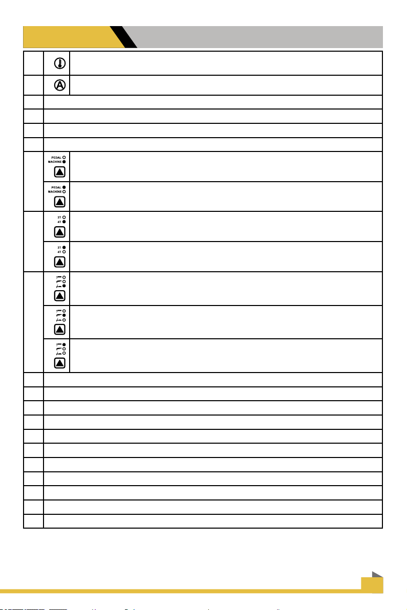
1Overheating indicator, It illuminates when the working temperature of the IGBT is
overly high. Meanwhile,The machine stop working.
2It is current indicator, Lighting when machine power on
3 LED Current Display.
4 Amperage Control Knob.
5 Time adjument for post air
6Air Pressure Gauge.Suggest Air Range: 45-70PSI
7
Machine indicator, Current knob can use in this selection, can not use pedal.
Pedal: current knob on machine can not be used in this selection, Can use the
pedal adjust the current
8
4T is selected press and release trigger Arc starts, press and release trigger Arc
stops.
2T is selected press trigger Arc starts, release trigger Arc stops.
9
TIG function please select it before using machine
Cutting function please select it before using machine
Stick function please select it before using machine
10 Stick connector
11 TIG and Cutting torch connector
12 Switch connector for TIG and Cutting torch
13 Earth clamp connector
14 Air regulator
15 Power switch
16 Quick air connector
17 Power cable Input Voltage 110/220v, Voltage Automatic Identication, no need hand switch
18 Argon Gas in
19 Air in
20 To Air Meter

10
LAYOUT
Set up procedure for plasma cutting machine
1. Connect the AG60/AG60P Plasma Torch to the machine. Insert the torch connection into the
torch.Connection receptacle at the front of the machine and screw up hand tight. Caution: Be
careful not to bend the pins located inside the torch connector.
2. Connect the earth lead to the output terminal of the machine and tighten.
3. Connect the air supply to the air connection located at the rear of the machine. Turn on the air
supply.
4. Connect the machine to the correct power supply and switch on the machine using the on/o
switch located at the rear of the machine.
5. Select 2T / 4T operation
Operating procedure using the 2T / 4T Function with AG60/AG60P torch. Set torch operation
2T / 4T.
• When 2T operation is selected press trigger Arc starts, release trigger Arc stops.
• When 4T operation is selected press and release trigger Arc starts, press and release trigger
Arc stops.
6. Set amperage dial.
How to begin use this machine
Before use this machine, you need to read the blow information carefully, Put the
accessories ready before operate this unit.
Connect the earth
lead to the output
terminal Of the
machine and tight
Connect the Plasma cutting torch to the
machine set the torch connection into
the torch connection
Receptacle at the front of the machine
and Screw up hand tight.

11
LAYOUT
CONNECTION
Switch
connector for TIG
and Cutting torch
Stick
connector
TIG and Cutting
torch connector Earth clamp
connector
Before use pedal, please switch function "Machine"to "Pedal " please connect torch and
ground clamp well, leave torch switch free(do not plug it to TIG torch switch port), Connect
foot pedal to panel of machine.
5 PIN CONNECTOR FOR FOOT PEDAL
1
2
5
3
4
Ground
Torch Switch
Torch Switch
Power
Setting
Amps
VR in the foot pedal
FOOT PEDAL
12
LAYOUT
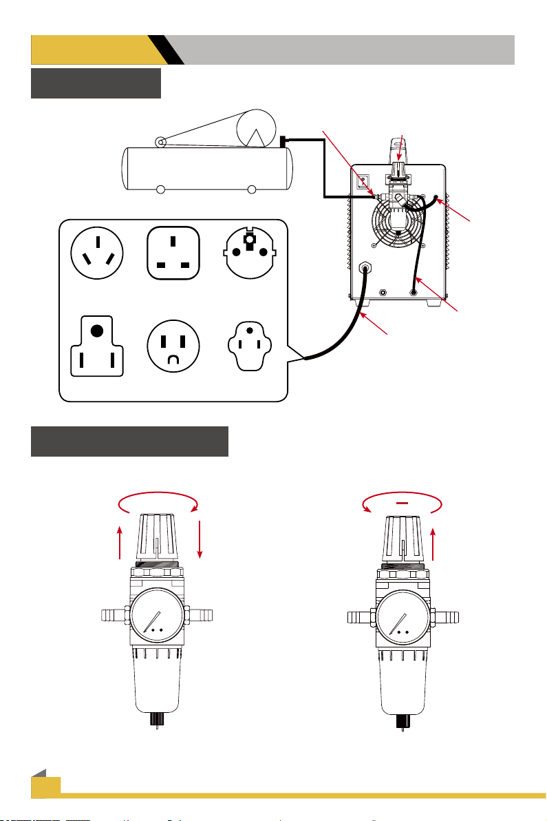
Connection
Air Compressor
AU UK EURO
USA 110V USA 220V
Air
regulator
Air input
Power cable
Air hose
to air
meter
Air hose to
torch
How to use air regulator
Anti-Clockwise
Reduce air pressure
+
Pull up Pull down
Clockwise increase
air pressure
Air Pressure range: 40-70 PSI

13
LAYOUT
Function & Install instruction
HOW TO USE MMA(Stick)
Select MMA mode, Stick holder connect to
left socket, same time connect earth clamp
to the right socket.
HOW TO USE CUT
Before start use cutting function, need to
select cut mode, then connect torch and
switch and pilot arc wire also earth clamp
to panel of machine. start cutting after all
connectting.
HOW TO USE TIG
Select TIG mode, connect torch, switch and
earth clamp to panel of machine. start TIG
welding after nish all connectting.
1. For connect stick holder
2. GAS/AIR OUTLET
3. PEAL/ Torch switch
4. For connect earth clamp
12 3 4

14
LAYOUT
How to connect wire for TIG
welding.
1. Connect the TIG torch & switch to
panel of machine
2. connect the plug of earth clamp to
the machine socket.
How to connect wire for
cutting function
1. connect the plasma torch & switch
to socket of panel, ( also need to
connect the pilot arc wire if machine
with pilot arc function )
2. connect the earth clamp to socket
on panel of machine
How to connect wire for
stick welding
1. connect the plug on wire of stick
holder to panel of machine ( there is
symbol mark on machine )
2. connect the plug on wire of earth
clamp to panel of machine.

15
LAYOUT
Cutting Thickness Chart
Need to adjust the current and air pressure properly under metal thickness to get best cutting
surface
1
CT520 (220V) 20Amps 30Amps 40Amps 50Amps
Thickness (mm) 4mm 6mm 10mm 14mm
Air Pressure (psi) 40psi 50psi 60psi 70psi
Tip size φ0.8-φ0.9 φ0.8-φ0.9 φ0.9-φ1.0 φ0.9-φ1.0
2
CT520 (110V) 25Amps 35Amps
Thickness (mm) 4mm 6mm
Air Pressure (psi) 40psi 50psi
Tip size φ0.8-φ0.9 φ0.8-φ0.9
Accessories
Following accessories come with machine
1. machine x 1
2. plasma cutting torch x 1
3. earth clamp with cable x 1
4. air hose x 1
5. cutting torch tip x 2
6. cutting torch electrode x 2
7. Air regulator x 1
8. Power plug wire adaptor x 1
9. TIG torch * 1
10. Arc holder with cable *1
16
LAYOUTOPERATION
1.place and hold the torch vertical At the
edge of the plate.
2. Pull the trigger to energise the pilot arc.
The cutting arc will start when the nozzle
is moved closer to the edge of the work
piece. When the cutting arc has cut
through the edge of the plate start moving
evenly in the direction you wish to cut.
3. Correct amperage and travel speed arc
importand and relevant to material
thickness and are correct when sparks
are exiting from the work piece. if sparks
are spraying up from the work piece there
is insucient amps selected or the travel
speed is too fast.
4. To nish the cutting release the torch
switch. The air ow will continue for 20
seconds to cool the torch head.
Cut Quality
A clean cut depend on several factors: Poor quality cut
● amperage
● travel speed
● tip height & position
● tip and electrode quality Good quality cut
● air pressure and quality
● technique
The best quality cut will be produced when all these variables are set correctly
for the material thickness and type of material being cut.

17
LAYOUTOPERATION
Amperage
Standard rule of thumb is the thicker the material the more amperage required.On thick material,
set the machine to full output and vary your travel speed.On thinner material, you need to turn
down the amperage and change to a lower-amperage tip to maintain a narrow kerf. The kerf is the
width of the cut material that is removed during cutting.
Speed
Amperage and speed are critical to producing a good quality cut. The faster you move (especially
on aluminium), the cleaner your cut will be. To determine if you're going too fast or too slow, visually
follow the arc that is coming from the bottom of the cut. The arc should exit the material at a slight
angle away from the direction of travel. If it's going straight down, that means you're going too slow,
and you'll have an unnecessary buildup of dross or slag. If you go too fast, it will start spraying back
onto the surface of the material without cutting all the way through. Because the arc trails at an
angle, at the end of a cut, slow your cutting speed and angle the torch in to cut through the last bit
of metal.
Direction
It is easier to pull the torch towards you than push it. The plasma stream swirls as it exits the tip,
biting one side and nishing o on the other leaving a bevelled edge and a straight edge. The
bevel cut eect is more noticeable on thicker material and needs to taken into consideration before
starting your cut as you want the straight side of the cut to be on the nished piece you keep.
Torch tip height & position
The distance and postion of the plasma torch cutting tip has an aect on the quality of the cut and
the extent of the bevel of the cut. The easiest way to reduce bevel is by cutting at the proper speed
and height for the material and amperage that is being cut.
Correct torch height and
Square to the material
Minimum bevel & equal bevel
Longest consumable life
Torch angled to the material
unequal bevel, one side may
be excessively beveled.

18
LAYOUTOPERATION
Torch height too high
excessive bevel, plasma
Stream may not cut all the
way through the material
Torch height too low
Reverse bevel. Tip may
contact the work piece and
short out or damage the tip.
Tip size and condition
The tip orices focus the plasma stream to the work piece. It is important to use the correct size tip
for the amperage being used,for example a tip with a 3/64" orice is good for 0-40 amps whereas a
1/16" orice is better for 40-80 amps.
The low-amp tip has a smaller orice which maintains a narrow plasma stream at lower settings for
use on thin-gauge material. Using a 25 amp tip at an 60 amp setting will blow out and distort the tip
orice and require replacement. Conversely, using an 80-amp tip on the lower settings will not allow
you to focus the plasma stream as well and creates a wide kerf.The condi tion of the tip orice is
critical to the quality of the cut result, a worn or damaged tip orice will produce a distorted plasma
stream resulting in a poor cut quality.
Electrode condition
A xed gap is established between the electrode and the inside of the cutting tip.
Electrons arc across the gap, ionizing and super heating the air creating the plasma stream. The
electrode contains an insert in the end made of a highly conductive material called hafnium. This
insert erodes with use and develops a pit in the end of the electrode, when the pit becomes too
much poor quality cuts will result and necessitate replacement of the electrode.
Air pressure and volume
Air pressure, ow rate and air quality are critical to quality plasma cutting and consumable life span.
The required air pressure and volume can vary from model to model and the manufacturer will
provide the specs.The air pressure is pre-set at 4.5 psi and requires a ow rate of 6.0 CF/M. The
volume capacity of your compressor is important, if you have a small compressor with exactly the
same l/min rating as the plasma, then the compressor will run continuously when you are plasma
cutting, a compressor with a l/min rating slightly higher than the plasma would be more adequate.
If you are doing a lot of cutting, cutting thick plate (same air consumption but slower cut speeds =
longer cut time) then choose a compressor at 1.5 to 2 times the plasma system requirement.

19
LAYOUTOPERATION
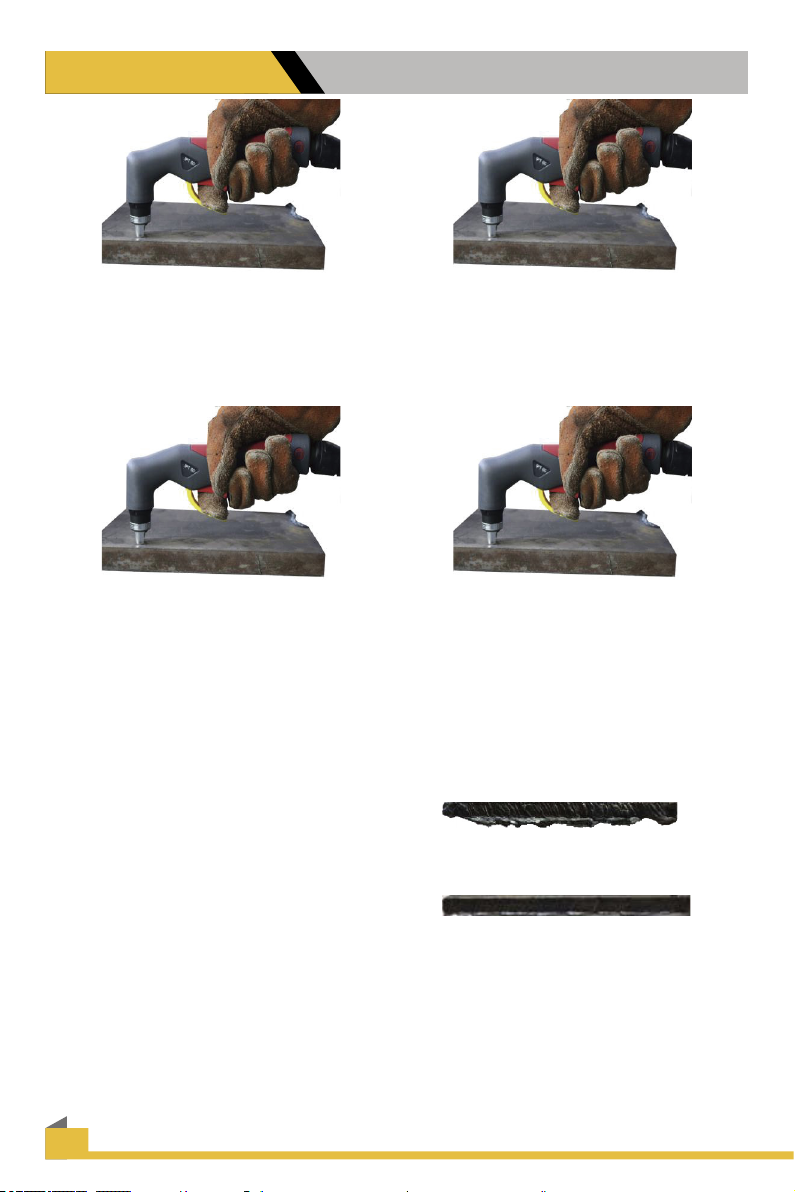
TIP: For longer consumable life do not use the pilot arc unnecessarily. Rapid wear will occur
if the pilot arc stays engaged more than 3 seconds at a time.
TRAVEL
FLAME AT NORMAL TRAVEL SPEED
TRAVEL
FLAME AT FAST TRAVEL SPEED
TRAVEL
FLAME AT SLOW TRAVEL SPEED
NOTE: When stepping down amps to cut thinner material, or using on 120V, you must
change to smaller orice nozzle for the best cutting results. Too large of an orice diameter
will result in arc instability and a rough cut. Lowering the air pressure below 50 psi to try to
get the torch to cut will only result in a lazy, wandering arc or an arc that sputters on and o
continuously.
TIP
IMPORTANT: Check consumables regularly for wear and change them out before they
are completely worn. Allowing the consumables to wear until they quit working may damage
related torch components, creating a more costly repair.
Table of contents
Other PrimeWeld Welding System manuals


