PrimeWeld CUT50DP User manual

MODEL: CUT50DP
Please Call
856-537-4368
www.primeweld.com
Need Help
OWNER`S
MANUAL

PLASMA CUTTER OPERATION MANUAL
CONTENTS
Dear Valued Customer. Thank you for purchasing our Plasma
Cutter Read this manual thoroughly. Incorrectly installed or
improperly grounded equipment is a hazard. And can cause
serious damage. Properly install and ground this equipment
according to this manual and national. State. And local codes.
Safety...................................................................................02
Main Parameter.................................................................07
Layout..................................................................................09
Operation............................................................................12
Trouble Shootting..............................................................17
Accessories ........................................................................20
EC DECLARATION OF CONFORMITY
We hereby declare that our machines for industrial and
professional use as stated below.
Model: IGBT plasma cutting machine Cut50dp, CUT5OPi,
CUT50D,CUT5ODP. Conforms with EMC Directives:
73/23/EEC and 89/336/EEC European Standard:
EN/IEC60974
Please read and understand this instruction manual
carefully before the installation and operation of this
equipment.
The contents of this manual may be revised without prior
notice and without obligation.
This instruction manual is issued on 05st May 2019.
01
PLASMA CUTTER OPERATION MANUAL
SAFETY
Welding and cutting is dangerous to the operator،people in or near the working
and surrounding areas, if the equipment is not operated correctly. Therefore the
performance of welding/cutting must only be under the strict and
comprehensive observance of all relevant safety regulations.
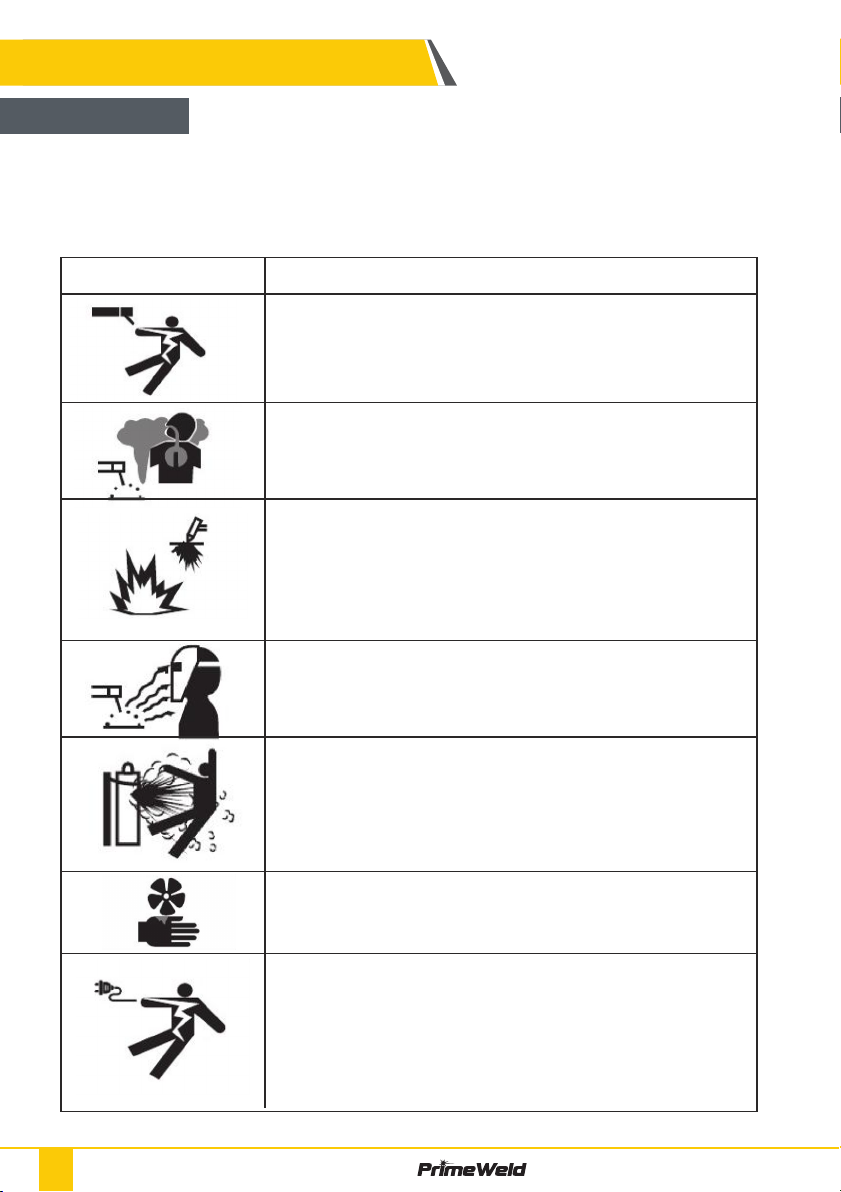
WARNING
Electric Shock: Maybe fetal
• Avoid all contact with live components of the welding circuit,
Electrodes and Wires with bare bands. Wear dry gloves before
start welding task.
• Wires with bare bands Keep operator insurance from welding
metal and welding pieces.
Smoke and gas generated while welding or cutting Harmful to
health of people
• keep head distance away from gas.
• Avoid breathing the smoke and gas of welding or cutting.
• keep the working area in good ventilation.
Fire Hazard
work place.
ready to use it.
ARC light-emission: Harmful to the eyes & skin of people
• Wear a welding helmet, Anti-radiation glass and work clothes
while the welding Operation is performed.
• Keep working area in ventilation.
CYLINDER may explode if damaged.
• Always keep cylinders in an upright position securely chained to
• Never allow the electrode, electrode holder or any other
electrically `hot" parts to touch a cylinder
• Keep your face and head away from the cylinder valve outlet
when it to be opening.
Engine fan can hurt the hands
• Do not put your hands near the engine fan.
• Do not attempt to override the governor or idler by pushing on
the throttle Control rods while the engine is running.
ELECTRIC SHOCK can kill.
• Insulate yourself from work and ground using dry insulation.
Make certain the insulation is large enough to cover your full
area of physical.
• Ground the work or metal to be welded to a good electrical
ground.
• Never dip the electrode in water for cooling.
before working on the equipment.
• Install equipment in accordance with electric standard code.
Symbol Descripiton
02

SAFETY
CAUTION
1. Working Environment
1.1 The environment in which this welding equipment is installed
humidity.
1.2 When using the machine outdoors protect the machine from
direct sun light. rain water and snow etc:the temperature of
working environment should be maintained within -14'F to +
104°F.
1.3 Keep this equipment distant from the wall.
1.4 Ensure the working environment is well ventilated.
2.Safety Tips.
2.1 Ventilation
This equipment is small-sized, compact in structure, and of
The fan is used to dissipate heat generated by this equipment
during the welding operation.
Important: Maintain good ventilation of the louvers of this
equipment.
The minimum distance between this equipment and any other
objects in or near the working area should be 1ft. Good
ventilation is of critical importance for the normal performance
and service life of this equipment.
2.2 Thermal Overload protection.
temperature environment, poorly ventilated area or if the fan
malfunctions the Thermal Overload Switch will be activated and the machine
will cease to operate. Under this circumstance, leave the machine switched on
to keep the built-in fan working to bring down the temperature inside the
equipment. The machine will be ready for use again when the internal
temperature reaches safe level.
2.3 Over-Voltage Supply
Regarding the power supply voltage range of the machine, please refer to '
Main parameter table.
This equipment is of automatic voltage compensation, which enables the
maintaining of the voltage range within the given range. In case that the
possible to cause damage to the components of this equipment. Please ensure
your primary power supply is correct.
03
Fire Hazard
work place.
ready to use it.
PLASMA CUTTER OPERATION MANUAL

2.4 Do not come into contact with the output terminals while the machine is in
operation. An electric shock may possibly occur.
machine. In order to prevent any possible failure or fault of this welding
equipment, clean the dust at regular intervals with clean and dry compressed air
of required pressure.
Please note that: lack of maintenance can result in the cancellation of the
guarantee: the guarantee of this welding equipment will be void if the machine
sealing of the machine without the consent of an authorized representative of
the manufacturer.
Note:
• Our equipment as described in this manual conforms to all applicable rules
and regulations of the 'Low Voltage Directive' (European Council Directive
73/23/EEC) as set out and amended by Council Directive 93/68/EEC) and to the
National legislation for the enforcement of this Directive.
• Our equipment as described in this manual conforms to all applicable rules
and regulations of the European Council Directive 89/336/EEC. (EMC Directive)
and to the National legislation for he enforcement of this Directive.
Plasma cutters work by passing an electric arc through a air/gas that is passing
The electric arc elevates the temperature of the gas to the point that it enters a
gas. Scientists call this additional state plasma. As the metal being cut is part of
the cireuit, the electrical conductivity of the plasma causes the arc to transfer to
the work. The restricted opening (nozzle) the gas passes through causes it to
squeeze by at a high speed, like air passing through a venturi in a carburettor.
This high speed gas cuts through the molten metal.
Plasma cutting was invented as the result of trying to develop a better welding
process. Many improvements then led to making this technology what it is today.
Plasma cutter equipment. For your safety and to avoid Electrical Shock. please
observe all safety notes and precautions detailed in this manual.
SAFETY
Maintenance
Air plasma cutting technology
Trouble shooting
04 PLASMA CUTTER OPERATION MANUAL
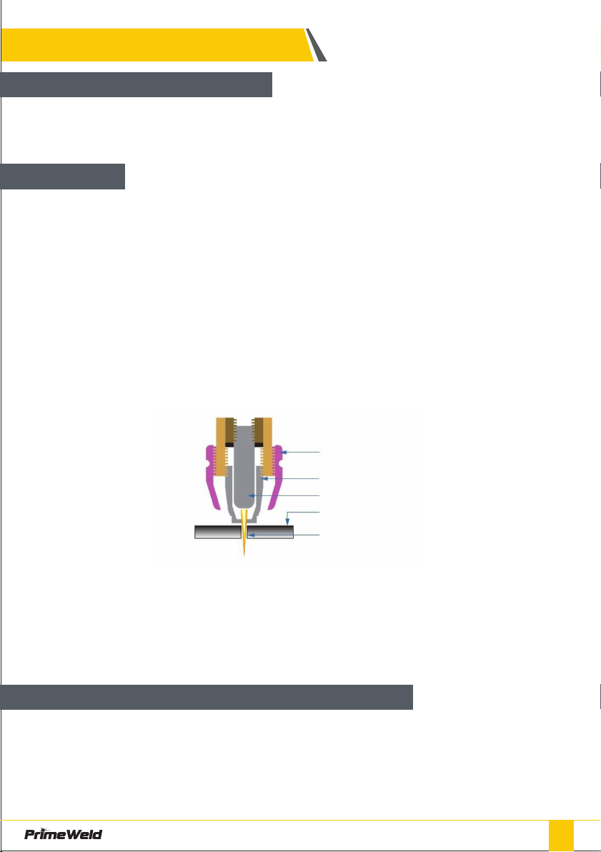
AG-60 / AG60P
Shield Cup
Nozzle
Electrode
Steel
Plasma Stream
Basic plasma cutters use electricity to superheat air into plasma (the 4th state of
matter), which is then blown through the metal to be cut. Plasma cutters require
a compressed air supply and AC power to operate.
SAFETY
How a plasma Cutter works
nozzle.
cutting nozzle.
supply increases voltage in order to maintain a constant current through the
joint.) Electrons arc across the gap. ionizing and super heating the air creating
a plasma stream.
Notes:
The nozzle and electrode require periodic replacement. The electrode has an
insert of tough high conductive material such as hafnium and cerium. This insert
Quality of the air used is paramount to longer life of electrodes and nozzles, in
short clean dry air gives longer parts life, the cleaner and dryer the better. We
recommend use of a Plasma Air Filter.
Operation
Virtually any metal can be plasma cut including steel, stainless steel, aluminium,
brass, copper, etc. Any thickness from 30 gauge through 13116" can be cut,
depending on the power of the plasma cutter used.
What kinds of materials can the plasma cut?
05
PLASMA CUTTER OPERATION MANUAL

SAFETY
Plasma cutting can be performed on any type of conductive metal - mild steel,
and thus it can cut aluminium, stainless and any other conductive material. While
compressed air for the plasma gas. In most shops, compressed air is readily
operation. Plasma cutting is typically easier for the novice to master, and on
plasma machines are required for plasma cutting applications.
How Does Plasma Cutting Compare to Oxy-fuel (gas) cutting?
The plasma Cutting process involves creating and electrical channel of
super¬heated. electrically ionized gas i.e. plasma from the plasma cutter itself,
through the work piece to be cut, thus forming a completed electric circuit back
to the plasma cutter via a grounding clamp. This is accomplished by a
which is blown through a focused nozzle at high speed toward the work piece. An
electrical arc is the formed within the gas. between an electrode near or
integrated into the gas nozzle and the work piece itself. The electrical arc ionizes
some of gas. thereby creating and electrically conductive channel of plasma. As
heat to melt through the work piece. At the same time, much of the high velocity
plasma and compressed gas blow the hot molten metal away. thereby separating
i.e. cutting through the work piece.
NOTE: This machine is designed to use only compressed air as gas.
Plasma Introduction
generally cut thicker sections (>63164 inch) of steel more quickly than plasma.
What are the limitations to Plasma Cutting?
Where is Oxyfuel preferred?
06 PLASMA CUTTER OPERATION MANUAL
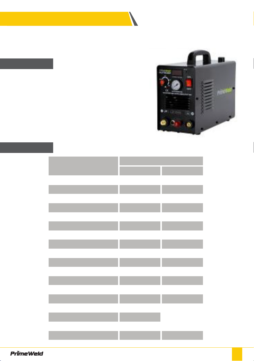
07
Cut50dp with 50 Amps cutting current.
Inverter with Industrial Rated, Lightweight and Portable.
PARAMETER
• Latest IGBT Inverter Technology
• Safe torch connection
• Industrial application
• Tolerant to variable power supply
• Quality Air regulator with preset air pressure
• Suitable to cut all electrically conductive materials
• Light weight and compact
• Strong metal housing
Amperage
Amperage
Model
Power Supply / Phases (V-Ph)
Duty Cycle @ 78°F ( 25 C)
Input Current Range (A)
35-40 40-45
Rated Power (KVA) 5.90 4.40
Output Current Range (A) 20-50 Amps 20-40 Amps
Rated Output Voltage (V) 100 96
No-Load Voltage (Open CricuC(V)
260 260
60 60
Insulation Class F F
Protection Class IP21S IP21S
Plasma Arc Starting
Air Flow Pressure Range (PSI) 40 - 65 psi 40 - 65 psi
Air Flow Rate (CFM) 5 L/min 5 L/min
Clean Cutting Thickness (mm) 12mm 12mm
Cutting Thickness Severance (mm)
16mm065psi 12mm065psi
Shipping Weight (kgs)
8.9kgs 8.9kgs
Cutting speed 10mm
200mm/min(065 psi 150mm/minG65 psi
Machine Dimenswns (inch)
Cut5ODP (110/220V)
220V 110V
PLASMA CUTTER OPERATION MANUAL

PARAMETER
Need to adjust the current and air pressure properly under metal thickness to
get best cutting surface
GENERAL DESCRIPTION
This unit is designed for light cutting project and weights only 11 kgs include
accessories. This powerful unit is good enough to cut 12mm ( 75PSI air pressure )
to 16mm severance thickness, making it an good idea for cost conscious DIY
hobbyists.
1. 50Amps inverter plasma cutter
3. suitable for stainless steel. Alloy steel, Mild steel. Copper and Aluminum, etc.
Cutting Thickness chart
SPECIFICATIONS
Cut50dp -220V 50Amps
12mm
20Amps 30Amps 40Amps
5mm 6mm 10mm
40-50psi 40-50psi 50-60psi 60-70psi
Thickness (mm)
Air Pressure (psi)
1
Cut50dp -110V
Thickness (mm)
Air Pressure (psi)
2
20Amps 30Amps 40Amps
5mm 6mm 10mm
40-50psi 40-50psi 50-60psi
Power source
Consumables AG60 Cutting Torch
Earth Clamp & Cable Air hose
08 PLASMA CUTTER OPERATION MANUAL

09
LAYOUT
How to install machine
Power Switch
Current Display
Current knob
Connecting torch to machine
Torch switch
For Pilot arc
Earth Clamp
Air Pressure Display
G1/4 Screw Air Connector
Fan
Input power cable
Air hose
Air regulator
PLASMA CUTTER OPERATION MANUAL

LAYOUT
Connection
Air Pressure
Current Knob
Torch connector Torch switch Earth Clamp
For Pilot arc
Power Switch
Display
Air Compressor
Air regulator
Input power
Earth clamp
Metal Piece
Torch
10 PLASMA CUTTER OPERATION MANUAL

11
LAYOUT
Back Connection
Explosive View of Machine
Air Compressor
Air regulator Input power
Regulator
Air Plug
Fan
Top PCB Air Meter
Case
Knob
Earth Socket
Torch Switch
Torch plug
Front Piece
Foot
Bottom case
Electric Valve
Cable Clamp
Power Switch
Center
PCB
Digital
PCB
Front Sticker
PLASMA CUTTER OPERATION MANUAL
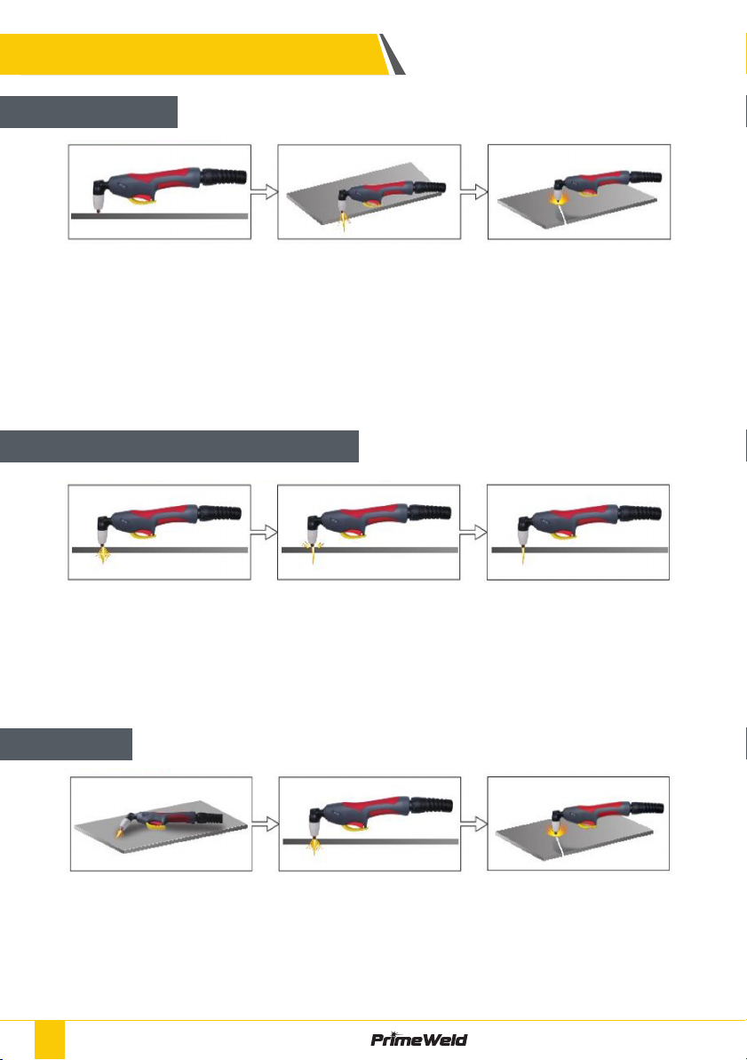
OPERATION
Start Cutting
Hand Torch cutting technique
Piercing
at the odge Of he work
piece
Then. Proceed with
the cut.
Pull the Trigger to start
the arc , the cutting arc
will initial when the
Torch tip is close
enough to the work
Piece. Start Cutting on
the edge until the Arc
has cut completely
through.
When cutting make
sure that sparks are
bottom of the work
piece.
vertical and watch
thearc as it cuts
along the line.
If sparks are spraying
up from the work
Piece, you are
moving the torch too
fast, or you don't
have enough amps
sel.
angle to the work
piece, pull the trigger
to start the arc and
slowly rotate it to an
upright position.
When the pierce is
complete, proceed
with cutting
When sparks are
bottom of the work
piece, the arc has
pierced through the
material
12 PLASMA CUTTER OPERATION MANUAL

13
OPERATION
How to use air regulator
Machine Dimensions
Clockwise increase air pressure
Pull up Pull down
Air regulator
Water release
Anti-Clockwise Reduce air pressure
143mm 348mm
234mm
PLASMA CUTTER OPERATION MANUAL

OPERATION
Standard rule of thumb is the thicker the material the more amperage required.
On thick material, set the machine to full output and vary your travel speed.
On thinner material, you need to turn down the amperage and change to a
lower-amperage tip to maintain a narrow kerf. The kerf is the width of the cut
material that is removed during cutting.
Amperage
Amperage and speed are critical to producing a good quality cut. The faster you
move (especially on aluminium), the cleaner your cut will be. To determine if
you're going too fast or too slow, visually follow the arc that is coming from the
the direction of travel. If it's going straight down. that means you're going too
slow. and you'll have an unnecessary buildup of dross or slag. If you go too fast, it
will start spraying back onto the surface of the material without cutting all the
way through. Because the arc trails at an angle, at the end of a cut, slow your
cutting speed and angle the torch in to cut through the last bit of metal.
Speed
It is easier to pull the torch towards you than push it. The plasma stream swirls
material and needs to taken into consideration before starting your cut as you
Direction
Torch tip height & position
bevel is by cutting at the proper speed and height for the material and amperage
that is being cut.
Correct torch height and
Square to the material
Minimum bevel & equal
bevel Longest
consumable life
Torch Angled to the
material unequal bevel,
one side may be
14 PLASMA CUTTER OPERATION MANUAL

15
OPERATION
at lower settings for use on thin-gauge material. Using a 25 amp tip at an 60 amp
Conversely. using an 80-amp tip on the lower settings will not allow you to focus
produce a distorted plasma stream resulting in a poor cut quality.
Tip size and condition
Electrons arc across the gap, ionizing and super heating the air creating the
plasma stream. The electrode contains an insert in the end made of a highly
conductive material called hafnium. This insert erodes with use and develops a
pit in the end of the electrode, when the pit becomes too much poor quality cuts
will result and necessitate replacement of the electrode.
Electrode condition
consumable life span.The required air pressure and volume can vary from model
to model and the manufacturer will provide the specs.The primeweld cut50 air
capacity of your compressor is important. if you have a small compressor with
continuously when you are plasma cutting. a compressor with a l/min rating
slightly higher than the plasma would be more adequate. If you are doing a lot of
cutting, cutting thick plate (same air consumption but slower cut speeds = longer
cut time) then choose a compressor at 1.5 to 2 times the plasma system
requirement.
Air pressure and volume
Torch height too high
Stream may not cut all the
way through the material
Torch height too low Reverse
bevel. Tip may contact the work
piece and short out or damage
the tip.
PLASMA CUTTER OPERATION MANUAL

Good air quality is essential to quality plasma cutting and consumable life span.
Compressors take in air at atmospheric pressure and increase the pressure and
producing water, more so in humid environments. Moisture that forms in air
lines has a tendency to condense into larger drops when the air pressure
decreases as it is entering the plasma torch. When these droplets enter into the
high temperatures (as much as 19832°f) in the plenum of the torch, they immedi-
content of air in the torch. These elements will then dramatically change the
plasma arc which causes the torch consumable parts to wear very quickly, alters
squareness, dross formation, and edge smoothness. Minimising the moisture in
the air supply is absolutely critical to quality plasma cuts and longevity of
consumable parts. As a minimum be sure to drain the receiver (tank) on the air
compressor at least daily. Most air plasma systems from reputable manufactur-
drain that will remove some moisture from the air supply. For home workshop
quality of the plasma cutter and in most cases it is recommended to install a sub
changed after it is near saturation, it should be installed close as possible to the
air intake of the plasma cutter.
•It is easier to pull the torch through the cut than to push it.
•To cut thin material reduce the amperage until you get the best quality cut.
•For Straight cuts use a straight edge or cutting buggy as a guide. For circles, use
a template or circle cutting attachment.
•Check that the front end consumable parts of the plasma cutting torch are in
good condition.
OPERATION
Air Quality
Technique Tips
Torch Connector cover
16 PLASMA CUTTER OPERATION MANUAL

17
1. Power indicate not
lighting when power up
, the fan not working ,
torch also not working
while press torch trigger
No power go into
machine through power
cable(AC220 orAC110)
no input
2.Power cable, switch or
other wire loosen
3.Power cable inside of
machine connect not
well
4.Power board problem
2.Check the power
cable: power switch,
power plug and all wires
inside of machine if any
loosen, check if any
wires loosen from
power switch to main
board.
3 Change the board
2. power indicator not
lighting up after switch
on , fan stop working
only works some
seconds, machine stop
working once the torch
touch the metal get arc
starting.
1.The starting circuit
problem, or relay
problem.
2.Too many times
machine over heat can
not get working
1 Check the power
components or change
the main board,.
2.Let the machine rest
some time restart it
again.
3. power indicator
lighting after switch on
machine, fan works, but
machine not working
while press torch trigger
1.Check the torch switch
or if any torch wires
loosen from torch
2.The torch switch
loosen or any wires
loosen
3. The switch wires
loosen inside of
machine for the torch
1 Check if any torch
2.Check if any wires
loosen on torch
3.Check if any wires
loosen inside of
machine
4. the power indicator
lighting, the fan works,
torch trigger but no air
blow out of torch head
or the air keep blowing
out ) The electric valve
not working
1.The electric valve
problem it is DC24V)
2.Maybe the air hose
stuck
3.The circuit for air valve
control problem
3.Check it:
4.Change the board,
Problems Analysis Solution
TROUBLE SHOOTTING
PLASMA CUTTER OPERATION MANUAL

TROUBLE SHOOTTING
5. Power indicator
lighting up, 0.0
indica¬tor not lighting,
Fan works, The gas blow
out of torch after
pressure torch trigger
( gas valve works )No
metal and electrode
broken
1.Check if any wires
loosen
capacitor.
6. Power indicator
lighting up, Fan works,
Gas blow out of torch
while pressing trigger,
0.0 lighting while
pressing torch trigger
1.Diode problem :
a1.Check every diode,
replace it if any
damaged 2.Check every
IGBT to see If any one
damaged
, Regisistor. Diode,
Replace it if any one
damaged
7. Power indicator
lighting , Fan works, Air
can blow out of torch
head after press torch
trigger, 0.0 indicator not
lighting, But it is lighting
up while cutting.
Check IC3140 and other
compoents
if any wires loosen.
2.Does the feedback
wire loosen or broken ,
Check and replace.
3.Replace the board.
8. The cutting current
can not be adjust
1.The wires loosen or
potentiometer
damaged
2.The setting circuit
problem.
1. Check the
potentiome¬ter if
middle pin to earth get
0-5V voltage. Replace it
if any damaged
2. Check if any wires
loosen from front board
to main board
3. Boards problem0
Problems Analysis Solution
18 PLASMA CUTTER OPERATION MANUAL

TROUBLE SHOOTTING
9. Machine auto shut
down after switch it on.
1.Maybe Power cable or
circuit board short
circuit
2.Silicon bridge probـ
lem
2.Check and replace it
3.Replace silicon bridge
10. After pressure torch
sound and spark, but
can not get arc start
starting not good
enough
0
after press torch switch
1.Welding torch broken
or loosen or Earth
clamp and cable
connecting not good
enough to the earth and
2.The connector for
positive or negative
loosen
1.The Gap for tip to the
metal not in good range,
The tip and electrode
3.GAS/AIR connector
damaged, power
leakage between
connector and front
panel
torch switch board and
disturb it.
1.Adjust the tip to metal
1.Check the GAS/AIR
torch connector, earth
female socket and torch
switch connector, if
between them to front
metal
Problems Analysis Solution
19
PLASMA CUTTER OPERATION MANUAL
Table of contents
Other PrimeWeld Welding System manuals


Popular Welding System manuals by other brands


Hobart Welding Products
Hobart Welding Products AirForce 375 owner's manual

GF
GF MSA 330 instruction manual

Hakko Electronics
Hakko Electronics FX-888D instruction manual

Abicor Binzel
Abicor Binzel ABIPLAS WELD 100 W operating instructions

EWM
EWM Taurus 355 Basic TDM operating instructions

Thermal Dynamics
Thermal Dynamics PakMaster 100 XL plus operating manual


