manuals.online logo
Brands
  1. Home
  2. •
  3. Brands
  4. •
  5. Pro-Form
  6. •
  7. Exercise Bike
  8. •
  9. Pro-Form 790 E User manual

Pro-Form 790 E User manual

Other manuals for 790 E

3

This manual suits for next models

1

Other Pro-Form Exercise Bike manuals

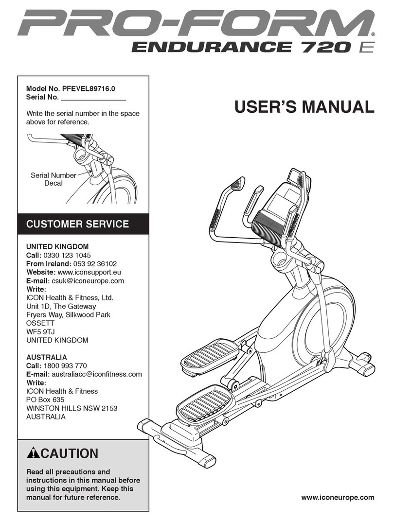
Pro-Form endurance 720 e User manual

Pro-Form

Pro-Form endurance 720 e User manual

Pro-Form SR 20 User manual

Pro-Form

Pro-Form SR 20 User manual

Pro-Form LE TOUR DE FRANCE CLC User manual

Pro-Form

Pro-Form LE TOUR DE FRANCE CLC User manual

Pro-Form 180 Ur Bike User manual

Pro-Form

Pro-Form 180 Ur Bike User manual

Pro-Form 760 HR Heart Rate Control User manual

Pro-Form

Pro-Form 760 HR Heart Rate Control User manual

Pro-Form PFEX78918P.0 User manual

Pro-Form

Pro-Form PFEX78918P.0 User manual

Pro-Form GL 36 User manual

Pro-Form

Pro-Form GL 36 User manual

Pro-Form 750 Ekg Bike User guide

Pro-Form

Pro-Form 750 Ekg Bike User guide

Pro-Form 4.0 Es Bike User manual

Pro-Form

Pro-Form 4.0 Es Bike User manual

Pro-Form PFEX01416.1 User manual

Pro-Form

Pro-Form PFEX01416.1 User manual

Pro-Form 762 Ekg Bike User manual

Pro-Form

Pro-Form 762 Ekg Bike User manual

Pro-Form Le Tour De France PFEVEX71919.0 User manual

Pro-Form

Pro-Form Le Tour De France PFEVEX71919.0 User manual

Pro-Form XP WhirlWind 280 User manual

Pro-Form

Pro-Form XP WhirlWind 280 User manual

Pro-Form 1550cwi System manual

Pro-Form

Pro-Form 1550cwi System manual

Pro-Form 715 Smr Bike Operating and maintenance manual

Pro-Form

Pro-Form 715 Smr Bike Operating and maintenance manual

Pro-Form 800 Tr Intrac Erg Bike Operating and maintenance manual

Pro-Form

Pro-Form 800 Tr Intrac Erg Bike Operating and maintenance manual

Pro-Form 928L User manual

Pro-Form

Pro-Form 928L User manual

Pro-Form 440 ES User manual

Pro-Form

Pro-Form 440 ES User manual

Pro-Form 831.280440 User manual

Pro-Form

Pro-Form 831.280440 User manual

Pro-Form 200 Zlx Bike User manual

Pro-Form

Pro-Form 200 Zlx Bike User manual

Pro-Form PFEX14914.0 User manual

Pro-Form

Pro-Form PFEX14914.0 User manual

Pro-Form 990S User manual

Pro-Form

Pro-Form 990S User manual

Pro-Form PFCCEX34390 User manual

Pro-Form

Pro-Form PFCCEX34390 User manual

Pro-Form 135 CSX User manual

Pro-Form

Pro-Form 135 CSX User manual

Popular Exercise Bike manuals by other brands

BH BLADEZ 200U owner's manual

BH

BH BLADEZ 200U owner's manual

Eco-De ECO-800 Instruction guide

Eco-De

Eco-De ECO-800 Instruction guide

Nautilus Be Strong Commercial Series U916 owner's manual

Nautilus

Nautilus Be Strong Commercial Series U916 owner's manual

NordicTrack Gx 3.1 Bike Manual Del Usuario

NordicTrack

NordicTrack Gx 3.1 Bike Manual Del Usuario

NordicTrack Gx 3.1 Bike Instrukcja obsŁugi

NordicTrack

NordicTrack Gx 3.1 Bike Instrukcja obsŁugi

Tomahawk IC3 manual

Tomahawk

Tomahawk IC3 manual

GPI Sports & Fitness BODYWORX ABX250M manual

GPI Sports & Fitness

GPI Sports & Fitness BODYWORX ABX250M manual

Trixter X-Bike user manual

Trixter

Trixter X-Bike user manual

TOORX BRX85 Instruction

TOORX

TOORX BRX85 Instruction

Matrix KranKcycle user manual

Matrix

Matrix KranKcycle user manual

Weslo Vector 302 Bedienungsanleitung

Weslo

Weslo Vector 302 Bedienungsanleitung

Matrix IC3 manual

Matrix

Matrix IC3 manual

Sunny Health & Fitness SF-B121021 user manual

Sunny Health & Fitness

Sunny Health & Fitness SF-B121021 user manual

Monark 827E instruction manual

Monark

Monark 827E instruction manual

Stamina 1310 owner's manual

Stamina

Stamina 1310 owner's manual

American Fitness SPR-BK1072A owner's manual

American Fitness

American Fitness SPR-BK1072A owner's manual

Cateye CS-1000 (CYCLO SIMULATOR) Service manual

Cateye

Cateye CS-1000 (CYCLO SIMULATOR) Service manual

BH FITNESS H9158H Instructions for assembly and use

BH FITNESS

BH FITNESS H9158H Instructions for assembly and use

manuals.online logo
manuals.online logoBrands
  • About & Mission
  • Contact us
  • Privacy Policy
  • Terms and Conditions

Copyright 2025 Manuals.Online. All Rights Reserved.

USER'S MANUAL
CAUTION
Read all precautions and instruc-
tions in this manual be ore using
this equipment. Keep this manual
or uture re erence.
a
a
a
a
a
aa
a
aa
aaa
a
a
a
aaa
a
aa
a
a
a
a
aa
aa
a
a
a
aa
a
a
aa
a
a
a
a
a
aa
a
a
aa
a
aa
a
QUESTIONS?
As a manu acturer, we are com-
mitted to providing complete
customer satis action. I you
have questions, or i there are
missing or damaged parts, we
will guarantee complete satis ac-
tion through our Customer
Service Department.
Please CALL:
0345-089009
Or WRITE:
ICON Fitness Li estyle Ltd.
Greenwich House
223 North Street
Sheepscar
West Yorkshire
Leeds LS7 2AA
Model No. PFEVEX10890
Serial No.
Write the serial number in the
space above for future reference.
Class HC Fitness Product
Serial
Number
Decal
Visit our website at
www.pro orm.com
new products, prizes,
fitness tips, and much more!
®
2
TABLE OF CONTENTS
IMPORTANT PR CAUTIONS . . . . . . . . . . . . . . . . . . . . . . . . . . . . . . . . . . . . . . . . . . . . . . . . . . . . . . . . . . . . .3
B FOR YOU B GIN . . . . . . . . . . . . . . . . . . . . . . . . . . . . . . . . . . . . . . . . . . . . . . . . . . . . . . . . . . . . . . . . . . .4
ASS MBLY . . . . . . . . . . . . . . . . . . . . . . . . . . . . . . . . . . . . . . . . . . . . . . . . . . . . . . . . . . . . . . . . . . . . . . . . . . .5
HOW TO US TH X RCIS CYCL . . . . . . . . . . . . . . . . . . . . . . . . . . . . . . . . . . . . . . . . . . . . . . . . . . . . . .8
MAINT NANC AND TROUBL -SHOOTING . . . . . . . . . . . . . . . . . . . . . . . . . . . . . . . . . . . . . . . . . . . . . . . .10
CONDITIONING GUID LIN S . . . . . . . . . . . . . . . . . . . . . . . . . . . . . . . . . . . . . . . . . . . . . . . . . . . . . . . . . . . .11
PART LIST . . . . . . . . . . . . . . . . . . . . . . . . . . . . . . . . . . . . . . . . . . . . . . . . . . . . . . . . . . . . . . . . . . . . . . . . . . .14
XPLOD D DRAWING . . . . . . . . . . . . . . . . . . . . . . . . . . . . . . . . . . . . . . . . . . . . . . . . . . . . . . . . . . . . . . . . .15
HOW TO ORD R R PLAC M NT PARTS . . . . . . . . . . . . . . . . . . . . . . . . . . . . . . . . . . . . . . . . . . .Back Cover
®
PROFORM®is a registered trademark of ICON Health & Fitness, Inc.
3
IMPORTANT PRECAUTIONS
WARNING: To reduce the risk o serious injury, read the ollowing important precautions be ore
using the PROFORM®790 exercise cycle.
1. Read all instructions in this manual be ore
using the exercise cycle. Use the exercise
cycle only as described.
2. It is the responsibility o the owner to ensure
that all users o the exercise cycle are ade-
quately in ormed o all precautions.
3. Use the exercise cycle indoors, away rom
moisture and dust. Place the exercise cycle
on a level sur ace, with a mat beneath it to
protect the loor or carpet rom damage.
4. Inspect and tighten all parts regularly.
Replace any worn parts immediately.
5. Keep children under the age o 12 and pets
away rom the exercise cycle at all times.
6. The exercise cycle should not be used by
persons weighing more than 250 pounds
(115 kg).
7. Wear appropriate clothing when exercising;
do not wear loose clothing that could become
caught on the exercise cycle. Always wear
athletic shoes or oot protection.
8. The pulse monitor is not a medical device.
Various actors, including the user's move-
ment, may a ect the accuracy o heart rate
readings. The pulse monitor is intended only
as an exercise aid in determining heart rate
trends in general.
9. Always keep your back straight when using
the exercise cycle. Do not arch your back.
10.I you eel pain or dizziness at any time
whilst exercising, stop immediately and
begin cooling down.
11. The exercise cycle is intended or in-home
use only. Do not use the exercise cycle in a
commercial, rental or institutional setting.
12.The decal shown below has been placed on
the exercise cycle. I the decal is missing, or
i it is not legible, please call our Customer
Service Department at 0345-089009 to order
a ree replacement decal. Apply the decal in
the location shown.
WARNING: Be ore beginning this or any exercise program, consult your physician. This is espe-
cially important or persons over the age o 35 or persons with pre-existing health problems. Read
all instructions be ore using. ICON assumes no responsibility or personal injury or property dam-
age sustained by or through the use o this product.
4
BEFORE YOU BEGIN
Thank you for selecting the innovative PROFORM®
790 exercise cycle. Cycling is one of the most popular
and effective exercises for improving cardiovascular
fitness and toning the body. The PROFORM®790
blends advanced engineering with contemporary
styling to let you enjoy the benefits of this exercise in
the convenience and privacy of your home.
Please read this manual care ully be ore you use
the PROFORM®790. I you have additional ques-
tions, please call our Customer Service Department at
0345-089009. To help us assist you, please mention
the product model number and serial number when
calling. The model number is PF V X10890. The ser-
ial number can be found on a decal attached to the
PROFORM®790 (see the front cover of this manual
for the location of the decal).
Before reading further, please familiarise yourself with
the parts that are labelled in the drawing below.
Handlebars
Pulse Sensor
Water Bottle Holder
(bottle not included)
Resistance Knob
FRONT
BACK RIGHT SIDE
Seat Knob
Seat
Seat Post
Pedal
Console
Front Wheels
Side Shield
Adjustable ndcap
Place all parts of the exercise cycle in a cleared area and remove the packing materials. Do not dispose of the
packing materials until assembly is completed.
Assembly requires the included allen wrench and screw tool as well as a phillips
screwdriver and two adjustable spanners .
Use the chart below for help identifying the small parts used in assembly. The number in parenthesis below each
part refers to the key number of the part, from the PART LIST on page 14. The second number refers to the
quantity used for assembly. Note: Some parts may have been pre-attached or shipping purposes. I a part
is not ound in the parts bag, check to see i it has been pre-attached.
5
ASSEMBLY
M10 x 22mm Button Screw (55)–5
M10 Nylon Locknut (44)–4
M8 Nylon Locknut (56)–3
M4 x 16mm Screw (7)–4 M8 Lock Washer (59)–3 M10 Lock Washer (61)–5
M10 x 75mm Carriage Bolt (54)–4
1. The Console (5) requires two 1,5V batteries (not
included). Alkaline batteries are recommended. Refer
to the inset drawing. Locate and open the battery
cover on the back of the Console. Press two batter-
ies into the battery compartment. Make sure that
the negative ends o the batteries (marked “–”)
are touching the springs in the battery compart-
ment. Close the battery cover.
Insert the console wire through the Handlebar Post
(19). Attach the Console (5) to the Handlebar Post
with four M4 x 16mm Screws (7).
15
5
19
7
7Batteries
Battery
Cover
Console
Wire
6
5
5. Make sure that there are Round ndcaps (15) on
the ends of the Rear Stabiliser (16).
Hold the Rear Stabiliser (16) against the saddle on
the rear of the Frame (13), with the square holes
facing away from the saddle. Attach the Rear
Stabiliser with two M10 x 75mm Carriage Bolts (54)
and two M10 Nylon Locknuts (44).
4
4. Make sure that there are Adjustable ndcaps (25)
on the ends of the Front Stabiliser (27).
Hold the Front Stabiliser (27) against the saddle on
the front of the Frame (13). Make sure that the
Front Stabiliser is turned so the Wheels (26) are
not touching the loor. The Wheels should touch
the floor only when the exercise bike is tipped for
moving. Attach the Front Stabiliser with two M10 x
75mm Carriage Bolts (54) and two M10 Nylon
Locknuts (44).
27
25
26
26 25
44
13
54
13
54
44
15
16
Square
Holes
15
3. Attach the Handlebar (18) to the Handlebar Post
(19) with two M10 x 22mm Button Screws (55) and
two M10 Lock Washers (61).
3
19
61
55
18
2. Refer to drawing 2a. Locate the sheath and make
sure that it remains on the Cable Connector (43).
Insert the tip of the Upper Resistance Cable (6) into
the opening in the Cable Connector as shown in the
inset drawing. Pull up on the Upper Resistance Cable
and insert it into the top of the Cable Connector.
Center the sheath on the Cable Connector.
Connect the console wire to the Reed Switch Wire
(4). Slide the Handlebar Post (19) into the Frame
(13), making sure not to pinch any o the wires
or cables. Attach the Handlebar Post with three
M10 x 22mm Button Screws (55) and three M10
Lock Washers (61).
61 61
55
55
13
4
19
43
74
6
Console
Wire
6
43
Tip
2a
Insert
Here
Sheath
Sheath
2
7
8. Make sure that all parts are tightened be ore you use the exercise cycle. Note: There may be some
hardware le t over a ter assembly is completed. To protect the floor from damage, place a mat beneath
the exercise cycle.
7. Identify the Left Pedal (20); there is an “L” on the
Left Pedal for identification. Using an adjustable
wrench, tighten the Left Pedal counterclockwise into
the left side of the Crank (70).
Tighten the Right Pedal (not shown) clockwise into
the right side of the Crank (not shown).
7
6. Turn the Seat Knob (3) counterclockwise several
turns to loosen it. Next, pull back the Seat Knob and
insert the Seat Post (9) into the Frame (13). Slide
the Seat Post to the desired height and release the
Seat Knob. Move the Seat Post up or down
slightly until it locks into place. Press the Seat
Collar (10) into the Frame (13). Turn the Seat Knob
clockwise to tighten it.
Next, attach the Seat (8) to the Seat Post (9) with
the three M8 Nylon Locknuts (56) and M8 Lock
Washers (59). Note: The M8 Nylon Locknuts and
M8 Lock Washers may be pre-attached to the bot-
tom of the Seat.
13
20
70
9
56 56
59 59
10
8
3
6
HOW TO ADJUST THE SEAT
For effective exer-
cise, the Seat (8)
should be at the
proper height; as
you pedal, there
should be a slight
bend in your knees
when the pedals
are at the lowest
position. To adjust
the Seat, first turn
the Seat Knob (3)
counterclockwise
several turns to loosen it. Next, pull back the Seat
Knob, slide the Seat Post (9) to the desired height,
and release the Seat Knob. Move the Seat Post up
or down slightly until it locks into place. Turn the
Seat Knob clockwise to tighten it.
HOW TO ADJUST THE PEDALLING RESISTANCE
To vary the intensi-
ty of your exercise,
the resistance of
the pedals can be
changed with the
Resistance Knob
(53). To increase
the resistance, turn
the Resistance
Knob clockwise; to
decrease the resis-
tance, turn the Resistance Knob counterclockwise.
HOW TO ADJUST THE PEDAL STRAPS
To adjust each
Pedal Strap (45,
50), pull the Pedal
Strap off the tab
on the pedal. Align
the desired hole in
the Pedal Strap
with the tab and
press the Pedal
Strap back onto the tab.
HOW TO APPLY AN INFORMATION DECAL TO
THE CONSOLE
All of the informa-
tion on the con-
sole is printed in
nglish. The
included decal
sheet contains
the same infor-
mation in five
other languages.
If nglish is not
your native lan-
guage, locate the
decal on the
decal sheet that
is printed in your
native language.
Next, peel the
information decal
off the decal
sheet. Apply the
decal to the
console in the
location shown.
BATTERY INSTALLATION
Before the console can be operated, two 1,5V
batteries must be installed. If you have not installed
batteries, see assembly step 1 on page 5. Note: It will
be necessary to remove the console in order to install
batteries.
8
HOW TO USE THE EXERCISE CYCLE
8
9
3
53
Tab
45
Decal
9
DIAGRAM OF THE CONSOLE
The console offers six modes that provide instant
exercise feedback. ach mode is displayed for five
seconds in a repeating cycle. The modes are
described below.
Pulse—This mode displays your heart rate
when the pulse sensor is used.
Calorie—This mode displays the approximate
number of calories you have burned.
Fat Calorie—This mode displays the approxi-
mate number of fat calories you have burned.
(See BURNING FAT on page 11.)
Speed—This mode displays your pedaling
speed, in kilometers per hour.
Time—This mode displays the length of time
you have exercised.
Distance—This mode displays the total number
of kilometers you have pedaled during your
workout.
HOW TO OPERATE THE CONSOLE
1. To turn on the
power, press the
on/reset button
or simply begin
pedaling. When
the power is
turned on, the
entire display
will appear for two seconds. The console will then
be ready for operation.
2. When the power
is turned on, the
console will
begin displaying
all modes in a
repeating cycle
(except for the
pulse mode).
Flashing arrows will show which mode is currently
displayed.
3. To measure your
pulse, stop ped-
aling and place
your thumb on
the pulse sensor
as shown. The
pulse sensor is
pressure-activat-
ed—fully press down the pulse sensor. Do not
press too hard, or the circulation in your thumb
will be restricted, and your pulse will not be
detected. Next, slightly raise your thumb until the
heart-shaped indicator in the display flashes
steadily. Hold your thumb at this level. After 5 to 10
seconds, three dashes will appear in the display and
your pulse will then be shown. Hold your thumb on
the sensor for another 15 seconds for the most
accurate reading. If the displayed pulse appears to
be too high or too low, or if your pulse is not dis-
played, lift your thumb off the sensor and allow the
display to reset. Press down again on the sensor as
described above.
Make sure that your thumb is positioned as shown,
and that you are applying the proper amount of pres-
sure to the pulse sensor. Try the sensor several
times until you become familiar with it.
4. To reset the dis-
play, press the
on/reset button.
5. To turn o the power, simply wait or about six
minutes. Note: The console has an “auto-off”
feature. If the pedals are not moved and the con-
sole buttons are not pressed for six minutes, the
power will turn off automatically in order to con-
serve the batteries.
Arrow
10
Inspect and tighten all parts of the exercise cycle
regularly. Replace any worn parts immediately.
The exercise cycle can be cleaned with a soft, damp
cloth. Avoid spilling liquid on the console or the pulse
monitor. Keep the console out of direct sunlight or the
display may be damaged. Remove the battery when
storing the exercise cycle.
BATTERY REPLACEMENT
If the console does not function properly, the batteries
should be replaced (see assembly step 1 on page 5).
Note: It will be necessary to remove the console to
replace the batteries.
HOW TO LEVEL THE EXERCISE CYCLE
If the exercise cycle
does not sit flat on
the floor, try turning
one or both of the
Adjustable ndcaps
(25) at the front of the
exercise cycle until
the exercise cycle is
level.
HOW TO ADJUST THE REED SWITCH
If the console does not display correct feedback, the
reed switch should be adjusted. To adjust the reed
switch, the Left Side Shield (24) and the Flywheel
Cover (31) must be removed. Using an adjustable
wrench, turn the Left Pedal (20) clockwise and remove
it. Next, remove the indicated Screws (2, 32, 35, 49).
Turn the Crank (70) to the position shown and slide off
the Left Side Shield and the Flywheel Cover.
Next, locate the Reed Switch (4). Turn the crank until
the Magnet (33) is aligned with the Reed Switch.
Loosen but do not remove the indicated Screw (35).
Slide the Reed Switch slightly closer to or away from
the Magnet. Retighten the Screw. Turn the Crank for a
moment. Repeat until the console displays correct
feedback. When the Reed Switch is correctly adjust-
ed, re-attach the left side shield, flywheel cover and
left pedal.
MAINTENANCE AND TROUBLE-SHOOTING
25
24
20
2
35
35
49
70
31
32
35
70
4
33
Front View