manuals.online logo
Brands
  1. Home
  2. •
  3. Brands
  4. •
  5. Pro-Form
  6. •
  7. Treadmill
  8. •
  9. Pro-Form PCTL62590 User manual

Pro-Form PCTL62590 User manual

This manual suits for next models

1

Other Pro-Form Treadmill manuals

Pro-Form PFTL66906.0 User manual

Pro-Form

Pro-Form PFTL66906.0 User manual

Pro-Form PFTL99806.3 User manual

Pro-Form

Pro-Form PFTL99806.3 User manual

Pro-Form 831.297460 User manual

Pro-Form

Pro-Form 831.297460 User manual

Pro-Form C 990 User manual

Pro-Form

Pro-Form C 990 User manual

Pro-Form Performance 1450 User manual

Pro-Form

Pro-Form Performance 1450 User manual

Pro-Form PFTL72582 User manual

Pro-Form

Pro-Form PFTL72582 User manual

Pro-Form CrossTrainer PFTL57507.0 User manual

Pro-Form

Pro-Form CrossTrainer PFTL57507.0 User manual

Pro-Form PFTL05050 User manual

Pro-Form

Pro-Form PFTL05050 User manual

Pro-Form 580X INTERACTIVE TRAINER User manual

Pro-Form

Pro-Form 580X INTERACTIVE TRAINER User manual

Pro-Form 370p Treadmill

Pro-Form

Pro-Form 370p Treadmill

Pro-Form 595 Pi Treadmill User manual

Pro-Form

Pro-Form 595 Pi Treadmill User manual

Pro-Form 1200 Zlt Treadmill Operating and maintenance manual

Pro-Form

Pro-Form 1200 Zlt Treadmill Operating and maintenance manual

Pro-Form PETL79816.0 User manual

Pro-Form

Pro-Form PETL79816.0 User manual

Pro-Form Power 995 User manual

Pro-Form

Pro-Form Power 995 User manual

Pro-Form 490 C Treadmill User manual

Pro-Form

Pro-Form 490 C Treadmill User manual

Pro-Form 520 User manual

Pro-Form

Pro-Form 520 User manual

Pro-Form 785xt User manual

Pro-Form

Pro-Form 785xt User manual

Pro-Form PFTL39921.0 User manual

Pro-Form

Pro-Form PFTL39921.0 User manual

Pro-Form PFTL01299.2 User manual

Pro-Form

Pro-Form PFTL01299.2 User manual

Pro-Form 831.299412 User manual

Pro-Form

Pro-Form 831.299412 User manual

Pro-Form 520x User manual

Pro-Form

Pro-Form 520x User manual

Pro-Form XP Trainer 580 User manual

Pro-Form

Pro-Form XP Trainer 580 User manual

Pro-Form 905 Zlt Treadmill Reference guide

Pro-Form

Pro-Form 905 Zlt Treadmill Reference guide

Pro-Form 831.29604.0 User manual

Pro-Form

Pro-Form 831.29604.0 User manual

Popular Treadmill manuals by other brands

Motus M990T Service manual

Motus

Motus M990T Service manual

NordicTrack APEX4100i NTTL18906 user manual

NordicTrack

NordicTrack APEX4100i NTTL18906 user manual

CAPITAL SPORTS Pacemaker Touch manual

CAPITAL SPORTS

CAPITAL SPORTS Pacemaker Touch manual

Insportline Hill Pro user manual

Insportline

Insportline Hill Pro user manual

Expondo Gymrex GR-MG31 user manual

Expondo

Expondo Gymrex GR-MG31 user manual

HEALTH ONE Walk Ro user manual

HEALTH ONE

HEALTH ONE Walk Ro user manual

NordicTrack T7.5 S user manual

NordicTrack

NordicTrack T7.5 S user manual

Gold's Gym ADVANTAGE GGTL12920 user manual

Gold's Gym

Gold's Gym ADVANTAGE GGTL12920 user manual

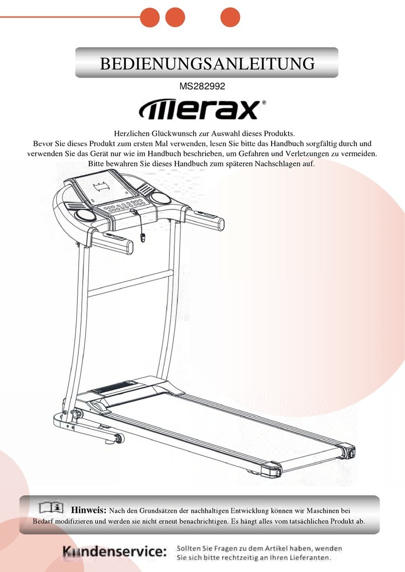
Merax MS282992 manual

Merax

Merax MS282992 manual

FitLogic freewill d225 owner's manual

FitLogic

FitLogic freewill d225 owner's manual

HOP-SPORT ESTIMA HS-3200LB instruction manual

HOP-SPORT

HOP-SPORT ESTIMA HS-3200LB instruction manual

Stamia InMotion II owner's manual

Stamia

Stamia InMotion II owner's manual

Smooth Fitness EVO 3i user manual

Smooth Fitness

Smooth Fitness EVO 3i user manual

NordicTrack NETL81810.0 user manual

NordicTrack

NordicTrack NETL81810.0 user manual

Schwinn 830/Journey 8.0 Assembly manual / owner's manual

Schwinn

Schwinn 830/Journey 8.0 Assembly manual / owner's manual

Keys Fitness HealthTrainer HT-740T owner's manual

Keys Fitness

Keys Fitness HealthTrainer HT-740T owner's manual

Spirit XT8 Service manual

Spirit

Spirit XT8 Service manual

NordicTrack T 14.0 Treadmill Manuel de l'utilisateur

NordicTrack

NordicTrack T 14.0 Treadmill Manuel de l'utilisateur

manuals.online logo
manuals.online logoBrands
  • About & Mission
  • Contact us
  • Privacy Policy
  • Terms and Conditions

Copyright 2025 Manuals.Online. All Rights Reserved.

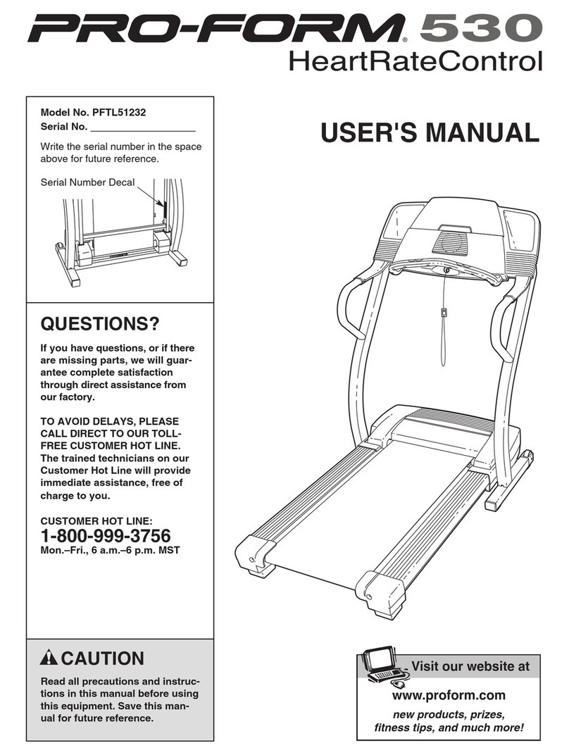
USER'S MANUAL
®
Serial
Number
Decal
Model No. PCTL62590
Serial No.
QUESTIONS?
As a anufacturer, we are co -
itted to providing co plete
custo er satisfaction. If you
have questions, or if there are
issing parts, please call:
1-888-936-4266
Mon.–Fri. 8h00 until 18h30 EST
(excluding holidays).
CAUTION
Read all precautions and instruc-
tions in this anual before using
this equip ent. Save this anual
for future reference.
www.profor .co
Visit our website at
2
TABLE OF CONTENTS
IMPORTANT PRECAUTIONS . . . . . . . . . . . . . . . . . . . . . . . . . . . . . . . . . . . . . . . . . . . . . . . . . . . . . . . . . . . . . . . . .2
BEFORE YOU BEGIN . . . . . . . . . . . . . . . . . . . . . . . . . . . . . . . . . . . . . . . . . . . . . . . . . . . . . . . . . . . . . . . . . . . . . . .4
ASSEMB Y . . . . . . . . . . . . . . . . . . . . . . . . . . . . . . . . . . . . . . . . . . . . . . . . . . . . . . . . . . . . . . . . . . . . . . . . . . . . . . .5
OPERATION AND ADJUSTMENT . . . . . . . . . . . . . . . . . . . . . . . . . . . . . . . . . . . . . . . . . . . . . . . . . . . . . . . . . . . . .7
HOW TO FO D AND MOVE THE TREADMI . . . . . . . . . . . . . . . . . . . . . . . . . . . . . . . . . . . . . . . . . . . . . . . . . .11
MAINTENANCE AND TROUB E-SHOOTING . . . . . . . . . . . . . . . . . . . . . . . . . . . . . . . . . . . . . . . . . . . . . . . . . . .12
CONDITIONING GUIDE INES . . . . . . . . . . . . . . . . . . . . . . . . . . . . . . . . . . . . . . . . . . . . . . . . . . . . . . . . . . . . . . .14
ORDERING REP ACEMENT PARTS . . . . . . . . . . . . . . . . . . . . . . . . . . . . . . . . . . . . . . . . . . . . . . . . . . . . . . . . . .15
IMITED WARRANTY . . . . . . . . . . . . . . . . . . . . . . . . . . . . . . . . . . . . . . . . . . . . . . . . . . . . . . . . . . . . . . .Back Cover
Note: An EXP ODED DRAWING and PART IST are attached in the center of this manual. Save them for future
reference.
1. It is the responsibility of the owner to ensure
that all users of this tread ill are adequately
infor ed of all warnings and precautions.
2. Use the tread ill only as described in this
anual.
3. Place the tread ill on a level surface, with at
least 2 (8 ft.) of clearance behind it. Do not
place the tread ill on any surface that blocks
air openings. To protect the floor or carpet
fro da age, place a at under the tread ill.
4. Keep the tread ill indoors, away fro ois-
ture and dust. Do not put the tread ill in a
garage or covered patio, or near water.
5. Do not operate the tread ill where aerosol
products are used or where oxygen is being
ad inistered.
6. Keep children under the age of 12 and pets
away fro the tread ill at all ti es.
7. The tread ill should not be used by persons
weighing ore than 115 kg (250 lbs.).
8. Never allow ore than one person on the
tread ill at a ti e.
9. Wear appropriate exercise clothing when
using the tread ill. Do not wear loose cloth-
ing that could beco e caught in the tread ill.
Athletic support clothes are reco ended for
both en and wo en. Always wear athletic
shoes. Never use the treadmill with bare feet,
wearing only stockings, or in sandals.
10. When connecting the power cord (see page 8),
plug the power cord into a surge suppressor
(not included) and plug the surge suppressor
into a grounded circuit capable of carrying 15
or ore a ps. No other appliance should be on
the sa e circuit. Do not use an extension cord.
11. Use only a CUL-listed surge suppressor of 450
joules ini u surge dissipation with voltage
rating of 400 volts or less, rated at 15 a ps,
with a (1 2)14-gauge cord of 1,5 (5 ft.) or
less in length. Do not use an extension cord.
12. Keep the power cord and the surge suppres-
sor away fro heated surfaces.
13. Never ove the walking belt while the power
is turned off. Do not operate the tread ill if
the power cord or plug is da aged, or if the
tread ill is not working properly. (See
BEFORE YOU BEGIN on page 4 if the tread-
ill is not working properly.)
WARNING:To reduce the risk of burns, fire, electric shock, or injury to persons, read the
following i portant precautions and infor ation before operating the tread ill.
IMPORTANT PRECAUTIONS
3
14. Never start the tread ill while you are stand-
ing on the walking belt. Always hold the
handrails while using the tread ill.
15. The tread ill is capable of high speeds.
Adjust the speed in s all incre ents to avoid
sudden ju ps in speed.
16. The pulse sensor is not a edical device.
Various factors, including the user's ove-
ent, ay affect the accuracy of heart rate
readings. The pulse sensor is intended only
as an exercise aid in deter ining heart rate
trends in general.
17. To reduce the possibility of the tread ill over-
heating, do not operate the tread ill continu-
ously for longer than 1 hour.
18. Never leave the tread ill unattended while it
is running. Always re ove the key, unplug
the power cord and ove the on/off switch to
the off position when the tread ill is not in
use. (See the drawing on page 4 for the loca-
tion of the on/off switch.)
19. Do not atte pt to raise, lower, or ove the
tread ill until it is properly asse bled. (See
ASSEMBLY on page 5, and HOW TO FOLD
AND MOVE THE TREADMILL on page 11.)
You ust be able to safely lift 20 kg (45 lbs.)
in order to raise, lower, or ove the tread ill.
20. Do not change the incline of the tread ill by
placing objects under the tread ill.
21. When folding or oving the tread ill, ake
sure that the storage latch is fully closed.
22. Inspect and tighten all parts of the tread ill
regularly.
23. Never drop or insert any object into any
opening.
24. DANGER:Always unplug the power
cord i ediately after use, before cleaning
the tread ill, and before perfor ing the ain-
tenance and adjust ent procedures de-
scribed in this anual. Never re ove the
otor hood unless instructed to do so by an
authorized service representative. Servicing
other than the procedures in this anual
should be perfor ed by an authorized service
representative only.
25. This tread ill is intended for in-ho e use
only. Do not use this tread ill in any co er-
cial, rental, or institutional setting.
WARNING:Before beginning this or any exercise progra , consult your physician. This
is especially i portant for persons over the age of 35 or persons with pre-existing health proble s.
Read all instructions before using. ICON assu es no responsibility for personal injury or property
da age sustained by or through the use of this product.
SAVE THESE INSTRUCTIONS
The decal shown has been placed on your tread ill. If the decal is
issing, or if it is not legible, please call our Custo er Service
Depart ent, toll-free, to order a free replace ent decal (see ORDERING
REPLACEMENT PARTS on the back cover of this anual). Apply the
decal in the location shown.
4
Thank you for selecting the PROFORM®625EX tread-
mill. The 625EX treadmill combines advanced technol-
ogy with innovative design to let you enjoy an excellent
form of cardiovascular exercise in the convenience and
privacy of your home. And when you’re not exercising,
the unique 625EX can be folded up, requiring less than
half the floor space of other treadmills.
For your benefit, read this anual carefully before
using the tread ill. If you have additional questions,
please call our Customer Service Department toll-free
at 1-888-936-4266, Monday through Friday, 8h00 until
18h00 Eastern Time (excluding holidays). To help us
assist you, please note the product model number and
serial number before calling. The model number of the
treadmill is PCT 62590. The serial number can be
found on a decal attached to the treadmill (see the
front cover of this manual for the location).
Before reading further, please review the drawing
below and familiarize yourself with the labeled parts.
BEFORE YOU BEGIN
Handrail
Handrail
Console
Storage atch
Book Holder
Key/Clip
Circuit
Breaker
On/Off Switch
Walking Belt
Front
Wheel
Foot Rails
Power Cord
Rear Roller
Adjustment Bolts
Water Bottle
Holder (Bottle
not included)
Accessory Tray
RIGHT SIDE
LEFT SIDE
5
1. With the help of a second person, carefully raise the
treadmill to the upright position. While a second person
tips the treadmill to one side slightly and holds it, insert
one of the Extension egs (59) into the base of the
Uprights (32) as shown. Make sure that the Extension
eg is turned so the bracket is on top. Using the Allen
Wrench (102), tighten one of the two Extension eg
Screws (57) into the Base and the Extension eg. Next,
tip the treadmill to the other side and attach the other
Extension eg in the same way.
With the help of a second person, carefully lower the
treadmill so that both Extension egs (59) are resting
flat on the floor.
57
102
59
32
Bracket
1
2. Refer to HOW TO OWER THE TREADMI FOR
USE on page 11. Follow the instructions in step 2 to
lower the treadmill.
Without removing the tape from the atch (34), hold the
atch against the left Upright (32) as shown. Attach the
atch to the left Upright with four Catch Screws (33).
Make sure that the Screws are tight, but do not
overtighten the ; if the Screws are overtightened,
the Latch will not slide s oothly. After the atch is
attached, remove any visible tape.
Note: The inset drawing shows how the parts of the
atch (34) fit together.
34
33
33
32
2
ASSEMBLY
Asse bly requires two people. Set the treadmill in a cleared area and remove all packing materials. Do not dis-
pose of the packing materials until assembly is completed. Asse bly requires the included allen wrench
and your own phillips screwdriver , adjustable wrench , and scissors .
Spacer
Springs
Bracket atch
3. Cut the plastic tie holding the cage nut in the upper end
of the eft Handrail (60).
Position the eft Handrail (60) on the left Upright (32) as
shown. The bracket on the Extension eg (59) should
be inside of the lower end of the eft Handrail. Thread
a Handrail Bolt (30) with a Handrail Washer (31) into the
left Upright and the eft Handrail. Do not tighten the
Handrail Bolt yet.
60
30 31
32
59
3
6
62
59
59 33
33
60
6
102
101
32
6. Refer to HOW TO FO D THE TREADMI FOR
STORAGE on page 11. Follow the instructions in step 2
to fold the treadmill.
Attach the lower end of the Right Handrail (62) to the
right Extension eg (59) with a atch Screw (33). Attach
the lower end of the eft Handrail (60) in the same way.
Tighten all parts used in steps 3, 4, 5 and 6.
7. Remove the backing from the Adhesive Clip (101).
Press the Adhesive Clip onto the base of the right
Upright (32) as shown. Press the Allen Wrench (102)
into the Adhesive Clip.
8. Make sure that all parts are tightened before you
use the tread ill. To protect the floor or carpet, place
a mat under the treadmill.
7
5. Make sure that the Console Base (46) is on the
Handrails (60, 62). Route the Console Wire Harness
(90) up into the Console Base as shown. Insert any
slack into the Right Handrail (62).
Attach the Console Base (46) to the Handrails (60, 62)
with four Handrail Mounting Screws (24).
90
62
60
46
24
24
5
4. Cut the indicated plastic tie off the Right Handrail (62).
Feed the large wire tie and the Console Wire Harness (90)
into the Right Handrail and out through the indicated
bracket. Pull as much of the Console Wire Harness through
the Right Handrail as possible. Note: It may be helpful to
turn the Console over on a flat surface as you do this.
Next, rest the left side of the Console Base (46) on the
eft Handrail (not shown). While a second person holds
the Console Base and the Right Handrail (62) in the posi-
tion shown, cut the plastic tie holding the Wire Harness
(35) in the right Upright (32). Note: Be careful not to
drop the Wire Harness into the right Upright.
Next, connect the Wire Harness (35) to the Console Wire
Harness (90) (refer to the inset drawing). The latch on the
Wire Harness should snap onto the Console Wire
Harness. If the Wire Harnesses do not fit together eas-
ily, turn the ; do not force the together. Remove the
large wire tie from the Console Wire Harness and insert
the slack Wire Harness into the Right Upright (32).
Refer to step 3 on page 5 and attach the Right Handrail
(62) as described. Be careful to avoid da aging the
wires in the Right Handrail.
62
90
46
35
32
Bracket
Plastic
Tie
Plastic
Tie
Wire
Tie
490
35
7
THE PERFORMANT LUBETM WALKING BELT
Your treadmill features a walking belt coated with
PERFORMANT UBETM, a high-performance lubricant.
IMPORTANT: Never apply silicone spray or other
substances to the walking belt or the walking plat-
for . Such substances will deteriorate the walking
belt and cause excessive wear.
HOW TO PLUG IN THE POWER CORD
Your treadmill, like any other type of sophisticated
electronic equipment, can be seriously damaged by
sudden voltage changes in your home’s power.
Voltage surges, spikes, and noise interference can
result from weather conditions or from other appliances
being turned on or off.
To decrease the possi-
bility of your tread ill
being da aged, always
use a surge suppres-
sor with your tread ill
(see drawing 1 at the
right).
Surge suppressors are
sold at most hardware
stores and department
stores. Use only a CU -
listed surge suppressor
with 450 joules minimum
surge dissipation rated at
15 amps, with a 1mm2
(14-gauge) cord of five
feet or less in length.
This product ust be
grounded. If it should
malfunction or break
down, grounding pro-
vides a path of least resistance for electric current to
reduce the risk of electric shock. This product is
equipped with a cord having an equipment-grounding
conductor and a grounding plug. Plug the power cord
into a surge suppressor, and plug the surge sup-
pressor into an appropriate outlet that is properly
installed and grounded in accordance with all local
codes and ordinances.
This product is for use on a nominal 120-volt circuit,
and has a grounding plug that looks like the plug illus-
trated in drawing 1 below. A temporary adapter that
looks like the adapter illustrated in drawing 2 may be
used to connect the surge suppressor to a 2-pole
receptacle as shown in drawing 2 if a properly
grounded outlet is not available.
The temporary adapter should be used only until a
properly grounded outlet (drawing 1) can be installed
by a qualified electrician.
The green-colored rigid ear, lug, or the like extending
from the adapter must be connected to a permanent
ground such as a properly grounded outlet box cover.
Whenever the adapter is used it must be held in place
by a metal screw. So e 2-pole receptacle outlet box
covers are not grounded. Contact a qualified elec-
trician to deter ine if the outlet box cover is
grounded before using an adapter.
DANGER:I proper connection
of the equip ent-grounding conductor can
result in an increased risk of electric shock.
Check with a qualified electrician or service-
an if you are in doubt as to whether the
product is properly grounded. Do not odify
the plug provided with the product—if it will
not fit the outlet, have a proper outlet
installed by a qualified electrician.
1
2
Grounded Outlet Box
Grounded Outlet Box
Grounding Plug
Treadmill Power Cord
Grounding Plug
Grounding Plug
Grounding Pin
Surge Suppressor
Grounding Pin
Grounding Pin
Adapter
ug
Metal Screw
Grounded Outlet
OPERATION AND ADJUSTMENT
8
Clip
Key
Displays ED Track
Program Indicators
Manual Indicator
Incline Display
STEP-BY-STEP CONSOLE OPERATION
The console features a manual mode and four workout
programs. When the manual mode is selected, the
speed and incline of the treadmill can be changed with
a touch of a button. As you exercise, the ED track and
the four displays will provide continuous exercise feed-
back—you can even measure your heart rate with the
built-in pulse sensor. When one of the workout pro-
grams is selected, the console will automatically control
the speed as it guides you through an effective workout.
Before operating the
console, make sure that
the on/off switch near
the power cord is in the
on position.
Next, make sure that the key is removed from the con-
sole, and plug in the power cord (see HOW TO P UG
IN THE POWER CORD on page 7). Note: If the key
is in the console when the power cord is plugged
in, the letters “PO” will flash in the SPEED display.
If this occurs, re ove the key.
Step onto the foot rails of the treadmill. Find the clip
attached to the key (see the drawing above), and slide
the clip onto the waistband of your clothing.
Follow the steps below to operate the console. Note: If
there is a thin sheet of clear plastic on the face of the
console, remove it.
Insert the key fully
into the console.
When the key is in-
serted, various indica-
tors and displays on
the console will light.
Press the MODE button to select the desired
ode.
When the key is in-
serted, the manual
mode will be selected
and the MANUA indi-
cator will be lit. Note: If
a workout program has
been selected, press the MODE button repeatedly
to select the manual mode.
If you want to select one of the four workout pro-
grams, press the MODE button. The upper pro-
gram indicator will light. To select one of the other
three programs, press the MODE button repeatedly.
2
1
CAUTION:Before operating the
console, read the following precautions.
• Do not stand on the walking belt when turn-
ing on the power.
• Always wear the clip while operating the
tread ill.
• Adjust the speed in s all incre ents.
• To reduce the possibility of electric shock, keep
the console dry. Avoid spilling liquids on the
console, and use only a sealed water bottle.
On
Position
Pulse Sensor
Note: There are two twenty-minute programs and
two thirty-minute programs. The graphs on the left
side of the console show how the speed of the
walking belt will change during the programs.
During the program 1, for example, the speed will
gradually increase during the first ten minutes, and
then gradually decrease during the last ten min-
utes. Each program begins with a warm-up period
and ends with a cool-down period.
If a workout progra is selected, set a axi u
speed setting.
If the anual ode is selected, go to step 4.
If a workout progra is selected, a number will be
flashing in the SPEED display. This number is the
maximum speed that
the walking belt will
reach during the se-
lected program. If de-
sired, press the SPEED
▲▲
button repeatedly to
change the maximum
speed setting. If the maximum speed setting is in-
creased, the difficulty level of the entire program will
increase. If the maximum speed setting is de-
creased, the difficulty level of the entire program will
decrease.
Press the START/STOP button.
A moment after the
START/STOP button is
pressed, the walking
belt will begin to move.
Hold the handrails and
carefully begin walking.
If the anual ode is selected: As you exercise,
change the speed of the walking belt as desired by
pressing the SPEED buttons.
To stop the walking belt, press the START/STOP
button. The TIME/PACE display will begin to flash.
To restart the walking belt, press the START/STOP
button again. To stop the walking belt and reset the
displays, press the START/STOP button, remove
the key from the console, and then reinsert the key.
If a workout progra is selected: The speed of
the walking belt will change automatically during the
program as shown by the graphs on the left side of
the console. The time remaining in the program will
be shown in the TIME display. During the last few
seconds of each one-minute period of the program,
four tones will sound to alert you that the speed may
change. When the program is completed, the walk-
ing belt will slow to a stop.
Note: If the program is too difficult or too easy, the
difficulty level of the program can be adjusted. Press
the SPEED
▲▲
or
▼▼
button. A number will begin to
flash in the SPEED display. This number is the maxi-
mum speed that the walking belt will reach during
the program. Press the SPEED
▲▲
or
▼▼
button repeat-
edly to change the maximum speed setting. If the
maximum speed setting is increased, the difficulty
level of the entire program will increase. If the maxi-
mum speed setting is decreased, the difficulty level
of the entire program will decrease.
To stop the program for a moment, press the
START/STOP button. The TIME/PACE display will
begin to flash. To restart the program, press the
START/STOP button again. To stop the program
and reset the displays, press the START/STOP
button, remove the key from the console, and then
reinsert the key.
Change the incline of the tread ill, if desired.
To change the incline,
press the INC INE
buttons. Each time
one of the buttons is
pressed, the incline
will change by 0.5%.
Every three times a
button is pressed, one
additional indicator will
light or darken in the
incline display. The
buttons can be held
down to change the in-
cline quickly. Note:
After the buttons are
pressed, it may take a
moment for the treadmill to reach the selected in-
cline setting.
Follow your progress with the LED track and the
four displays.
The LED
Track—The
ED track repre-
sents a distance
of 1/4 mile. As
you exercise, the
indicators
around the track
will light one at a time until you have completed 1/4
mile. The indicators will then darken and another lap
will begin.
6
5
4
3
9
10
• DISTANCE/ APS
display—This display
shows the total dis-
tance that you have
walked and the num-
ber of laps you have
completed (one lap equals 1/4 mile). The display
will alternate between one number and the other
every seven seconds. The APS indicator will
light when the number of laps is shown.
• TIME/PACE dis-
play—This display
shows the elapsed
time and your current
pace (pace is mea-
sured in minutes per
mile). The display will alternate between one
number and the other every seven seconds. The
PACE indicator will light when your pace is
shown. Note: When a workout program is se-
lected, the display will show the time remaining in
the program.
• SPEED display—
This display shows
the speed of the
walking belt, in miles
per hour or kilome-
ters per hour. The
KPH indicator will light when the speed is shown
in kilometers per hour.
To change the unit of measurement, hold down
the START/STOP button while inserting the key
into the console. An “E” for “English” (miles per
hour) or an “M” for “Metric” (kilometers per hour)
will appear in the CA S/FAT CA S/PU SE dis-
play. Press the SPEED
▲▲
button to change the
unit of measurement. Remove and then reinsert
the key.
• CA S/FAT CA S/
PU SE display—
This display shows
the approximate
numbers of calories
and fat calories you
have burned (see FAT BURNING on page 14).
Every seven seconds, the display will change
from one number to the other. The FAT indicator
will light when the number of fat calories is
shown. Note: This display will also show your
heart rate when the pulse sensor is used (see
step 7).
Measure your heart rate, if desired.
Stand on the
foot rails and
place your
thumb on the
pulse sensor as
shown. The
pulse sensor is
pressure-acti-
vated—fully press
it down. (Do not
press too hard,
or the circulation
in your thu b
will be restricted, and your pulse will not be de-
tected.) Next, raise your thumb slightly until the
heart-shaped indicator by the CA S/FAT CA S/
PU SE display flashes steadily and a “P” appears
in the display. Hold your thumb at this level. After a
few seconds, three dashes will appear in the dis-
play and then your heart rate will be shown. Hold
your thumb on the sensor for another 15 seconds
for the most accurate reading.
If the displayed heart rate appears to be too high
or too low, or if your heart rate is not displayed, lift
your thumb and allow the display to reset. Press
down again on the sensor as described above.
Make sure that your thumb is positioned as shown,
and that you are applying the proper amount of
pressure. Try the sensor several times until you
become familiar with it. Remember to stand still
while measuring your pulse.
When you are finished, re ove the key.
Step onto the foot rails and remove the key from
the console. Store the key in a secure place. In ad-
dition, move the on/off switch to the off position.
(See the drawing near the bottom of page 8.)
THE INFORMATION MODE
To access the console’s information mode, hold down
the START/STOP button while inserting the key into the
console. An “E” for “English” (miles per hour) or an “M”
for “Metric” (kilometers per hour) will appear in the
CA S/FAT CA S/PU SE display. Pressing the SPEED
▲▲
button will change the unit of measurement. The
TIME/PACE display will show the total number of hours
the treadmill has been used. The SPEED display will
show the total number of miles accumulated on the
treadmill. To exit the information mode, remove the key
from the console.
8
7
Pulse Sensor
Indicator