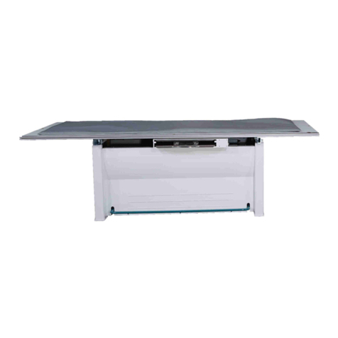
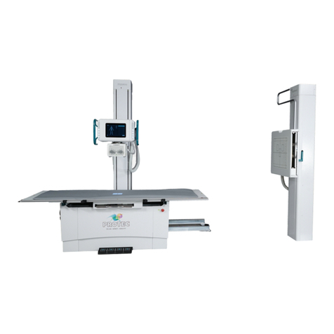
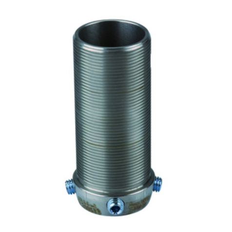
Pro-tec 7073-9-000 Series User manual

PROTEC GmbH & Co. KG
In den Dorfwiesen 14, 71720 Oberstenfeld, Germany
Version: 5.0
Issued: 2021-11-24
Subject to alterations
PROGNOST C
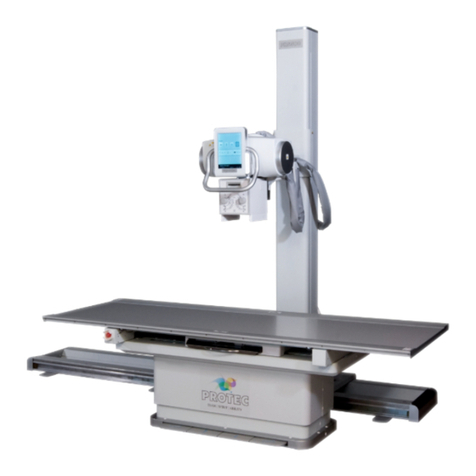
Diagnostic X-ray system mechanics
odel/ID: 7073-9-000X
Basis-UDI-DI: 426050264X013ZJ
Instructions for use
Ident. No. 5073-0-0002

NOTE
All sheets of this document contain proprietary and confidential information of
PROTEC GmbH & Co. KG and is intended for exclusive use by current PROTEC GmbH
& Co. KG customers. Copying, disclosure to other or other use is prohibited without
the express written authorization of PROTEC´s law department. Report any
violations of this requirement to PROTEC GmbH & Co. KG.
© 2021 PROTEC GmbH & Co. KG, Oberstenfeld
These accompanying documents were created and distributed by the documentation department.
Comments and questions about the documentation, please contact:
PROTEC GmbH & Co. KG
In den Dorfwiesen 14 | 71720 Oberstenfeld
Germany
Phone: (+ 49) 7062 – 92 55 0
Fax: (+ 49) 7062 – 92 55 60
E- ail: protec@protec-med.com
Internet: www.protec-med.com

V5.0_2021-11-24 PROGNOST C
Instructions for use 5073-0-0002
PROTEC GmbH & Co. KG, In den Dorfwiesen 14, 71720 Oberstenfeld, Germany 3 von 31
Table of contents
Page
Table of contents ........................................................................................................................... 3
Revision Status .............................................................................................................................. 5
General Notes ................................................................................................................................ 6
echanical – Electric Warning .................................................................................................... 6
To the User ..................................................................................................................................... 6
1
Product description ............................................................................................................ 7
1.1 Introduction ......................................................................................................................................................................................... 7
1.2 Description............................................................................................................................................................................................ 7
1.2.1 Models ......................................................................................................................................................................................... 7
1.2.2 Hardware and Network System Requirements ................................................................................................. 7
1.2.3 Installation ................................................................................................................................................................................ 8
1.2.3.1 Floor loading capacity ................................................................................................................................................. 8
1.3 Performance characteristics ....................................................................................................................................................... 8
1.3.1 Patient positioning table ................................................................................................................................................. 8
1.3.2 Floor-guided tube column stand ............................................................................................................................... 8
1.3.3 Vertical Bucky Wall Stand ................................................................................................................................................
1.4 Intended Use .......................................................................................................................................................................................
1.5 Clinical Benefit ....................................................................................................................................................................................
1.6 Patient Target Group(s) .................................................................................................................................................................
1.7 Medical Conditions to be diagnosed ...................................................................................................................................
1.8 Indications and Contraindications .........................................................................................................................................
1. Intended Operator Group ...........................................................................................................................................................
1.10 Declaration of Conformity ........................................................................................................................................................ 10
2
Safety Instructions ............................................................................................................ 11
2.1 General safety instructions ....................................................................................................................................................... 12
2.1.1 Requirements for operation ....................................................................................................................................... 12
2.1.2 Device Operation .............................................................................................................................................................. 12
2.1.2.1 Operating Type ............................................................................................................................................................ 12
2.1.3 Operating Personnel ....................................................................................................................................................... 12
2.1.4 Crushing and Collision Hazard .................................................................................................................................. 12
2.1.5 Explosion Protection ....................................................................................................................................................... 13
2.1.6 Interaction with Other Devices ................................................................................................................................. 13
2.1.7 Electromagnetic Environment and Influencing of Devices .................................................................... 13
3
Control Elements and Displays ....................................................................................... 14
3.1 Main Switch of the PROGNOST C ........................................................................................................................................ 14
3.2 Emergency Stop Switch of the PROGNOST C .............................................................................................................. 14
3.3 Floor-guided tube column stand ........................................................................................................................................ 14
3.4 Patient positioning table ........................................................................................................................................................... 15
3.5 Vertical Bucky Wall Stand .......................................................................................................................................................... 15
4
Handling ............................................................................................................................. 16
4.1 Requirements before and during Operation ................................................................................................................ 16
4.2 Operation of the PROGNOST C ............................................................................................................................................. 16
4.2.1 Releasing the table top brake (positioning the table top) ....................................................................... 16
4.2.2 Positioning the image receptor from the wall stand .................................................................................. 16
4.2.3 Exposures with mechanics for basic diagnostic X-ray systems ............................................................ 16
4.2.3.1 Positioning/descending of the patient on/from the table top ...................................................... 16
4.2.3.2 Setting the X-ray unit on the centre of the Bucky, Grid Entity ........................................................ 16
4.2.3.3 Inserting a cassette into the cassette tray .................................................................................................... 16
4.2.3.4 Adjustment of the focus-film distance (SID) .............................................................................................. 16
4.2.3.5 Adjusting the light-/beam field.......................................................................................................................... 16
4.2.3.6 Exposure preparation / Exposure releasing ................................................................................................ 17
4.2.3.7 Exposure with cassette on the table top ...................................................................................................... 17

V5.0_2021-11-24 PROGNOST C
Instructions for use 5073-0-0002
PROTEC GmbH & Co. KG, In den Dorfwiesen 14, 71720 Oberstenfeld, Germany 4 von 31
4.2.4 Operation at the wall stand ........................................................................................................................................ 17
4.2.4.1 Adjustment of the X-ray unit to the centre of a cassette or Bucky/Grid Entity of an X-ray
system wall stand (vertical centre beam) ........................................................................................................................... 17
4.2.4.2 Adjustment of image-receptor distance (SID) .......................................................................................... 17
4.2.4.3 Adjustment of the light-/ radiation field....................................................................................................... 17
4.2.4.4 Exposure preparation/ Exposure release ...................................................................................................... 17
4.3 Function of the PROGNOST C ................................................................................................................................................ 17
4.3.1 Switching the PRS 500 C on and off ...................................................................................................................... 17
5
Safety and aintenance ................................................................................................... 19
5.1 Introduction ...................................................................................................................................................................................... 1
5.2 Reusability .......................................................................................................................................................................................... 1
5.3 Cleaning and Disinfection ........................................................................................................................................................ 1
5.3.1 Cleaning .................................................................................................................................................................................. 1
5.3.2 Disinfection ........................................................................................................................................................................... 1
5.4 Inspection and maintenance ................................................................................................................................................. 20
5.4.1 Daily monitoring before and during investigation Operation .............................................................. 20
5.4.2 Regular Monitoring .......................................................................................................................................................... 20
5.4.2.1 Quality control by the user.................................................................................................................................... 20
5.4.3 Maintenance ........................................................................................................................................................................ 20
5.4.4 Warranty .................................................................................................................................................................................. 21
5.4.5 Product Service Life ......................................................................................................................................................... 21
5.4.6 Further Information ......................................................................................................................................................... 21
5.4.7 Applied Parts and Parts Considered as Applied Parts ................................................................................. 21
5.4.8 Disposal ................................................................................................................................................................................... 21
6
Electrical data ..................................................................................................................... 22
6.1 Electromagnetic Compatibility (EMC) according to EN 60601-1-2 ................................................................ 22
6.1.1 Guidelines and Manufacturers Declaration – Electromagnetic Interference ............................... 22
7
Technical Data .................................................................................................................... 25
7.1 Dimensions ........................................................................................................................................................................................ 25
7.2 Patient positioning table ........................................................................................................................................................... 27
7.3 Bucky unit ........................................................................................................................................................................................... 27
7.4 X-ray stem tube support, floor stand ................................................................................................................................. 27
7.5 Vertical X-ray system image receptor stand .................................................................................................................. 27
7.6 Attenuation Equivalent .............................................................................................................................................................. 28
7.6.1 Protection Art and Protection Class ....................................................................................................................... 28
7.7 Environmental ................................................................................................................................................................................. 28
7.7.1 Environmental conditions during operation ................................................................................................... 28
7.7.2 Environmental conditions for shipping and storage .................................................................................. 28
8
Description of symbols, labels and abbreviations ....................................................... 29
8.1 Symbols ............................................................................................................................................................................................... 2
8.2 Type label ........................................................................................................................................................................................... 30
8.3 Labels .................................................................................................................................................................................................... 30
8.4 Position of the signs and labels ............................................................................................................................................ 31
8.5 Abbreviations ................................................................................................................................................................................... 31

V5.0_2021-11-24 PROGNOST C
Instructions for use 5073-0-0002
PROTEC GmbH & Co. KG, In den Dorfwiesen 14, 71720 Oberstenfeld, Germany 5 von 31
NOTE
The information contained in this document conforms to the configuration of the
equipment as of the date of manufacture. Revisions to the equipment subsequent
to the date of manufacture will be addressed in service updates distributed to the
PROTEC Technical Service Organization.
Revision Status
Revision
No. Date List of effective
pages Comments Author
1.0 2020-11-26 all Original issue
2.0 2021-02-25 Front Page, 7, 11,
14, 15, 18, 23, 27
Product picture, Warning mattress,
Compatible components, mattress
at characteristic table added,
symbols and labels, cleaning,
mattress added to technical data
table
3.0 2021-03-11
7, 8, 18, 1 , 20,
21, 23, 24, 25, 26,
27
X-ray mattress description,
compatible components, note X-ray
mattress at characteristic table,
cleaning, disinfection, lifetime,
applied parts, symbols and labels,
chapter power supply connection,
X-ray mattress changed at technical
data table, note attenuation
equivalent
4.0 2021-05-26 all V3.0 transferred to new layout
(MDR)
MB
5.0 2021-11-24
8, 10, 15-1 , 21,
26-32
X-ray mattress removed, front page
changed, Chap. 1 product
description revised, chap. 3 control
elements & device displays revised,
chap. 4 Handling revised, chap. 5
safety maintenance revised, chap. 7
technical data revised, chap. 8
description of symbols & labels
revised
MB

V5.0_2021-11-24 PROGNOST C
Instructions for use 5073-0-0002
PROTEC GmbH & Co. KG, In den Dorfwiesen 14, 71720 Oberstenfeld, Germany 6 von 31
General Notes
WARNING!
In order to maintain the set and tested requirements of the 60601 series of
standards, the E system must not be modified during its actual operating
life.
echanical – Electric Warning
WARNING!
All of the movable assemblies and parts of this equipment should be operated
with care and routinely inspected in accordance with the manufacturer's
recommendations contained in the equipment accompanying documents.
aintenance and service is only to be performed by customers authorized by
PROTEC GmbH & Co. KG.
Live electrical terminals are deadly.
Do not remove flexible high-tension cables from X-ray tube cover or high-
tension generator and/or access covers from X-ray generator.
For all components of the equipment protective earthing means must be
provided in compliance with the national regulations.
Failure to comply with the foregoing may result in serious or fatal bodily
injuries to the operator or those in the area.
To the User
NOTE
The user of these accompanying documents is required to carefully read through
and carefully consider the instructions, warnings and cautions contained therein
before starting operation.
Even if you have already operated similar systems, changes in the design,
production and functional routine of the system described here may have been
made, which have a significant influence on the operation.
Assembly and service works on the system described here must be carried out by
authorised and qualified personnel from PROTEC GmbH & Co. KG. Assembly
personnel and other persons who are not employees of the technical service
department of PROTEC GmbH & Co. KG are requested to contact the local branch of
PROTEC GmbH & Co. KG before assembly or service work is started.
For assembly and service works, it is necessary to use the "Technical Description” of
the product and to observe the points it contains.
NOTE
The usage of the product in combination with accessories not authorized by
PROTEC is forbidden.
NOTE
According to Regulation (EU) 2017/745 of medical devices, all serious incidents
related to the device must be reported to the manufacturer and the responsible
authority of the Member State where the user and/or the patient is established.

V5.0_2021-11-24 PROGNOST C
Instructions for use 5073-0-0002
PROTEC GmbH & Co. KG, In den Dorfwiesen 14, 71720 Oberstenfeld, Germany 7 von 31
1
Product description
1.1 Introduction
The instructions for use describe the performance characteristics and operation required for efficient
and effective use of the PROGNOST C.
Before you work with the PROGNOST C, the complete instructions for use must be read, especially the
Safety Instructions and the chapter Handling.
1.2 Description
The mechanics for basic diagnostic X-ray systems PROGNOST C is constituted of a stationary patient
positioning table with floating table top, a floor-guided tube column stand and a vertical Bucky wall
stand (without X-ray components).
The floating table top can be locked in a longitudinal and transverse direction by using an
electromagnetic brake. The brake is controlled by a light barrier.
The table is prepared for the installation of a longitudinally sliding Bucky or Grid entity, an anti-scatter
grid and a measuring chamber intended for use with an automatic exposure control.
The tube column stand is guided by one rail, which is fixed on the ground behind the table. All
movements of the column stand are smooth and locked by electromagnetic brakes. The weight-
balanced support arm is prepared for the installation of an X-ray tube assembly (X-ray tube, collimator
and control panel with integrated controls).
1.2.1 odels
PROGNOST C 7073- -0001 Wall stand left
PROGNOST C 7073- -0002 Wall stand right
Optional Accessories
The PROGNOST C can be equipped or customized with the following accessories:
•Patient extending handle
Integrable components (stand-alone products) and possible combinations
These parts are not included in the scope of delivery of the PROGNOST C but can be combined it.
•Collimator
•X-ray tube assembly
•X-ray generator VENUS-series
•Measuring chamber
•Dose area product meter system
•Anti-scatter grid
•Different direct X-ray-systems (RAPIXX-series)
(consisting of DR-detector, Interface Box, and Software)
Accessories that can influence the E C conditions
•Network cable ((take note of the max. cable length in the system documents)
•RAPIXX data connection cable (take note of the max. cable length in the system documents)
•Wi-Fi router (only use devices approved by PROTEC)
•…
1.2.2 Hardware and Network System Requirements
As a stand-alone product, the PROGNOST C has no hardware or network connection and therefore no
hardware or network requirements.

V5.0_2021-11-24 PROGNOST C
Instructions for use 5073-0-0002
PROTEC GmbH & Co. KG, In den Dorfwiesen 14, 71720 Oberstenfeld, Germany 8 von 31
1.2.3 Installation
NOTE
The installation of the PROGNOST C must be performed by PROTEC service
department or a service company authorized by them.
For more information, please see separate Installation manual of the PROGNOST C.
Contact information of persons qualified to perform installations are available upon request at:
PROTEC GmbH & Co. KG
In den Dorfwiesen 14 | 71720 Oberstenfeld
Germany
Phone: (+ 4 ) 7062 – 2 55 0
Fax: (+ 4 ) 7062 – 2 55 60
E-Mail: protec@protec-med.com
Internet: www.protec-med.com
1.2.3.1 Floor loading capacity
NOTE
The PROGNOST C is primarily made of metal pieces. This has a main role in the
weight of the device.
The X-ray system PROGNOST C has a weight of 545kg.
Every technician is obliged to check the ground loading capacity. Also raised floors
and hollow floors must be taken into account.
1.3 Performance characteristics
1.3.1 Patient positioning table
•Floating table top
•Table top colour white
•Electromagnetic table top brake for effortless patient positioning
•A low optimized distance between the table top surface and the film (detector) surface
•Large adjustment range of the table top for position of the patient
•Reliable construction
•Prepared for the installation of a Bucky with anti-scatter grid and 3-field measuring chamber
intended for the use with automatic exposure control
•Useable for variable cassette/detector sizes. Formats from 13 cm x 18 cm (5” x 7”) to 43 cm x 43
cm (17” x 17”), depending on analogue or digital use.
1.3.2 Floor-guided tube column stand
•Ceiling-free column stand intended for use within rooms with a ceiling height of at least 2.20
meters
•Wide range of application
•Small wall distance allows good space utilization
•Control elements within the command arm are well placed and easy to activate
•Reproducible positioning of the X-ray tube assembly (positions resulting from rotation around
the axis of the carrying arm) through angle indicator
•Vertical range of travel of the focus height from 40.0 cm up to 176.5 cm during horizontal
beam projection

V5.0_2021-11-24 PROGNOST C
Instructions for use 5073-0-0002
PROTEC GmbH & Co. KG, In den Dorfwiesen 14, 71720 Oberstenfeld, Germany von 31
•Electromagnetic brakes for the longitudinal movement of the column stand, the vertical
movements of the carrying arm, the rotational movements of the X-ray tube assembly around
the axis of the carrying arm +/-135°.
•Integrated safety connector for automatically centring the X-ray tube assembly and the Bucky
in the longitudinal direction.
1.3.3 Vertical Bucky Wall Stand
•Space saving with minimal footprint
•Wall – floor mounting of floor mounting
•cassette loading from the right or left side (specified at installation)
•Useable for variable cassette/detector sizes. Formats from 13 cm x 18 cm (5” x 7”) to 43 cm x 43
cm (17” x 17”), depending on analogue or digital use.
1.4 Intended Use
The X-ray system mechanics PROGNOST C is designated as a component to be used for the assembly
of a diagnostic X-ray system for various routine applications in planar X-ray imaging in human
medicine.
1.5 Clinical Benefit
Considered in isolation, no clinical benefit can be shown for X-ray system mechanics.
As components of diagnostic X-ray systems in human medicine, they contribute to the clinical benefit
of X-ray systems, which consists of the generation of conventional two-dimensional X-ray images for
creation or specification of findings as a basis for treatment decisions.
1.6 Patient Target Group(s)
The intended patient group includes all people for whom a justifying indication for a medical X-ray has
been given by a physician with the necessary expertise in radiation protection.
There are no general or fundamental restrictions on the patient group regarding age, gender, origin
and patient condition.
1.7 edical Conditions to be diagnosed
As standalone products, X-ray system mechanics, have no function to diagnose, treat and/or monitor
medical conditions.
1.8 Indications and Contraindications
As standalone products, X-ray system mechanics have no intended main effect in or at the human
body. Therefore, considered in isolation, no indications and contraindications can be shown for them.
1.9 Intended Operator Group
As a component of a diagnostic X-ray system, PROGNOST C is intended exclusively for use by
professional users who are trained in the operation of diagnostic X-ray systems in accordance with the
respective national regulations and who are familiar with the proper handling, use and operation and
also have been instructed in the permitted conjunction with other medical products, objects and
accessories.
Appropriate users can be, for example: X-ray technicians, X-ray assistants, medical technical X-ray
assistants, surgeons, casualty surgeons, orthopaedists and other trained medical personnel.

V5.0_2021-11-24 PROGNOST C
Instructions for use 5073-0-0002
PROTEC GmbH & Co. KG, In den Dorfwiesen 14, 71720 Oberstenfeld, Germany 10 von 31
1.10 Declaration of Conformity
This product complies with the requirements of Regulation (EU) 2017/745 of the European
Parliament and of the Council of 5 April 2017 concerning medical devices, including all
applicable corrigenda.
The declaration of conformity is available upon request from PROTEC:
PROTEC GmbH & Co. KG
In den Dorfwiesen 14 | 71720 Oberstenfeld
Germany
Phone: (+ 4 ) 7062 – 2 55 0
Fax: (+ 4 ) 7062 – 2 55 60
E-Mail: protec@protec-med.com
Internet: www.protec-med.com

V5.0_2021-11-24 PROGNOST C
Instructions for use 5073-0-0002
PROTEC GmbH & Co. KG, In den Dorfwiesen 14, 71720 Oberstenfeld, Germany 11 von 31
2
Safety Instructions
NOTE
Contains information that must be observed during operation.
xxx
CAUTION!
Contains information which, if not observed, can cause property
damage.
xxx
WARNING!
Contains information which, if not followed, can cause personal
injury.
xxx
WARNING!
Warning of radioactive substances or ionizing radiation. Contains
information which, if not observed, can cause personal injury.
xxx
Settings and calibrations that are not described in these instructions for use must be carried out using
the technical description of the device by PROTEC service department or a service company authorized
by them.
NOTE
All instructions supplied with the PROGNOST C must be observed and the safety
instructions contained therein must be carefully read and adhered to.
NOTE
After the initial installation, the commissioning must be recorded with the PROTEC
acceptance protocol FB-04-07A4.
NOTE
The PROGNOST C may only be commissioned if all safety measures for operator
protection have been met and checked. These protective measures can include
door contact, designated area, dosimeter, protective clothing, etc.
CAUTION!
The instructions for use contain all the information relevant to safety in order
to generally put the PROGNOST C into operation. The device may only be
operated by appropriately trained and trained personnel. In this context,
operation is ensured by clear symbols on the control elements. All further
information and instructions can be found on the supplied data carrier (USB,
CD or DVD). This information applies in its entirety as an appendix to these
instructions for use and must be observed.

V5.0_2021-11-24 PROGNOST C
Instructions for use 5073-0-0002
PROTEC GmbH & Co. KG, In den Dorfwiesen 14, 71720 Oberstenfeld, Germany 12 von 31
NOTE
All control elements are described again in detail in these operating instructions.
2.1 General safety instructions
2.1.1 Requirements for operation
WARNING!
The PROGNOST C is a protection class I device (according to EN 60601-1).
To avoid the risk of an electric shock, this device may only be connected to a
supply network with a protective earthing conductor.
The power supply for the PROGNOST C of the X-ray system is exclusively made
by direct connection to the X-ray generator or the Power Box and is
permanently connected there. The X-ray generator or the Power Box must
have at least 2 connections for 230V 50/60Hz.
The X-ray generator of the X-ray system is connected to the supply network
(see technical description of the X-ray generator).
To reduce the risk of electric shock, the system must be connected to a supply
network with protective earthing.
The system does not have an on/off switch. It is switched on or off directly by
switching on the X-ray generator or by the switch on the Power Box. In order
to separate any electrical voltage from the X-ray system, the connected X-ray
generator or the Power Box must be switched off.
2.1.2 Device Operation
In case of a malfunction, do not use the PROGNOST C anymore and notify PROTEC service department
or a service company authorized by them.
2.1.2.1 Operating Type
The PROGNOST C is not intended for continuous operation.
2.1.3 Operating Personnel
NOTE
Only trained and authorized personnel are allowed to work on the PROGNOST C.
NOTE
The operating personnel must be familiar with all warning signs attached to the
PROGNOST C. They are used for your own safety and that of others and ensure
proper operation.
2.1.4 Crushing and Collision Hazard
WARNING!
It must be ensured that when operating the moving parts of PROGNOST C, no
persons or objects are in the obvious danger area of the device. If not
observed, it can result in personal injury or damage to the PROGNOST C or
other objects.

V5.0_2021-11-24 PROGNOST C
Instructions for use 5073-0-0002
PROTEC GmbH & Co. KG, In den Dorfwiesen 14, 71720 Oberstenfeld, Germany 13 von 31
2.1.5 Explosion Protection
These PROGNOST C is not designated for use within areas with explosive hazards.
2.1.6 Interaction with Other Devices
Interactions with other devices are not known.
2.1.7 Electromagnetic Environment and Influencing of Devices
CAUTION!
The use of other accessories, other converters and other cables than those
specified by PROTEC or provided in the documentation of the component
manufacturer can result in increased electromagnetic interference or reduced
electromagnetic immunity of the device and lead to defective operation.
CAUTION!
The use of the PROGNOST C immediately next to other devices or with other
devices in a stacked form should be avoided, as this could result in defective
operation. If use in the manner described above is nevertheless necessary, the
PROGNOST C and the other devices should be observed to ensure that they
are working properly.
NOTE
The properties of this device, determined by emissions, allow its use in industrial
areas and in hospitals (CISPR 11, class A). When used in residential areas (for which
class B is usually required by CISPR 11), this device may not provide adequate
protection for radio services. The user may need to take remedial measures such as
relocating or realigning the device.
The PROGNOST C is intended for use in an environment in professional health care facilities (e.g., clinics,
surgery centres, physiology practices ...).

V5.0_2021-11-24 PROGNOST C
Instructions for use 5073-0-0002
PROTEC GmbH & Co. KG, In den Dorfwiesen 14, 71720 Oberstenfeld, Germany 14 von 31
3
Control Elements and Displays
3.1 ain Switch of the PROGNOST C
The PROGNOST C is switched on and off via a button (on the backside of the patient table).
3.2 Emergency Stop Switch of the PROGNOST C
The PROGNOST C has no emergency stop switches, which can be used to bring the device to an
immediate standstill and disconnect it from the power supply.
3.3 Floor-guided tube column stand
Longitudinal movement tube column
Brake for the longitudinal/horizontal movement of the tube column
Tube head up/down
Brake for the height positioning /vertical movement of the tube head
Tube Rotation
Brake for the tube head rotation around the carrying axis
Free movement (sensor beneath the tube head)
Permits the horizontal movement of the tube column and vertical movement of the
tube head
Free
movement
Tube head
rotation
Tube head
rotation
Longitudinal movement
tube column
Up & down
movement tube
head

V5.0_2021-11-24 PROGNOST C
Instructions for use 5073-0-0002
PROTEC GmbH & Co. KG, In den Dorfwiesen 14, 71720 Oberstenfeld, Germany 15 von 31
3.4 Patient positioning table
CAUTION!
By activating the light barrier, the electromagnetic table top brakes are
supplied with power that they switch off and the table top can be moved. It
must be ensured that no objects are continuously laying in the light barrier
and permanently trigger it, otherwise the brakes are supplied with
continuous current and could get damaged.
3.5 Vertical Bucky Wall Stand
Brake for the vertical movement of the wall stand Bucky.
Up/down
release button
Light barrier to release the table top
brake (represented by the red line)
Power ON/OFF

V5.0_2021-11-24 PROGNOST C
Instructions for use 5073-0-0002
PROTEC GmbH & Co. KG, In den Dorfwiesen 14, 71720 Oberstenfeld, Germany 16 von 31
4
Handling
4.1 Requirements before and during Operation
It must be ensured that the surfaces in contact with patients are disinfected before the X-ray
examination of each patient (see chapter 5.3).
4.2 Operation of the PROGNOST C
4.2.1 Releasing the table top brake (positioning the table top)
By actuating the light barrier with the foot, the brakes of the table top are released, whereby the table
top can be moved floating by hand.
Prior to patient positioning, the X-ray unit must be brought into the required exposure
position.
4.2.2 Positioning the image receptor from the wall stand
By pressing the release button on the wall stand, the brakes for the grid device are released, the grid
device can be moved by hand.
4.2.3 Exposures with mechanics for basic diagnostic X-ray systems
4.2.3.1 Positioning/descending of the patient on/from the table top
•Move the table top to a position to make it easy for the patient to climb onto/from the table
surface.
•The patient should position himself in the middle of the table top and remain in this position.
4.2.3.2 Setting the X-ray unit on the centre of the Bucky, Grid Entity
•By pressing the button “longitudinal movement tube column” (see figure operating unit), release
the brake for the longitudinal movement.
•Grab both handles on both sides of the command arm.
•Move the X-ray tube assembly in the longitudinal direction along the radiographic X-ray table until
the Bucky/Grid Entity snaps into the safety coupling.
4.2.3.3 Inserting a cassette into the cassette tray
•A film cassette may be placed into the cassette tray, after the X-ray tube assembly is positioned.
•Pull out the cassette tray by its handle from the Bucky/Grid Entity unit until it hits the forward stop.
•Rotate the latch for opening/closing the clamping device, for lateral fixation of the cassette,
counter clockwise to unlock it.
•Open the cassette clamps far enough to insert a cassette of the desired size.
•Insert the cassette, aligning its centreline with the notch on the clamp, or after engaging the
cassette positioner in the notch corresponding to the cassette size (13 cm, 18 cm, 24 cm, 30 cm, 35
cm, 40 cm or 43 cm), push the cassette toward the cassette positioner.
•Push the cassette clamps against the cassette and rotate the latch into the locked position.
•Push the cassette tray fully into the Bucky/Grid Entity.
4.2.3.4 Adjustment of the focus-film distance (SID)
•Set the X-ray unit with a tape measure at the collimator or the display on the tube head to the
desired focus-film distance (SID).
•Press the button “Tube head up/down” to release the brake for the height adjustment of the X-ray
tube assembly.
4.2.3.5 Adjusting the light-/beam field
•Switch on the collimator light to check the opening of the collimator shutters to the used cassette.
•Use the adjusting knobs to set the collimator shutters to the size of the cassette being used. The
setting is made on the scale for the corresponding focus-film distance (SID). This limits the light-
/beam field to the cassette size used.

V5.0_2021-11-24 PROGNOST C
Instructions for use 5073-0-0002
PROTEC GmbH & Co. KG, In den Dorfwiesen 14, 71720 Oberstenfeld, Germany 17 von 31
4.2.3.6 Exposure preparation / Exposure releasing
•Select the application device (X-ray system table with Bucky, Grid Entity) on the X-ray generator
control panel
•Set the desired organ program or exposure data and initiate the exposure by pressing the exposure
preparation /release controls.
4.2.3.7 Exposure with cassette on the table top
•Place a cassette to the desired position on the table top.
•Move the X-ray tube to the desired SID position.
•Turn on the collimator light and view the opening of the collimator shutters to the cassette size.
•Adjust the light field with the adjusting knobs onto the size of the used cassette, that the radiation
field will be limited to the size of the cassette.
•Select the application device (X-ray system table with Bucky, Grid Entity) on the X-ray generator
control panel
•Set the desired organ program or exposure data and initiate the exposure by pressing the exposure
preparation /release controls.
4.2.4 Operation at the wall stand
4.2.4.1 Adjustment of the X-ray unit to the centre of a cassette or Bucky/Grid Entity of an X-ray
system wall stand (vertical centre beam)
•By pressing button “tube head rotation” the brake for the rotation X-ray tube assembly will be
released.
•Swing the X-ray unit to the X-ray system wall stand.
•Set the Bucky, Grid Entity on the wall stand to the size of the patient (see figure vertical Bucky wall
stand).
4.2.4.2 Adjustment of image-receptor distance (SID)
•Release brake of the tube column by pressing button “Longitudinal movement tube column” and
adjust the source to image-receptor distance (SID) which will be used for the exposure. Notice the
focus area of the scanning unit, Bucky and Grid Entity. Those settings must be done with the
measuring tape inside the collimator or with the markings on the upper guidance of the column.
4.2.4.3 Adjustment of the light-/ radiation field
•By using the button “Up/down movement tube head” the brake for adjusting the height will be
released.
•Set the collimator to the requested height and align it to the Bucky by using the light-beam
localizer.
•Release Button “Up/down movement tube head” to activate the height-adjustable brake for the X-
ray tube head assembly.
•Activate the light-beam of the collimator to check the opening of the shutters to the used cassette.
•Adjust the shutters with the adjusting knobs of the collimator to the size of the used cassette. The
settings will be done on the scale to the according cassette source to image-receptor distance
(SID). So, the light-/ radiation field is limited to the according cassette.
4.2.4.4 Exposure preparation/ Exposure release
•Select the used device on the console of the generator (vertical wall stand).
•Select the requested organ program or the requested exposure details and start the exposure by
using the control element for exposure preparation/ release.
4.3 Function of the PROGNOST C
4.3.1 Switching the PRS 500 C on and off
The PRS 500 C is switched on via the control panel of the generator. All system components are
supplied with voltage via the generator. If a power box is included in the system, the power is supplied
via the power box.

V5.0_2021-11-24 PROGNOST C
Instructions for use 5073-0-0002
PROTEC GmbH & Co. KG, In den Dorfwiesen 14, 71720 Oberstenfeld, Germany 18 von 31
When the generator or Power Box is turned on at the power button, a self-test runs on the generator
and control panel. After successful completion of the self-test, the parameters are displayed
NOTE
The mechanics for basic diagnostic X-ray systems PROGNOST C must be switched
on!

V5.0_2021-11-24 PROGNOST C
Instructions for use 5073-0-0002
PROTEC GmbH & Co. KG, In den Dorfwiesen 14, 71720 Oberstenfeld, Germany 1 von 31
5
Safety and aintenance
WARNING!
Caution, risk of electric shock!
Turn off the PROGNOST C before cleaning or disinfecting. This disconnects the
PROGNOST C from the power source and avoids the risk of electric shock.
5.1 Introduction
In this chapter you will find information about safety and maintenance that are necessary to ensure the
correct and reliable function of the device after installation.
5.2 Reusability
The PROGNOST C can be reused without any special preparation procedures.
However, it must be ensured that the surfaces in contact with patients are disinfected before the X-ray
examination of each patient (see also chapter 4.1).
The PROGNOST C must no longer be used with patients if it shows signs of wear (e.g., metal abrasion,
wear of insulations) or dangerous technical defects (e.g., torn cable, bent parts) or if the resulting image
quality (e.g., artifacts in the image) is insufficient.
In this case, please contact PROTEC service department or a service company authorized by them
immediately.
5.3 Cleaning and Disinfection
NOTE
Caution!
Possible material changes!
WARNING!
ake sure that no liquid enters the interior of the housing during cleaning
and disinfection in order to prevent electrical short circuits and/or corrosion.
5.3.1 Cleaning
The cleaning of the PROGNOST C is very easy due to the very good quality surface coating. This is
usually only done with a dry cloth.
Do not use corrosive, dissolving or abrasive cleaning agents, which could damage the device surfaces
or the coating.
Clean the device surfaces and painted parts with a damp cloth and a mild to slightly alkaline cleaning
solution (e.g., RBS® Neutral T) and wipe dry.
Chrome parts may only be wiped with a dry woollen cloth.
5.3.2 Disinfection
The disinfection must be performed in accordance with the current applicable legal requirements and
guidelines corresponding for disinfection and explosion protection.
For disinfection of surfaces in contact with patients, we recommend commercially available medical
rapid disinfection wipes (e.g., Dr. Schumacher Descosept Sensitive Wipes).
All mechanical parts of the PROGNOST C, including accessories, may only be cleaned with a wipe
disinfection with suitable surface disinfectants (e.g., Melsept® SF, 15 min. application time at 2%

V5.0_2021-11-24 PROGNOST C
Instructions for use 5073-0-0002
PROTEC GmbH & Co. KG, In den Dorfwiesen 14, 71720 Oberstenfeld, Germany 20 von 31
concentration). The information provided by the disinfectant manufacturer on concentrations and
application times must be observed.
WARNING!
No highly flammable disinfectants may be used! For safety reasons, spray
disinfection must not be carried out, as the spray mist could penetrate the
device and cause short circuits or corrosion.
If disinfectants are used that can form explosive gas mixtures, the device may
only be switched on again when the gas mixtures have evaporated!
5.4 Inspection and maintenance
WARNING!
No maintenance or repair work may be performed while the PROGNOST C is
being used with a patient!
All maintenance and repair work may only be performed by personnel trained
or authorized by PROTEC.
5.4.1 Daily monitoring before and during investigation Operation
•Check that the table top moves smoothly when the table top brake is released.
•Check the table top brakes when they are activated (table top should not be able to move)
5.4.2 Regular onitoring
5.4.2.1 Quality control by the user
Quality controls for X-ray components must be performed at regular intervals in accordance with the
relevant national guidelines.
•Check the surface of the table tops for damages (dents, scratches, cracks, etc.)
•Check the movement of the components (table top, X-ray column, wall stand)
5.4.3 aintenance
The required maintenance must be carried out by PROTEC service department or a service company
authorized by them in order to ensure the safe and reliable functionality of the device. The
maintenance intervals depend on the frequency of use. The required specifications can be found in the
corresponding Technical Description in chapter 3 Maintenance and Safety Inspection.
In the event that the planned maintenance is not carried out, PROTEC GmbH & Co. KG assumes no
liability for damage to the user or third parties, if damage results from inadequate or not carried out
maintenance.
Before starting the operation, the user must ensure that all the equipment concerning safety, listed in
the instructions for use, are functional and that the device is ready for use.
See the technical description of the device.
Wear parts are to be replaced with original components.
In the event that the scheduled maintenance is not carried out, PROTEC GmbH & Co. KG assumes no
liability whatsoever for damage to the user and third parties if and to the extent that damage results
from inadequate or non-performed maintenance.
Prior to test operation, the user must satisfy himself that all devices listed in the operating instructions
and serving safety are in working order and that the product is ready for operation.
See the technical descriptions of the system.
Wear parts are only to be replaced with original parts.
This manual suits for next models
1
Table of contents
Other Pro-tec Medical Equipment manuals
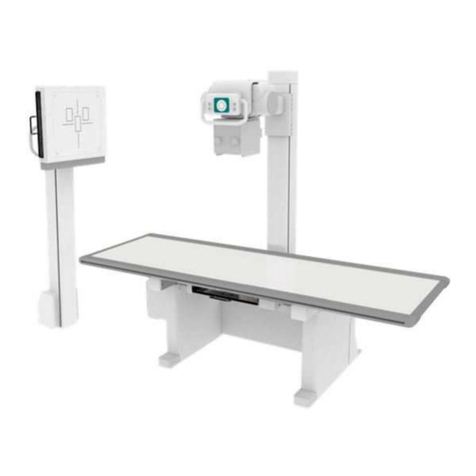
Pro-tec
Pro-tec PRS 500 C User manual
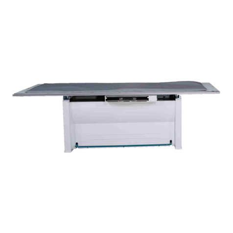
Pro-tec
Pro-tec PROGNOST F 7041-5-8701L User manual

Pro-tec
Pro-tec ECOMAX User manual
Pro-tec
Pro-tec UCARE User manual
Pro-tec
Pro-tec PROGNOST B User manual
Pro-tec
Pro-tec optimax 2010 User manual
Pro-tec
Pro-tec COMPACT 2 User manual

Pro-tec
Pro-tec optimax 2010 User manual
Pro-tec
Pro-tec ECOMAX User manual
Pro-tec
Pro-tec COMPACT 2 NDT User manual

