sidhil SOLITE-PRO User manual
Instructions for use
Community Care Bed Range
www.sidhil.com

2
Still making it better...
Excellence in customer
service is our key
objective. Alongside our
focus on innovation,
research and product
development, we use
our UK manufacturing
facility to ensure optimum
levels of product and
spares availability,
with unparalleled
levels of reliability and
performance.
Corporate social responsibility
is also an issue for Sidhil. We
have now received accreditation
to ISO 14001, underlining our
commitment to maintaining the
highest levels of environmental
awareness and sustainability
across our manufacturing
operation.
At Sidhil, everything we do
is designed around quality.
From our modern and efcient
manufacturing plant in Halifax,
West Yorkshire, we manufacture
a range of products for the
healthcare market using leading
edge production technology and
nishing processes.
We are the only remaining
volume manufacturer of
hospital beds in the UK,
bringing together innovation
in product development,
sales, customer service and
logistics to provide clear
benefits for our customers
in terms of flexibility, short
production timescales and
support from our nationwide
network of service and
maintenance centres.
Welcome to Sidhil

3
1. INTRODUCTION ..............................................................................
2. CONTACT INFORMATION ..............................................................
3. PRODUCT DESCRIPTION ...............................................................
3.1 Environment .......................................................................................
3.2 Intended Patient Group........................................................................
3.3 Intended Use.......................................................................................
3.4 Product Overview ...............................................................................
3.5 Features ..............................................................................................
4. SAFETY ..............................................................................................
4.1 Warnings and Cautions ........................................................................
4.2 Risk Assessment ..................................................................................
4.3 Contraindications ................................................................................
4.4 Bed Load .............................................................................................
4.5 Training ...............................................................................................
4.6 General Warnings ................................................................................
5. TRANSPORT AND STORAGE ..........................................................
6. SYMBOL DEFINITION ......................................................................
7. PARTS IDENTIFICATION ..................................................................
8. BED ASSEMBLY AND PREPARING FOR USE ...................................
8.1 Removal from the Transport Stand .......................................................
8.2 Assembling the Bed .............................................................................
8.3 Fitting the Electrical System .................................................................
8.4 Cable Routing ......................................................................................
8.5 Ancillary Product Cable Routing ...........................................................
8.6 Fitting the Side Rails .............................................................................
8.7 Storing the Transport Stands ................................................................
8.8 Extending the Bed ................................................................................
8.9 Side Rails and Mattresses ......................................................................
8.10 Side Rail Safety ...................................................................................
8.11 Checking the Bed ...............................................................................
8.12 Knee Break / Leg Section ...................................................................
8.13 Lockout function ................................................................................
8.14 Installation / Preparing for Use............................................................
9. OPERATION OF THE BED .................................................................
9.1 Operational Limits ...............................................................................
9.2 Brake System .......................................................................................
9.3 Operating the Side Rails (when fitted) ...................................................
9.4 Electrical Operation .............................................................................
10. ASSEMBLY ONTO THE TRANSPORT STANDS .............................
11. POWER FAILURES ...........................................................................
12. BATTERY CHARACTERISTICS (BATTERY BACKUP VERSIONS ONLY).......
13. DECONTAMINATION .....................................................................
13.1 Cleaning and Disinfection Guidelines ..................................................
13.2 Steam Cleaning ..................................................................................
14. MAINTENANCE ..............................................................................
14.1 General Inspection ............................................................................
14.2 Fault Finding ......................................................................................
14.3 Servicing ............................................................................................
15. DISPOSAL OF PARTS ......................................................................
16. SPECIFICATION ..............................................................................
16.1 Bed Data ............................................................................................
16.2 Electrical Data ....................................................................................
17. ELECTROMAGNETIC COMPATIBILITY (EMC)...............................
18. ACCESSORIES .................................................................................
18.1 Mattress / Side Rail Compatibility Chart .............................................
19. WARRANTY ....................................................................................
CONTENTS
4
4
5
5
5
5
6
6
7
7
7
7
8
8
9
10*
11
13
14*
14*
15*
16*
17*
17*
18*
20*
20*
21*
21*
22*
23*
24*
24*
27
27
27
28
28
30*
32
32
33*
33*
34*
35*
35*
35*
36*
37
38
38
39
40
41
43
44
* Highlighted pages are for authorised personnel reference only, if in
doubt contact Sidhil Ltd. or your local distributor.
Warning

4
Thank you for purchasing this product. These instructions for use should be read
carefully before operating the bed. Please ensure that you understand all instructions,
if you have any questions concerning the operation or maintenance of the bed please
contact your provider / supplier who will provide you with expert professional advice.
Sidhil recommend the bed is assembled and maintained by Sidhil service engineers or
qualified personnel.
1. INTRODUCTION
2. CONTACT INFORMATION
For any service, warranty, sales or customer service information regarding this product
please contact your provider or if in doubt contact Sidhil Ltd. at the following address:
Please quote the product serial number on all correspondence. This can be found on
the identification labels, which are located on the inside of the backrest section frame,
on the inside of the leg section frame, and on the lower section of each bed end.
Sidhil Ltd.
Sidhil Business Park
Holmfield
Halifax
West Yorkshire
HX2 9TN
United Kingdom
For Service & Support outside the United Kingdom & Northern Ireland please contact
the local distribution company from where this equipment was purchased. Failure to
do so may result in the manufacturer’s warranty becoming void.
Service & Maintenance
Tel: +44 (0)1422 233136
Fax: +44 (0)1422 233010
Spares
Tel: +44 (0)1422 233138
Fax: +44 (0)1422 233010
Customer Service
Tel: +44 (0)1422 233000
Fax: +44 (0)1422 233010
w: www.sidhil.com

5
3. PRODUCT DESCRIPTION
3.1 Environment
Your bed is intended for use in the following environments:
• A domestic area where the bed is used to alleviate or compensate for an injury,
disability or disease.
• A long term care area where medical supervision is required and monitoring is
provided if necessary (e.g. nursing homes, rehabilitation facilities, geriatric facilities
etc.).
The intended use of the bed is for sleeping / resting and it is intended to assist in
diagnosis, monitoring, prevention, treatment, alleviation of disease or compensation
for an injury or handicap, as determined by the end user and care staff.
The bed frame is intended to support a single adult. A risk assessment must always
be performed on the suitability of the patient to the bed frame and any ancillary
accessories.
The bed is typically transported to the end user environment on a distribution vehicle
and installed by community health care loan store installation staff. The bed sections
can be assembled onto transport stands, intended to maximise the manoeuvrability
of the bed during transportation whilst minimising the footprint of the bed on the
distribution vehicle. Installation staff are responsible for performing the initial set up
of the bed, including side rail assembly, handset setup, and the set up of any other
compatible accessories as specified by the professional user.
The patient is only defined as such when situated in the bed. Both the professional user
and patient are intended to operate the bed. It is the professional user’s responsibility
to determine that the patient is both mentally and physically capable of operating the
bed functions with minimal risk of personal injury.
The bed is intended to provide patients with optimum independence and freedom of
movement and carers with greatly reduced manual handling needs via the electrically
operated movable sections.
For assistance in setting up, using or maintaining your bed or to report unexpected
operation refer to the contact details found in section 2.
The bed frame is intended for an adult who is up to 191kg in weight. A lower (or upper)
age limit is not defined as it depends on the physical size of the patient in relation to
the various proportions and gaps around the bed frame. Patients must be in excess of
146cm in height ranging up to 201cm (bed extended) and have a BMI greater than 17.
3.3 Intended Use
3.2 Intended Patient Group

6
• Electrically operated backrest, height adjustment and leg rest angle.
• Auto regressing backrest.
• Electrically operated foot down tilt*.
• Auto contour – simultaneous adjustment of the backrest and leg rest section.
• Battery backup functionality (SOLITE/PRO/BB and SOLITE/PRO/LOW/BB only).
• Patient handset with individual function lockout.
• Integral mattress platform extension.
• Integral leg section extension.
• Optional integral full length side rails.
• Can be broken down into four separate sections.
• Transport stands to aid storage and bed transportation.
3.5 Features
* As standard, the handset provided omits the head down tilt (Trendelenburg)
function for safety reasons. If a Trendelenburg function is required a
replacement handset can be purchased featuring this function. Please refer
to section 18 for the part code, and refer to the contact information in section
2 to order or to request further information – Sidhil recommend the use of
the standard handset when the bed is being used in a domestic environment.
• The Solite Pro Low does not meet the upper height requirements of IEC
60601-2-52, if patient or carer requirements are such that the height range
is deemed to pose a potential hazard the Solite Pro should be used instead,
please refer to the contact information in section 2 to request further
information.
Warning
The handset operates an electronic linear actuator system, which is controlled via a central
control box. The actuators are attached to the moving parts of the bed frame allowing the bed
to be operated via the use of the handset.
Two powder coated steel bed ends support the mattress platform frame, the electrical system
and a set of side rails (when fitted) to provide patient protection; the bed has a safe working
load of 226kg. The bed is manoeuvrable via the aid of four individually lockable castors which
are attached to the bed ends, however it is not designed for patient transportation. The bed can
be disassembled into four separate sections, which can be assembled onto the transport stands
provided with the bed, aiding transportation and storage.
The Solite Pro range of beds are intended to be plugged into a permanent mains supply. A battery
backup version is available for such times that a mains supply is not available or reliable. A low
height version of the bed is also available, providing a solution where falls management is an
important consideration. The low height bed has a minimum and maximum mattress platform
height 100mm lower than the standard height bed.
The bed has one handset, intended for use by both the patient and carer, which provides the
carer with the ability to lock out the use of bed functions as necessary to reduce the risk of
accidental operation. It is the carer’s responsibility to determine that the patient is both mentally
and physically capable of operating the handset with minimal risk of personal injury.
3.4 Product Overview
7
4. SAFETY
4.1 Warnings and Cautions
4.2 Risk Assessment
Before a patient uses the bed a risk assessment must be performed on a patient by
patient basis. The risk assessment should include, but is not limited to:
• Entrapment.
• Falling out of the bed.
• Small adults (and children).
• Patients with learning difficulties.
• Unauthorised people with access to the bed.
• Use of side rails.
Patient conditions for which the use of the Solite Pro and Solite Pro Low bed is a
contraindication are as follows:
• Cervical or skeletal traction.
• Unstable spinal fractures - If bed functions remain unlocked.
• General skeletal fractures - If relevant bed functions remain unlocked.
• Mental capacity not sufficient to operate handset functions safely - If bed functions
remain unlocked.
• Confused, agitated or restless - If side rails fitted and/or in raised position.
• Exceeds maximum patient weight of bed.
• Less than 146cm in length.
• BMI less than 17.
• Less than 40kg in weight
Other contraindications may be relevant which are specific to the patient or care
environment.
4.3 Contraindications
Cautions in these instructions for use highlight potential hazards that if
disregarded could lead to equipment damage or failure.
Warnings in these instructions for use highlight potential hazards that
if disregarded could lead to injury or death.
Caution
Warning

8
Safe working load: 226kg (35½ stone)
Maximum patient weight: 191kg (30 stone)
Safe working load is the sum of:
• Patient mass.
• Mattress mass.
• Accessories mass.
• Mass supported by the accessories (excluding patient mass).
All professional users are to be suitably familiar with the bed’s functionality and its
limitationspriortouse.Patientsaretobefamiliarisedwithhandsetandbedfunctionality
by the professional user at the earliest opportunity, ideally before using the product.
It is the responsibility of the professional user to ensure they are suitably qualified to
use the bed and any associated accessories safely and correctly. If these instructions
for use are not deemed sufficient and the need for training is required please contact
Sidhil Ltd. or your local provider (see section 2) who will be able to discuss training
options with you.
4.4 Bed Load
4.5 Training
Warning
The maximum loads shown above are for the bed to be occupied
by one person only. The bed is not designed to take the weight of
visitors sitting on the side of the bed. Additional weight could damage
components or cause the bed to become unstable, potentially causing
injury.
9
4.6 General Warnings
Warning
• The bed is to be installed and put in to service in accordance with the
information provided in these instructions for use.
• The bed is typically not suitable for child use, if it is to be used for child
occupancy ensure a risk assessment has been undertaken taking in to
account the proportions of the child and dimensions of the bed frame.
• The bed is not suitable for occupants who are less than 146cm in length
- If in doubt please contact your provider or Sidhil Ltd. for further
advice.
• The bed is not suitable for occupants who weigh less than 40kg - If in
doubt please contact your provider or Sidhil Ltd. for further advice.
• The bed is not suitable for occupants who have a BMI less than 17 - If
in doubt please contact your provider or Sidhil Ltd. for further advice.
• Misused electrical equipment can be hazardous.
• Accessories that have not been approved or designed for use with the
bed are not be used - A hazard could be introduced due to product
combination incompatibility.
• Modification of the bed frame is not allowed without the permission of
Sidhil Ltd. – A hazard could be introduced.
• Electrically operated beds should not be used in the presence of
flammable gasses or used in oxygen rich environments – Risk of
explosion / fire.
• Keep the bed away from sources of heat and naked flames (e.g.
cigarettes, electric fires, fan heaters etc.) - Risk of explosion / fire.
• Bed functions must be locked out if there is any doubt about the ability
of the patient to operate the bed safely.
• If children, adults with learning difficulties or even pets pose a potential
risk of intentional or unintentional tampering with the bed its
suitability for use is to be considered during the initial patient / product
risk assessment.

10
FOR AUTHORISED PERSONNEL REFERENCE ONLY
5. TRANSPORT AND STORAGE
The following conditions should be followed when transporting and storing the bed:
• To save space, the bed should be stored on the transport stand.
• The bed should always be stored on a flat and level floor.
• The bed ends should be set to minimum height.
• The bed extension should be set to its innermost position.
• Side rail components, if applicable, (not including side rails) to be kept in the channels on the bed ends
(or stored safely together).
• The brakes should be applied.
• All profiling sections should be secured with hook and loop tape (or similar).
• All functions on the handset should be locked out.
• The bed should be covered to protect it from fluid ingress, dirt, dust etc.
• Beds should not be stored one on top of another.
• Beds should not be stored on their side.
• Ambient temperature: -10°C to +50°C.
• Humidity: 20% - 90% at 30°C – not condensing.
• Atmosphericpressure: 800hPato1060hPa(altitude≤2000m).
Caution
Warning
• The bed is not to be pushed over thresholds - If done so damage to the frame could occur.
• Hook and loop tape (or similar) used for storage should be removed after assembly and
before operation - damage to the frame could occur due to restriction.
• The bed is not intended for patient transport, it is not to be moved out of the room it
is located in with a patient occupying the bed - Risk of patient / carer injury. If the bed is
to be moved within the room with an occupant in the bed a risk assessment in line with
local health and safety policy is to be undertaken in order to ensure that neither staff or
patients are put at risk when moving the bed; this is dependent on the situation and load
on the bed.
• If transporting the bed whilst on its transport stand ensure a risk assessment in line with
local health and safety policy is undertaken to ensure that the staff are not put at risk when
moving the bed, especially in regards to moving up / down inclines and uneven surfaces.
• The bed must never be moved on the transport stand with the locking collars missing or in
the unlocked position - Risk of bed collapse.
• To prevent the risk of cross infection, when removing a bed from an end user’s residence
ensure that all activities in relation to the bed are carried out using disposable gloves and
that they are then discarded appropriately, unless it can be verified that the bed and any
associated accessories have been suitably cleaned and disinfected prior to collection.
• On the return of a bed from an end users residence, prior to putting the bed into storage
ensure it has been cleaned and disinfected in line with the local infection control policy
and / or as defined in section 13 of these instructions for use.
11
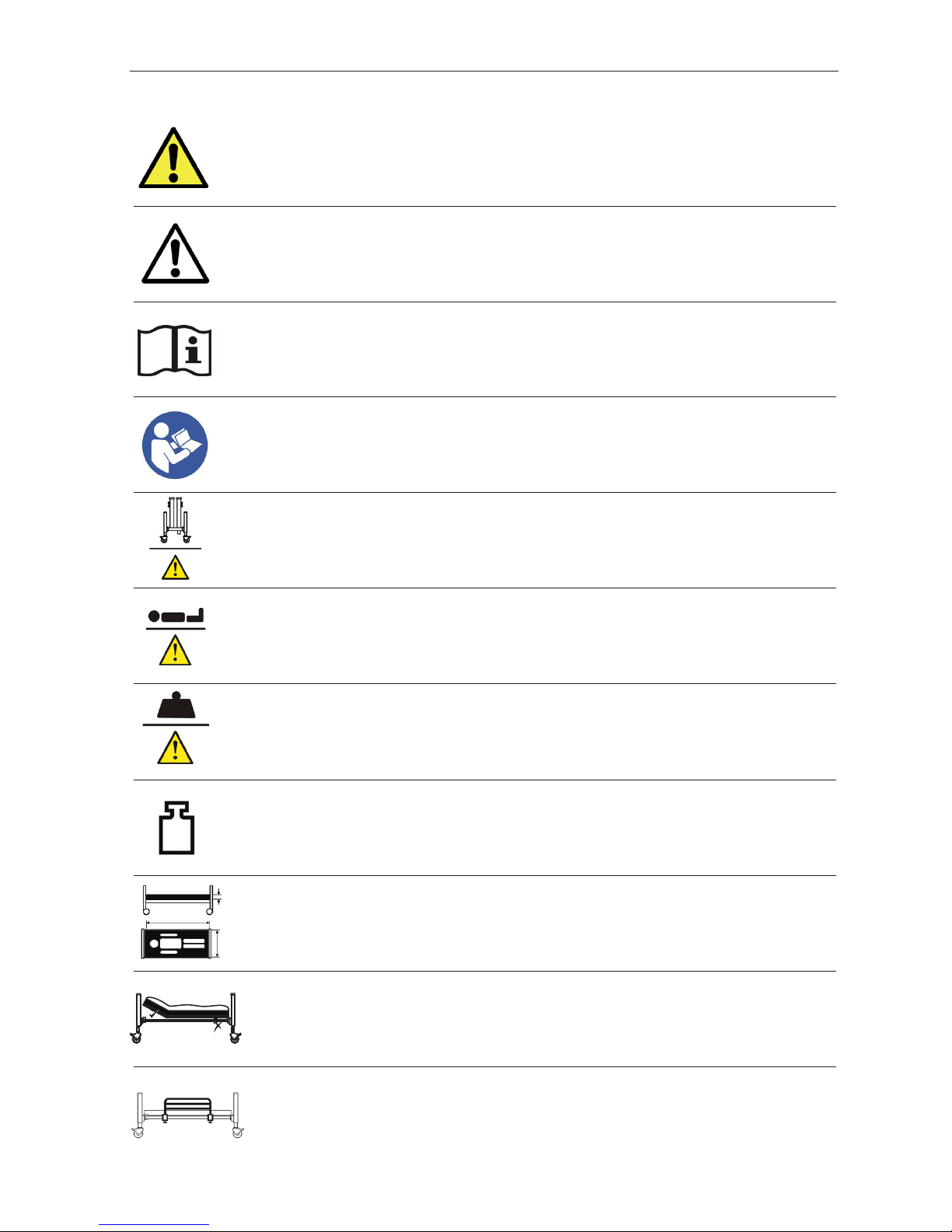
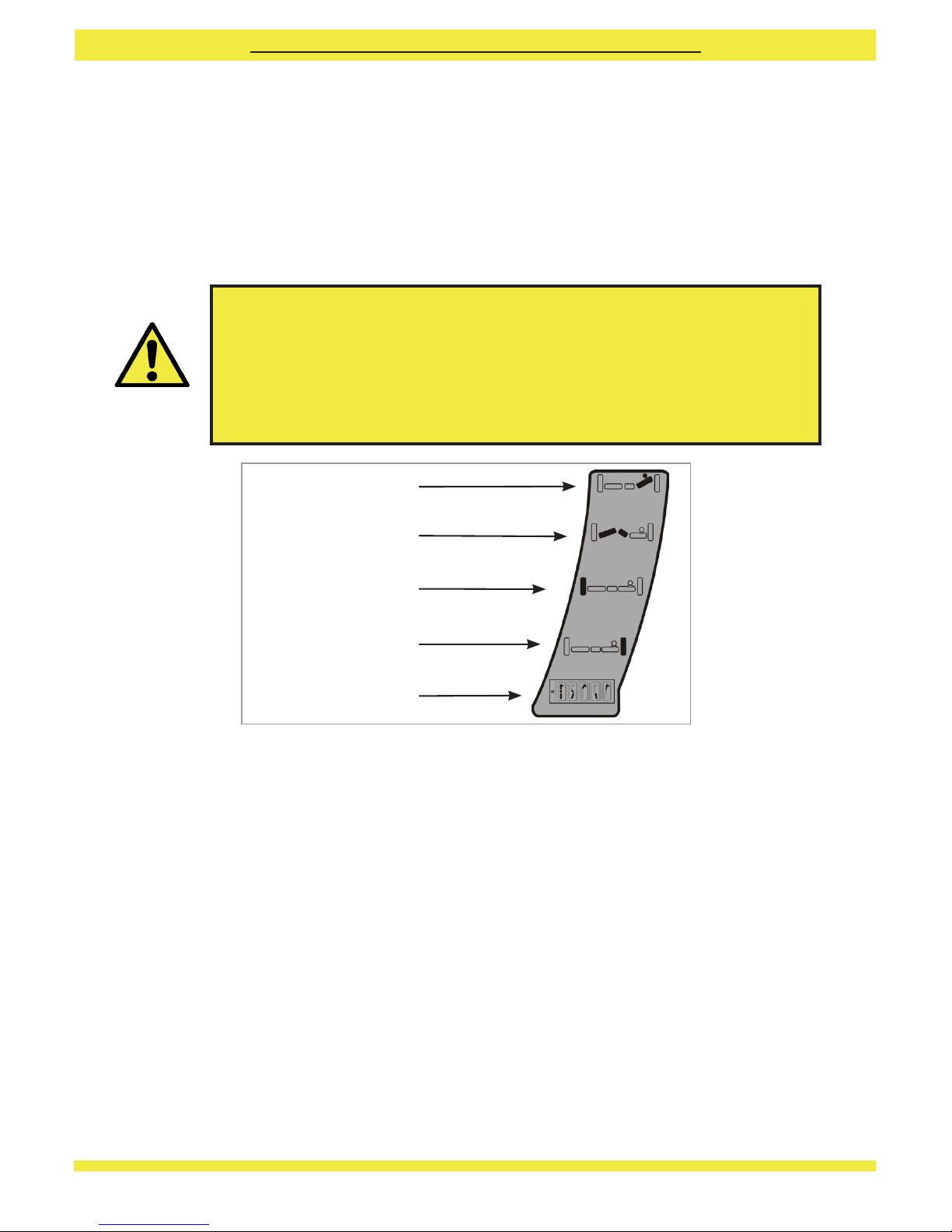
6. SYMBOL DEFINITION
The following symbols are found on this bed:
Refer to instructions for use - Recommended
Failure to read the instructions for use could introduce a hazard
Mass greater than 20kg
Safe working load
Refer to section 4.4
Mattress suitability
Refer to section 18
Detachable side rail suitability
Use of an incorrectly specified or positioned side rail could introduce a hazard.
Total bed weight
On transportation stands
Refer to instructions for use - Mandatory
Failure to read the instructions for use could introduce a hazard
Maximum patient weight
Refer to section 4.4
Mattress strapping suitability
Warning
Beware of potential hazard
Caution
Beware of potential product damage

12
W.E.E.E Label - Found on individual parts of electrical system
(Waste Electrical and Electronic Equipment) Refer to section 15
Minimum patient weight
Temperature limit
Manufacturer
Humidity limit
Date of manufacture
Atmospheric pressure limit
Lot number
Minimum patient height
Minimum patient BMI
Class II electrical device
The user / occupant is protected by at least two layers of insulation between the current carrying parts
(e.g. control box and mains cable) and the metal accessible parts – If damage is noticed to any electrical
component, turn off at the mains and contact your provider or Sidhil Ltd. immediately.
Kneebreak to be used for lifting patient legs only
Type BF applied part
Applied Part: The parts of the bed that come into physical contact with the user / occupant in order for
the bed to carry out its intended function (refer to section 16.2 for a list of applied parts).
Type BF: Applied parts which are electrically isolated from earth and other parts of the medical equipment
- Complying with specific requirements for protection against electric shock to IEC 60601-1.
BMI 17
146 cm
40 kg

13
Bed end x 2
Backrest section x 1
Leg section x 1
Transport stand x 2
Control box clip x 1
Handset lock key x 1
Handset x 1
Side rail channel (if fitted) x 4
1.
2.
3.
4.
5.
6.
7.
8.
9.
10.
11.
12.
13.
14.
15.
16.
Upper side rail (if fitted) x 2
Lower side rail (if fitted) x 2
Accessory socket x 2
Braked castor x 4
Control box / Backrest actuator x 1
Leg rest actuator and battery box (if fitted) x 1
Platform locking collar x 4
Bed end actuator x 2
(Image shown of Solite Pro with integral side rails)
7. PARTS IDENTIFICATION
1
7
11
13
12
3
14
15
2109816
4
5 6

14
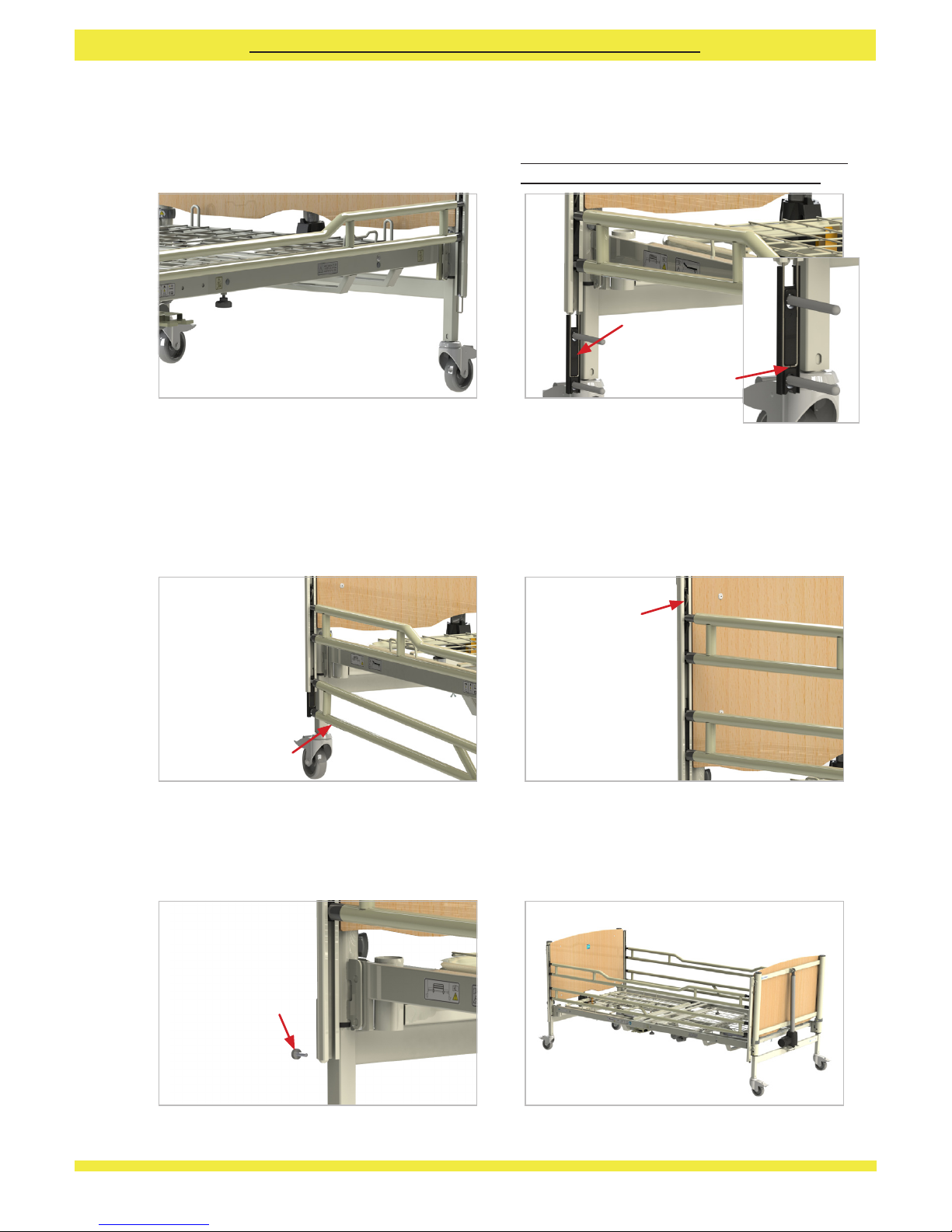
8. BED ASSEMBLY AND PREPARING FOR USE
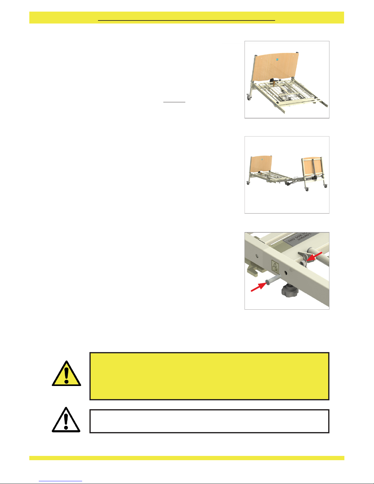
8.1 Removal from the Transport Stand
• Cleartheareaintendedforthebedofanyobstructions
and ensure the surface is level.
• Apply the brakes to the castors.
• Remove the clevis pin, ‘R’ clip and plastic spacer that
secure each transport stand to the backrest section
(8.1.1). These parts will be required when assembling
the bed sections together. Lift the backrest section
off the transport stands and carefully place it flat on
the floor.
• Loosen the hand wheels on the leg section that secure
it to the transport stands (8.1.2). Lift this section off
the transport stands and carefully place it flat on the
floor.
• Lift the locking collars slightly and rotate inwards
on one of the bed ends so that they are both in the
unlocked position (8.1.3). Refer to the warning label
on each collar to identify the unlocked position.
• Carefully lift the end of the transport stands away
from the unlocked bed end and place carefully against
a wall or on the floor. If placing against a wall ensure
the castor brakes are applied.
Note: when the transport stands are lifted
away neither bed end will be supported.
• Rotate the locking collars inwards on the remaining
bed end so that they are in the unlocked position.
• Carefully lift the ends of the transport stand away
from this bed end. The bed has now been separated
into its constituent parts.
No tools are necessary for the assembly of the bed. The assembly procedure is as
follows:
8.1.1 Clevis pin, spacer, and ‘R’ clip
removal
8.1.2 Hand wheel
Warning
8.1.3 Locking collar in unlocked
position
• Before attempting to assemble the bed ensure these instructions have been read and fully
understood.
• Only qualified personnel are to assemble and prepare the bed for use, if in doubt contact
Sidhil Ltd or your local distributor.
• Ensure a risk assessment in line with local health and safety policy is undertaken to ensure
that staff are not put at risk when performing assembly activities.
• Take care when disassembling the bed from the transport stand, the sections are of
considerable weight.
FOR AUTHORISED PERSONNEL REFERENCE ONLY
15
8.2 Assembling the Bed
• Whilst supporting one of the bed ends, lift one
of the mattress platform halves and hook into
the bed end (8.2.1). Adjust the position of the
mattress platform half if necessary to ensure
it is hooked centrally onto the bed end. Turn
the locking collars into their locked position,
indicated by the warning label on the collar.
When turning the collar to the locked position
it will rise and then fall, this is the self locking
mechanism engaging. Note: If this action is
being undertaken by a single person Sidhil
recommend that the castors are braked
before assembly commences.
• Repeat for the remaining bed end and mattress
platform half.
• Release the brakes on the castors on both bed
ends.
• Bring both halves of the bed together (8.2.2)
and align each section so that the spigots in
the backrest section locate into the open tube
ends in the leg section. Pull the two sections
together and tighten the two hand wheels.
• Place the clevis pins through the holes by both
central joints with the head of the pin on the
outside of the bed. Place the plastic spacer
over the end of the pins and insert the ‘R’ clips
from the top of the bed through the hole in the
pin (8.2.3).
8.2.1 Bed end and backrest
assembled
8.2.3 Clevis pin, spacer, and R clip
fitting
8.2.2 Bring assembled bed halves
together
Caution
Warning
• The bed must never be used if the hand wheels and / or clevis pins and associated ‘R’
clips are loose or missing - Risk of bed collapse.
• The bed must never be used with the locking collars in the unlocked position or if
missing - Risk of bed collapse.
Ensure all tie wraps/hook and loop tape (or similar) securing any of the sections in place
are removed prior to operation - Damage to the frame could occur.
FOR AUTHORISED PERSONNEL REFERENCE ONLY
16
8.3 Fitting the Electrical System
• Once all the cables are connected they are to be secured in place by attaching the
supplied retaining clip to the control box.
• Drive the bed to its maximum height then secure the actuator cables in the twist
clips under the mattress platform (refer to section 8.4). Ensure each bed end
actuator cable has enough free cable to allow full movement of the actuator.
Note: The plugs only fit into the ports in one orientation. Ensure the cables
are plugged fully into the control box.
• Plug the actuator and handset cables into the control box. The control box has
a label showing the correct port into which the corresponding cable should be
inserted (8.3.1).
Head end actuator
Foot end actuator
Backrest actuator
Knee break actuator
Handset
Warning
The two bed ends are identical however plugging the actuators into
the correct ports is important to ensure the bed ends operate as
intended - Risk of the bed having the ability to go into head down tilt
accidentally if incorrectly plugged in, creating a potential hazard when
in use.
8.3.1 Control box label
FOR AUTHORISED PERSONNEL REFERENCE ONLY
17
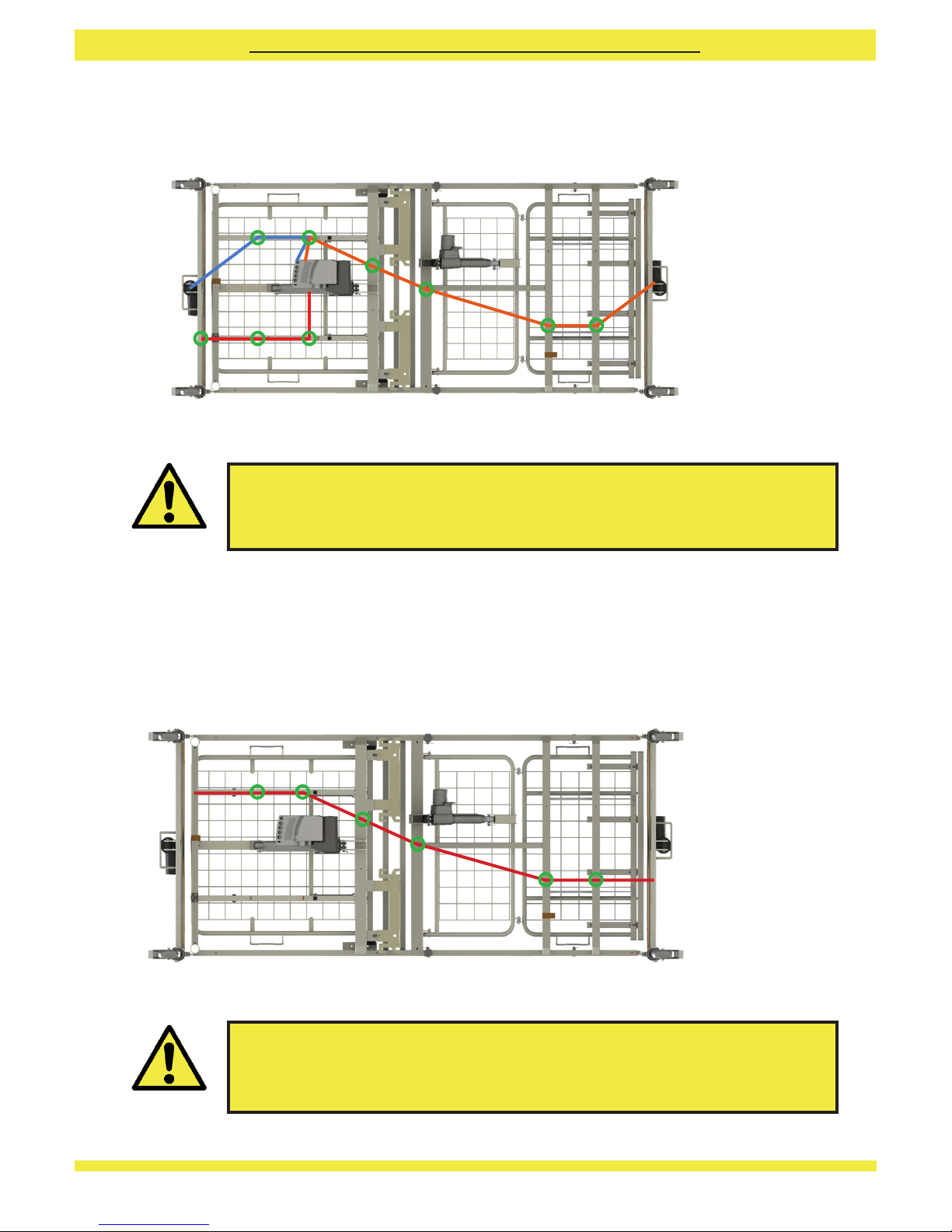
8.4 Cable Routing
The actuator cables are to be routed on the bed frame as shown below:
8.5 Ancillary Product Cable Routing
When fitting ancillary electrical equipment the ancillary mains cable is to be routed
using the twist cable clips located underneath the bed. These clips are shared with the
bed’s actuator cables.
Ensure all ancillary cables are free from moving parts and are not under
excessive tension to avoid cable damage - Damaged cables can create a
risk of electrocution / fire.
Ensure all cables, in particular the mains cable, are free from moving parts
and are not under excessive tension to avoid cable damage - Damaged
cables can create a risk of electrocution / fire.
Cable Clips
Mains cable
Head End Actuator
Cable
Foot End Actuator
Cable
Ancillary product
cable routing
Warning
Warning
8.4.1 Bed cable routing
8.5.1 Ancillary product cable
routing
FOR AUTHORISED PERSONNEL REFERENCE ONLY
18
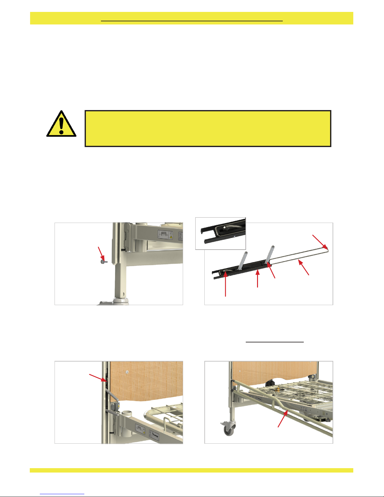
8.6 Fitting the Side Rails
Ensure the bed extension is positioned at the correct length for the side rails that are
being fitted (extended length or standard length side rails). Refer to section 8.8 for
details of how to adjust the bed extension.
Raise the bed to approximately the midpoint of its height range. Refer to section 9.4 for
details of handset operation.
Note: if the side rail finger blocks are already located inside the side rail
channels, remove the finger blocks from just one end of the bed, then proceed
to assembly stage 4 below.
Unscrew the thumb wheels located at the
bottom of each side rail channel.
Insert the top side rail block into one of the
side rail channels until it latches in the lowest
position; note the correct orientation of the
block (release latch to top).
Slide the top side rail, identified by a bent bar, over
the fingers in the top side rail block. This must be
oriented so the bent bar is at the top, otherwise
assembly will not be possible.
Clip the side rail wire over the top side rail block,
identified by the metal release latch at one end.
1.
3.
2.
4.
Latch to top
Bent bar to top
Thumb wheel
If there is any doubt about the assembly of the side rails contact the
provider of the equipment or Sidhil Ltd., incorrectly fitted side rails can
lead to death.
Warning
8.6.1 Thumb wheel removed 8.6.2 Top side rail block and wire assembly
8.6.3 Top side rail block latched 8.6.4 Top side rail inserted
FOR AUTHORISED PERSONNEL REFERENCE ONLY
Top side rail block
Side rail wire
Finger
Gap in side rail wire
Release latch
19
Repeat for the other end of the bottom side rail.
Slide the bottom side rail, identified by two
parallel bars and a diagonal support, over the
fingers in the bottom side rail block. This side
rail must be oriented with the holes facing
downwards. Raise the side rail so it latches in
place at one end.
Reinsert the thumb-wheels into the bottom
of each side rail channel to secure the
channels in place.
Repeat the process for the other side of the bed.
Check the side rails operate correctly to confirm
that they are correctly assembled.
7.
9.
8.
10.
Latched
Holesto underside
Connect another side rail wire and top side rail
block together as described in step 2, and insert
the fingers into the vacant end of the top side rail.
Lift this top side rail block into the channel until
it latches in place.
Release the latch on one of the top side rail blocks
and steadily lower to allow sufficient space for the
bottom side rail block to clip over the lift wire.
It is essential that the lift wire is clipped into the
bottom side rail block in the correct location.
5. 6.
Lift wire location
Bottom side
rail block
8.6.5 Top side rail assembled
8.6.9 Thumb wheel re-inserted
8.6.7 Bottom side rail inserted
8.6.10 Side rails fitted
8.6.8 Side rail raised
8.6.6 Bottom slide block and wire
assembly
Thumb wheel
FOR AUTHORISED PERSONNEL REFERENCE ONLY
20
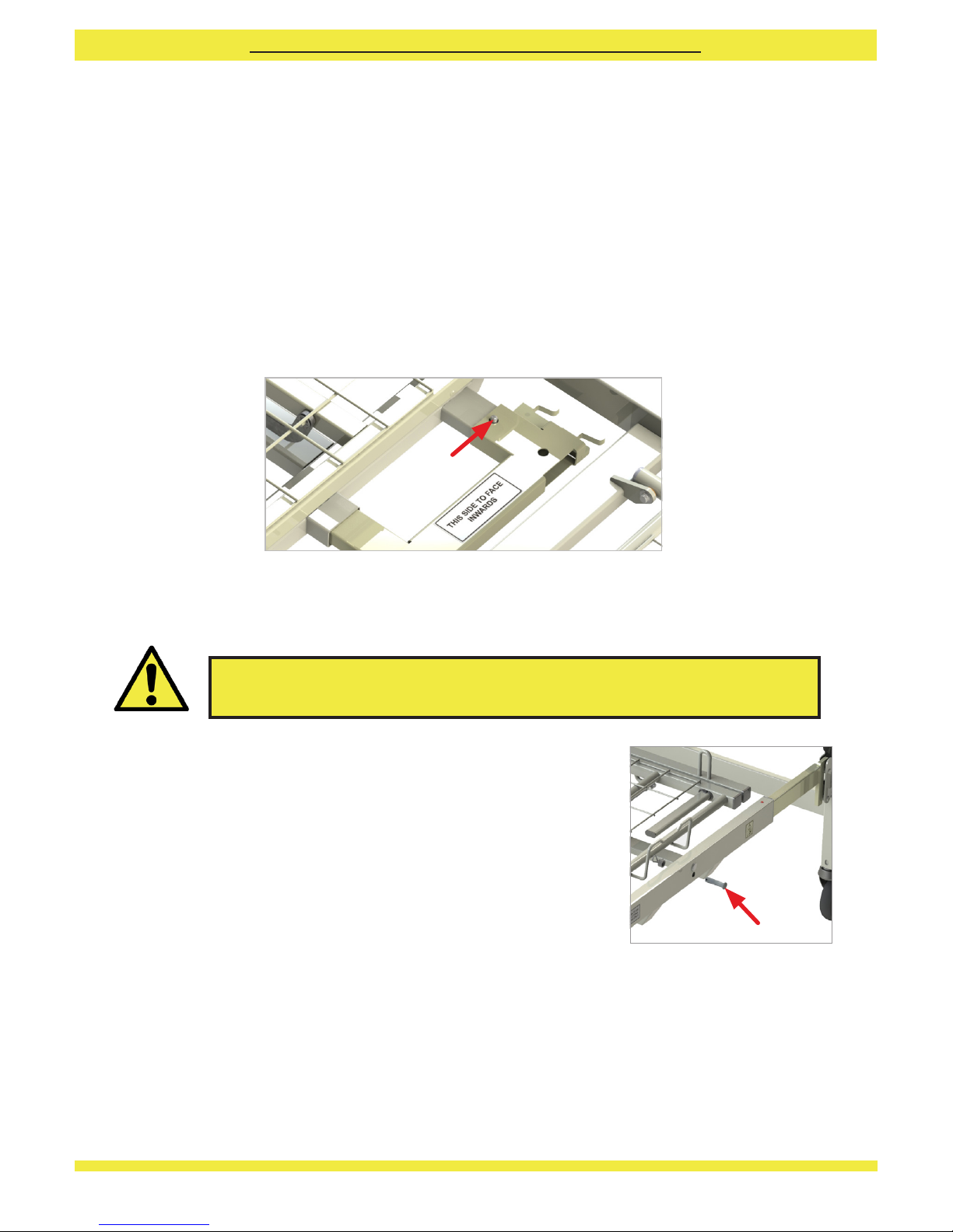
8.7 Storing the Transport Stands
The bed comes complete with integral transport stands and storage brackets. To store
these away once the bed is assembled, follow the procedure below;
• Raise the bed to its full height.
• Holding one transport stand turn it so the words ‘this side to face inwards’ face
upwards.
• Slide the stand into the tubes positioned under the backrest section, push the
spring clip down and push the stand past until the clip springs back locking the
transport stand in position.
• Repeat the procedure for the remaining transport stand.
Spring clip
8.7.1 Transport stand stored
FOR AUTHORISED PERSONNEL REFERENCE ONLY
To extend the bed frame
• Unlock the foot end castors. Whilst holding the foot end near the locking collars,
pull the bed extension out until it reaches its fully extended length (the extension
will stop when it is fully extended).
• Reinsert the ‘R’ clips, spacers, and clevis pins to lock the extension out. If the clevis
pin will not fully insert into the frame, then the extension is not fully extended.
• Reconnect the foot end actuator cable to the bed frame cable clips.
• Flatten all sections and lower the bed to its minimum
height (see section 9.4 for the operation of the handset).
• Ensure the brakes are applied at the head end of the bed.
• Unclip the foot end actuator cable from the bed frame
cable clips (to prevent over extending the cable).
• Remove the ‘R’ clips, spacers, and clevis pins from both
sides of the bed frame, towards the foot end of the bed
(8.8.1).
8.8 Extending the Bed
8.8.1 Removal of extension clevis
pin and extending frame
Warning
Clevis Pin
Never extend the bed when side rails are fitted - risk of side rails falling
and creating a crushing hazard. Remove side rails first.
Table of contents
Other sidhil Medical Equipment manuals

sidhil
sidhil Freedom II User manual

sidhil
sidhil Artemis Instruction manual

sidhil
sidhil E-Med 1200 User manual

sidhil
sidhil Inno V8 Low Installation instructions

sidhil
sidhil 1531 User manual

sidhil
sidhil Artemis User manual

sidhil
sidhil Lullaby User manual

sidhil
sidhil E-Med 1500 User manual

sidhil
sidhil BARIATRIC DYNAMIC User manual

sidhil
sidhil Inspiration Cot User manual

Popular Medical Equipment manuals by other brands


Getinge
Getinge Arjohuntleigh Nimbus 3 Professional Instructions for use

Mettler Electronics
Mettler Electronics Sonicator 730 Maintenance manual

Pressalit Care
Pressalit Care R1100 Mounting instruction

Denas MS
Denas MS DENAS-T operating manual

bort medical
bort medical ActiveColor quick guide

AccuVein
AccuVein AV400 user manual


