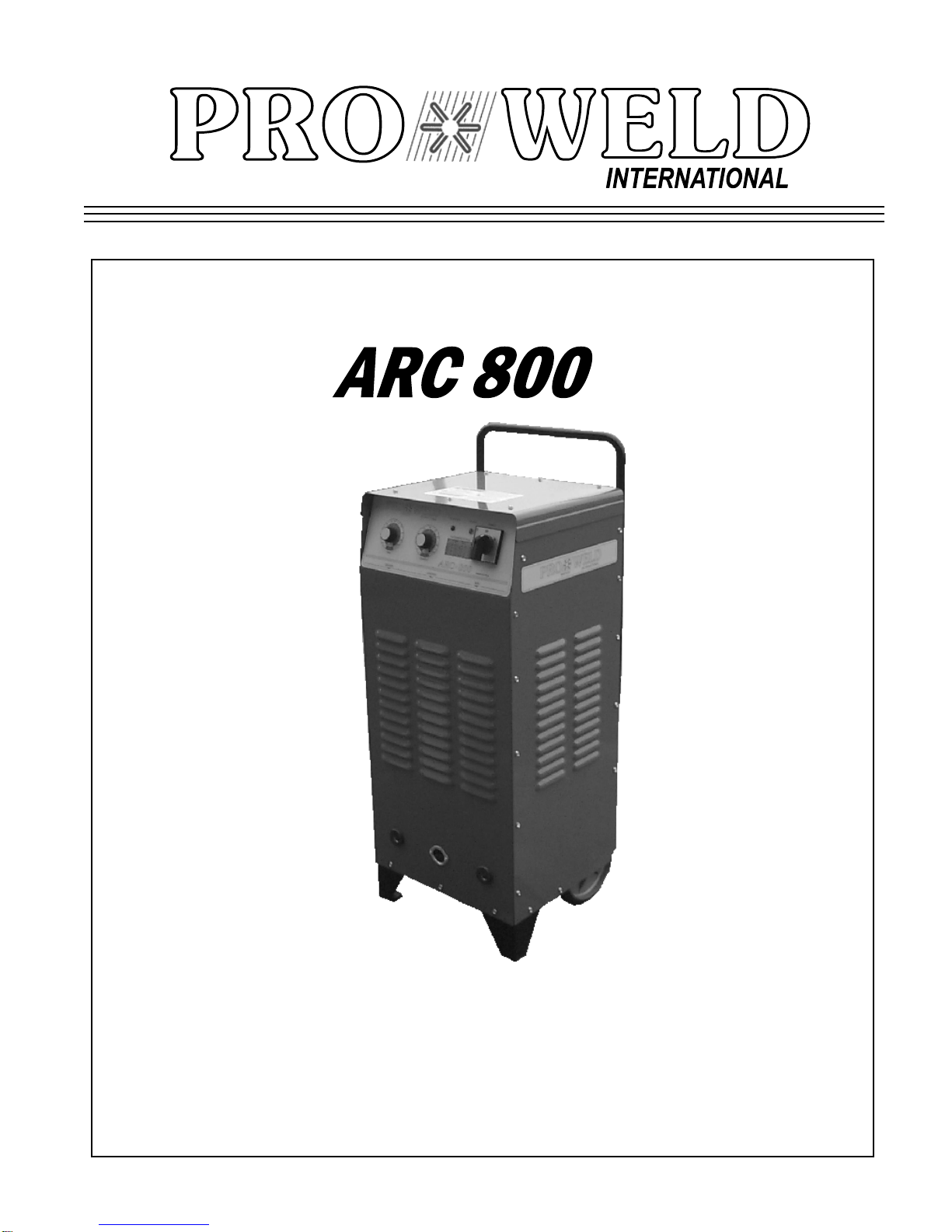
PRO WELD INTERNATIONAL ARC 800 User manual
OPERATION/MAINTENANCE
MANUAL


ARC 800
PRO WELD
TABLE OF CONTENTS
Sec
tion
1
SAFETY PRECAUTIONS
PAGE
1.0 INTRODUCTION....................................................... 1
2.0 WARRANTY............................................................... 1
3.0 UNPACKING YOUR UNIT....................................... 1
4.0
SUGGESTED SAFETY PRECAUTIONS................
1
4.1
PERSONAL SAFETY PRECAUTIONS……………
1
4.2
POWER SU
PPLY PRECAUTIONS…………………
2
5.0
GENERAL DESCRIPTION.......................................
2
6.0
ELECTRICAL INPUT REQUIREMENT.................
2
7.0
CONTROL PANEL DESCRIPTION......................
3
8.0
WELD GUN SETUP...................................................
3
8.1
PLUNGE LENGTH.....................................................
3
8.2
CHECKING GUN LIFT.............................................
4
9.0
SETTING UP POWER SOURCE..............................
5
9.1
CONNECTIONS AND SETTINGS………………….
5
9.2
WELD TEST INSPECTIONS………………………..
5
10.0
MAINTENANCE………............................................
6
10.1
WELD CABLES……………………………………..
6
10.2
INTERNAL CLEANING…………………………….
6
11.0
TROUBLESHOOTING……………………………..
7
12.0
PARTS LIST………………………………….
8,9,10,11
LIS
T OF FIGURES
1
JUMPER LINK ARRANGEMENT...........................
2
2
CONTROL PANEL FRONT.....................................
3
3
STANDARD GUN SET
-
UP........................................
4
4
WELD INSPECTION.................................................
5
5
FUSE BLOCK..............................................................
6
6
FRONT PANEL………………………………............
8
7
CONNEC
TORS……………………………………….
8
8
CONTROL UNIT
-
INTERNAL VIEW.......................
9
9
CONTROL UNIT
-
INTERNAL VIEW.......................
10
10 CURRENT CONTROL PCB....................................... 11

ARC 800
PRO WELD

ARC 800
PRO WELD
ARC 800
PRO WELD

ARC 800
PRO WELD

ARC 800
PRO WELD
1
.0 INTRODUCTION
Your new stud welding equipment has been carefully co
n-
structed using the finest components and material available.
Used properly, this equipment will give you many years of
profitabl
e, efficient service.
The system incorporates the latest in engineering advances for
complete, reliable end welding of mild ste
el, stainless steel
and aluminum fasteners.
A careful study of this manual will enable you to understand
how the welder operate
s to insure proper performance under
all conditions.
2.0 WARRANTY
The electrical and mechanical components of the stud
welder are thoroughly performance inspected prior to asse
m-
bly in the welder. The assembled welder is completely pe
r-
formance checked. The welder is delivered to you in fun
c-
tional electro
-mechanical condition.
All parts used in the assembly of the welder and its a
c-
cessories are fully warranted for a period of 1 YEAR from the
date of delivery. In addition, the welding capacitors are wa
r-
ranted for a period of 1 YEAR from the date of delivery. The
printed circuit boards used in all proweld equipment are wa
r-
ranted for a period of 3 years.
Under the warranty, the manufacturer reserves the right
to repair or replace, at their option,
defective parts which fail
during the guarantee period. Notice of any claim for warranty
repair or replacement must be furnishe
d to the manufacturer
by the purchaser within ten (10) days after the defect is first
discovered. The manufacturer does not assu
me any liability
for paying shipping cost or any labor or materials furnished
where such cost are not expressly authorized in wr
iting.
The manufacturer does not warrant any parts or acce
s-
so
ries against failures resulting from misuse, abuse, improper
installation, maladjustment, or use not in accordance with the
oper
ating instructions furnished by the manufacturer. The
wa
r
ranty is valid only when studs are purchased from sources
approved by the manufacturer or are of identical specific
a-
tions to the manufacturer’s
3.0 UNPACKING YOUR UNIT
Upon receipt of your unit, place it as close as possible to the
point of installation before unpacking it. Once the unit is u
n-
packed, it is recommended that you inspect it for any physical
damage that may have occurred in shipping.
Your unit has been completely assembled and inspected at
the factory. Upon receipt, the unit must be hooked up to the
recommende
d incoming power before welding.
Place the unit in a large enough area to provide adequate ve
n-
tilation. Do not restrict the air flow around the front louvers
or from the fan at the rear of the unit. Do not allow water to
enter the unit in any way.
4.0 SUGGESTED SAFETY PRECAUTIONS
In any welding operation, it is the responsibility of the welder
to observe all safety rules to insure his or her personal safety
and to protect those working in the area.
Reference is directed without endorsement or recommend
a-
tion to ANSI Z49.1, Safety in Welding and Cutting, and to
AWG Publication A6,1
-
66, Recommended Safe Practices for
Gas
-
Shielded A
rc Welding.
4.1 PERSONAL SAFETY PRECAUTIONS
1. Always treat electricity with respect. Under open circuit
conditions, the welding machines output voltage may be da
n-
gerous.
2. Don’t work on live circuits or conductors. Disconnect the
main power before checking the machine or performing any
maintenance or repair operations.
3. Be sure the welding machine cabinet is properly grounded
to a good electrical ground. Con
sult local electrical codes.
4. Never operate a welder in the rain, or operate a welder
while standing in water. Avoid wearing
wet or sweaty clothes
when welding.
5. Don’t operate with worn or poorly connected cables, and
don’t operate the weld gun with loose cable connections. I
n-
spect all cables frequently for insulation failures, exposed
wires, loose connections and repair as needed.
6. Don’t overload w
elding cables or continue to operate with
over heated cables.
7. Don’t weld near flammable materials or liquids in or near
the
area, or on ducts or pipes carrying explosive gases.
8. Don’t weld on containers which have held combustible or
flammable materials, or on materials which give off flamm
a-
ble or toxic vapors when heated.
9. Be sure to provide proper ventilation when welding in a
PAGE 1

ARC 800
PRO WELD
confined area.
10. Never look at the electric arc without wearing protective
eye shields.
11. Always use the proper protecti
ve clothing, gloves, etc.
12. Never strike an arc when near a bystander who is u
n-
aware of the dangers of ultraviolet light to their eyes.
4.2 POWER SUPPLY SAFETY PRECAUTIONS
1.
Always connect the frame to th
e power supply to ground
in accordance with the National Electrical Code and the
manufacturer’s recommendations.
2.
Installatio
n, servicing, or trouble shooting should be done
by qualified personnel trained to work on this type of equi
p-
ment.
3.
Before servicing this piece of equipment, turn off the di
s-
connect switch at the fuse box.
4.
When in operation, all the covers must be on the equi
p-
ment.
5.0 GENERAL DESCRIPTION
THE PROCESS
Stud welding is a time saving tool which semi
-
automatically
arc welds the FULL
CROSS
-
SECTION of a weld stud to the
base material in a fraction of a second and develops superior
strength over normal arc weldi
ng procedures.
Since the
ARC
-
800
stud welding system provides the proper
arc length and allows you to select the proper arc tim
e and
welding current, the variables that affect weld quality are
minimized.
THE UNIT
The
ARC
-
800
is a compact and portable st
ud welding power
supply capable of welding studs through 1/2” diameter weld
base. The power supply which operates on single phas
e
power has the added feature of weld current regulation that
improves stud welding consistency. Both the weld time and
weld current are infinitely adjustable for preciseness and r
e-
peatability
A specially designed electronic gun control circuit has been
incorporated in this system. If a fault condition occur
s due to
a shorted gun solenoid or a faulty control cable, the circuit
Figure 1
Jumper Link Arrangement
PRIMARY WIRE
DELAY TYPE FUSE
SIZE
-
AWG
GND
SIZE IN AMPS
220V
#4
#10
100
380V
#4
#10
75
415V
#10
#10
50
This unit is equip
ped with input voltage jumper links either installed
or in a bag on the jumper link board to allow operation from different
line voltages. If installed, the jumper links are positioned for the hig
h-
est voltage stated on the nameplate or on the input data label. In either
case the jumper links should always be checked to see if they are pro
p-
erly positioned for the voltage being used.
Open the access door located on the lower portion of the rear panel to
expose the j
umper link board. If necessary, reposition the jumper links
to match the line voltage being used. (see Figure 1)
PAGE 2
6
.0 ELECTRICAL INPUT REQUIREMENT
This welding power source is designed to be operated from
single
-
phase, 60 Hertz, AC power supp
ly which has a line
voltage rating that corresponds with one of the electrical i
n-
put voltage shown on the nameplate or input data label. Ad
e-
quate incoming power must be available to obtain maximum
performance.
The
ARC
-
800
should be operated from a separate fused or
circuit breaker protected circuit. Install two primary leads
plus one ground wire (see table for proper wire and fuse
sizes) th
rough the inlet hole in the rear of the unit, using
proper strain relief. The primary cables connect to terminals
L or line. A third lead (ground connection) should be fa
s-
tened to the terminal labeled “GND”. The other end the
ground lead or cable should be attached to a suitable ground
such as a wa
ter pipe, ground rod, ect.
Use whatever grounding means is acceptable to the local
ele
c
trical inspection authorities. Consult the local electric
utility if there is any question about the type of electrical sy
s-
tem available at the installation site or how proper conne
c-
tions to the welding power source are to be made.
L1
L2
GND
1
2
34
5
6
7
L1
L2
GND
1
2
3
4
5
6
7
PLACE JUMPERS AS SHOWN FOR THE
VOLTAGE BEING USED
INPUT
VOLTS 220/380/415
AMPS 100/ 75/ 50
SINGLE PHASE 50/60 HZ
OUTPUT
VOLTS 42
AMPS 1000
MAX O.C.V. 75
L1
L2
7
GND
52
3
61
4
PRO WELD INTERNATIONAL
ARC-800
415 V
380 V
220 V

ARC 800
PRO WELD
1. A different and correctly sized chuck and ferrule grip are
needed for each different stud diameter and style that will be
wel
ded (see PRO WELD Accessories catalog for help in this
area). The appropriate chuck, or stud holder, is inserted into
the tapere
d chuck adapter and tapped lightly to insure a tight
fit. The ferrule grip is inserted in the hole in the foot and s
e-
cured with the locking screws to hold it in place.
2. Studs must NOT bind or hang up on the foot, ferrule grip,
or ferrule duri
ng the entire stud welding process. To assure
this, the foot/ferrule arrangement must be centered in relation
to the stud to be
welded. To assure centering, loosen the leg
screws that hold the foot to the legs. Place a stud in the
chuck and a ferrule in th
e ferrule grip. With the leg screws
loosened, the foot will move freely in all directions. Adjust
the foot so that the stud is centered in the ferrule and no co
n-
tact occurs between the stud and the ferrule during retraction
or forward plunge of the stud.
3. The “plunge length” is the amount of the stud exposed b
e-
yond the ferrule during initial set
-
up. Set the plunge by loo
s-
ening the leg adjusting screws and moving the foot until the
stud extends 1/8” to 3/16” past the end of the ferrule. Tighten
the
leg adjusting screws after setting the plunge and recheck
centering to be sure the stud is aligned properly in the fe
r-
rule.
4. The lift height, which determines the arc length, has been
preset at the factory and will automatically lift and plung
e the
stud during the welding process. “Lift”, is the distance the
gun will raise the stud above the welding surface during the
weld. This distance governs the voltage and the arc. I
m-
proper lift will cause unsatisfactory welds. Refer to par
a-
graph 8
-
1 if it becomes necessary to adjust the lift height.
5. Make sure that the cables are connected to the power
will prevent gun triggering and eliminate damage to printed
circuit boards.
7.0 CONTROL PANEL DESCRIPTION
ON/OFF SWITCH
The
ARC
-
800 is turned “ON” by turning the knob on the
switch to the “ON” position.
WELD TIME ADJUSTMENT
The weld timer regulates d
uration of the weld current. The
timer is calibrated in seconds from .05 to .6 seconds.
WELD CURRENT ADJUSTMENT
The weld curre
nt is adjustable 100
-900 Amperes.
GUN FAULT LED INDICATOR
The gun fault LED “on” indicates a shorted gun solenoid or a
shorted
control cable. The LED will stay “on” and lock out
the gun from triggering.
TRIGGER LED
The trigger LED “on” indicates a com
plete circuit to the unit
through the gun control cables and gun switch. This LED
will turn “on” whenever gun trigger is pressed
.
8.0 WELD GUN SET
-
UP
8.1 Plunge Length
Figure 2
CONTROL PANEL FRONT
PAGE 3

ARC 800
PRO WELD
source (standard set
-
up is straight polarity
-
Negative to co
n-
troller (or gun) and Positive (ground cable) to the work su
r-
face).
6. Turn on the power supply and adjust the current and time
for the weld base diameter of the fastener to be welded.
7.
Place the gun, loaded with the stud and ferrule, squarely
against the grounded work surface. The main spring in the
gun will ta
ke up the “plunge length” and the ferrule will seat
against the base plate.
DO NOT MOVE THE GUN DURING THE WELD C
Y-
CLE
8. Pull the trigger holding the gun completely still as above.
The gun will lift the stud from the base plate and draw an
arc. The end of the stud and the adjacent material of the base
plate, will be melted by the weld arc.
The gun will then plunge the stud into the molten pool, exti
n-
guishing the arc, to end the controlled portion of the weld
cycle.
9. After the controlled weld cycle, allow the molten metal to
solidify briefly with the work surface to assure completion
of the cycle (about an extra second holding "still" after the
weld
is usually sufficient).
10. Remove the gun from the work by lifting straight away
from the welded stud (this will assure bette
r life to the gun's
expendable accessories). The ferrule may now be removed
by breaking it away from the welded stud to allow in
spect
-
tion of the weld results. After inspection of sample welds the
gun can be adjusted, as per the step in this procedure,
for optim
um results.
8.2 Checking Gun Lift
To measure lift, turn the stud welding unit on and set the
timer to maximum time. (On certai
n units there may be a Lift
Check switch available, and in these cases this switch can be
used to check lift.) Trigger the gun i
n the air, or on a
non
-
grounded or insulated surface, to observe the lift cycle.
Measuring the distance the stud or gun mechanis
m
moves equals lift
-
usually this can be easily done by visual
observation or simple measurement against a static ref
-
erence p
oint (i.e. the ferrule properly seated in the ferrule
grip).
Recommended Lift Settings.
Stud Base Dia.
Lift Setting
Less
than 1/2”
1/16”
1/2” through 3/4”
3/32”
Greater than 3/4”
7/64”
When it does become necessary to adjust lift, you
do so by
removing the rear cap from the gun. This will expose the
rear coil yoke assembly, the set screw and the lift adjusting
screw (Loosen the set screw to avoid damaging the threads
of the lift adjusting screw).
To increase lift: turn the lift adjus
ting screw out (counter
clockwise).
PAGE 4
ARC 800
PRO WELD
9.2 Weld Test and Inspection
Testing of weld quality beyond visual inspection varies
with stud characteristics.
Refer to AWS (
American Welding Society) Structure
Wel
d
ing code AWS D.1Rev. 1
-
76.
Welding procedures are covered in Sections 4.28 and 4.29.
Weld test and inspection is covered in Section 4.30, par
a-
graphs 1 through 4. (American Welding Society, inc., 2501
N.W. 7th. Street, Miami, Fla. 33125)
9
.0 SETTING UP THE POWER SOURCE
9.1 Connections and settings.
CAUTION
Turn the power off before making connections
a)
Connect the male end of the GROUND CABLE to the pos
i-
tive GROUND terminal of the power supply, and secure the
“C” clamp to the base plate. Make sure both connections are
tight and t
he base metal is free of heavy paint or rust at the
ground connection points.
b)
Connect the male end of the COMBINATION CABLE SET
to the negative GUN terminal of the power supply.
c)
Plug in the control cable portion of the COMBINATION
CA
BLE SET into the control cable receptacle in the front of
the power supply.
d)
Set the Time adjustment required for the particular
stud size.
(see table 9
-
1)
e)
Set the Current adjustment to the current setting for the pa
r-
ticular stud size. (see table 9
-
1)
f)
Turn on the power supply by depressing the START button.
Table 9
-
1 Approximate Settings
Stud Base
Weld
Weld
Minimum Plate
Inches
mm
Seconds
Amperes
Inches
mm
1/4
6.4
0.20
425
0.048
1.22
5/16
7.9
0.25
500
0.060
1.52
3/8
9.5
0.33
550
0.075
1.91
7/16
11.1
0.40
675
0.089
2.26
1/2
12.7
0.55
800
0.120
3.05
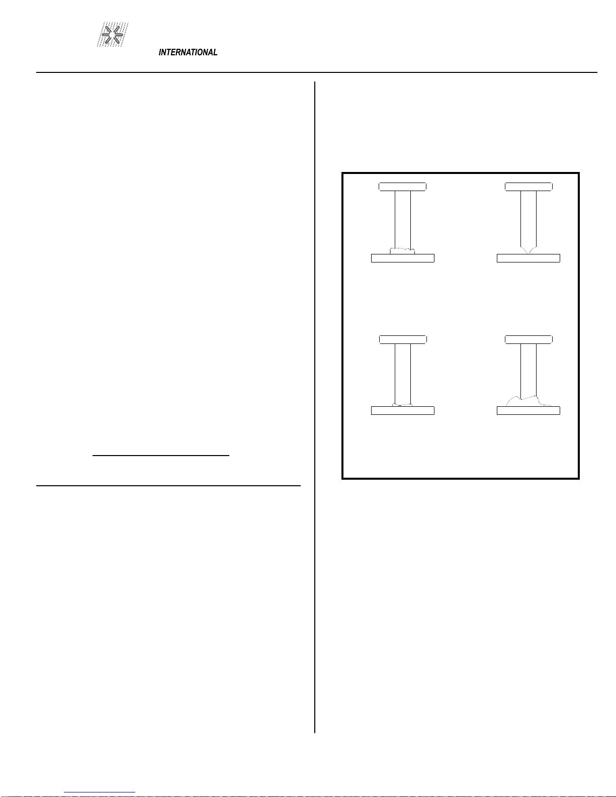
GOOD STUD WELD
A good full fillet
STUD HANG UP
Adjust foot to
insure the stud is
centered in the
ferrule
COLD WELD
Increase weld
current and/or
weld time
HOT WELD
Reduce weld
current and/or
weld time
figure 4
WELD INSPECTION
A. Bend Test
Repeatedly bend the stud away from its axis until failure o
c-
curs.
B. Torque Test
-
Threaded Studs
Twist the stud to point of failure. Apply a twisting tensile load
by using a collar, was
her and nut.
C. Test Results
In an acceptable weld, failure will occur in the stud material
or tear out of a thin base plate. F
ailure in the weld requires
adjustment of procedure, weld time, weld current, or gun
PAGE 5

ARC 800
PRO WELD
setup.
10.0 MAINTENANCE
CAUTION
Electric Shock Can Kill:
•
Do not touch live electrical parts.
•
Shut down welding power source
, and disconnect input
power before inspecting, maintaining, or servicing.
Lockout/tagging procedures consist of padlocking line disco
n-
nect switch in the open position, removing fuses from fuse box,
or shutting off and red
-
tagging circuit breaker or other disco
n-
nec
t
ing device.
MOVING PARTS can cause serious injury.
•
Keep away from moving parts.
HOT SURFACES can cause severe burns.
•
Allow cooli
ng period before servicing.
CAUTION
Read and follow the safety information at the beginning of
this section before proceeding.
1
0.1 Weld Cables
Every three months inspect cables for breaks in insulation. Repair
or replace cables if insulation breaks are pr
esent. Clean and
tighten connections at each inspection.
Figure 5
FUSE BLOCK
10.2 Internal Cleaning
Every six months blow or vacuum dust and dirt from the i
n-
side of the welding power source. Remove the outer encl
o-
sure, and use a clean, dry airstream or vacuum suction for the
cleaning operation. If dusty or dirty conditions are present,
clean the unit monthly.
PAGE 6
F6
F5
F4
F3
F2
F1
1 AMP
15 AMP
SLO BLO
15 AMP
SLO BLO
1 AMP
5 AMP
CERAMIC
4 AMP

ARC 800
PRO WELD
1
1.0 TROUBLE SHOOTING CAUTION
Read and follow the safety information at the beginning of this section before proceeding
Whenever possible, have a qualified electrician do the maintenance and trouble shooting work. Turn the input power off u
s-
ing the disconnect switch at the fuse box before working inside the machine.
Trouble
Possible Cause
What To Do
Unit trips of
f without
1.
Defective main SCR.
1.
Check for defective SCR and
welding.
replace.
2.
Defective sustaining arc SCR.
2.
check a
nd replace.
3.
Unit Overheated.
3.
Allow unit to cool/ then reduce
weld rate to prevent reoccurrence.
4.
Defective the
rmal switch.
4.
Check and replace.
5.
Defective 600
-
0015 P.C. board.
5.
Replace.
6.
Shorted control cables.
6.
Repair.
Low
output.
1.
Low incoming line voltage
1.
Current low line voltage.
2.
Incorrect jumper link connection
2.
Check jumper links on
primary
on primary board.
board for proper voltage.
3.
Defective 600
-
0015 P.C. board.
3.
Replace.
4.
Defective current pot
entiometer.
4.
Replace.
5.
Excessive weld cable length.
5.
Reduce cable length.
Maximum output but
1.
Defective 600
-
0015 P.C.
board.
1.
Replace.
no control.
2.
Open lead going to shunt
2.
Repair broken leads on
(shielded cable).
connection.
3.
Defec
tive current potentiometer.
3.
Replace.
Gun does not lift.
1.
Blown 4 amp fuse.
1.
Check and replace fuse.
2.
Defective 600
-
0015 P.C. board.
2.
Replace.
3.
Defective control cable or
3.
Repair short in cable, replace
gun coil.
gun coil.
4.
Defe
ctive trigger switch on gun.
4.
Replace.
5.
Blown 1 Amp fuse.
5.
Replace.
Gun lifts but does not
1.
Blown 15 amp sustaining
arc fuse.
1.
Check and replace fuse.
weld.
2.
Defective sustaining arc SCR(s).
2.
Replace bad part(s).
3.
Defective 600
-
0015 P
.C. board.
3.
Replace.
4.
Defective choke coil.
4.
Check and Replace.
5.
Open weld cable or bad weld
5.
Check and Repair.
ground connection.
Gun lifts but does not
1.
Defective 600
-
0015 P.C. board.
1.
Replace.
Plunge.
2.
Defective time potentiomete
r.
2.
Replace.
3.
Bind within welding gun.
3.
Perform gun maintenance
PAGE 7

ARC 800
PRO WELD
12.0 PARTS LIST
ITEM
DESCRIPTION
PART NUMBER
1
Front Decal
122
-
0032
2
Knob
102
-
0060
3
LED Red
108
-
0028
4
LED Green
108
-0029
5
Knob
104
-
0043
6
Face Plate
104
-
0042
7
On/Off Switch
104
-
0041
8
Potentiometer
111
-
0001
9
Camlok, Female Panel Mount
10
7-
0002
10
Panel Mount R&S Connector
107
-
0001
PAGE 8
1 2 3 4 5
7 8
9
10
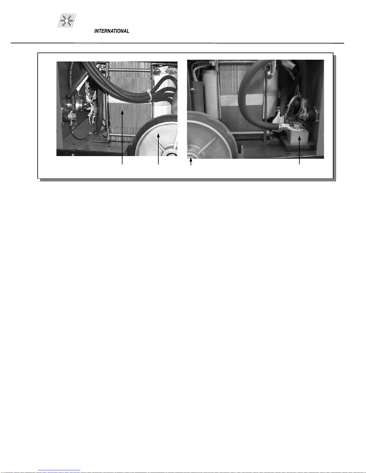
Figure 6
FRONT PANEL
Figure 7
CONNECTORS
6
ARC 800
PRO WELD
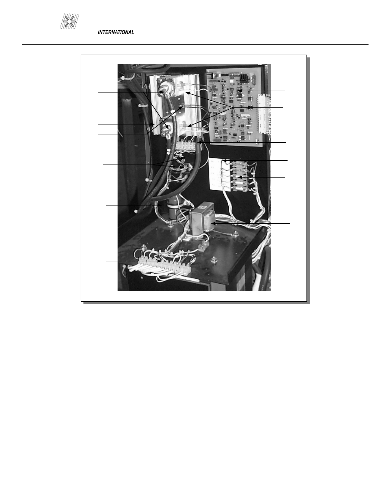
Figure 8
INTERNAL VIEW
PAGE 9
ITEM
DESCRIPTION
PART NUMBER
12
SCR Clamp
102
-
0106
13
Heat Sink
124
-
0050
14
Thermostat
102
-
0032
15
SCR, Isolated 25A 400V
108
-
0042
16
Cap, 1000 MFD 200V
106
-
0024
17
Terminal Strip 12 Pole Euro
102
-
0025
18
Choke Coil
105
-
0004
19
6 Terminal Fuse Bl
ock
104
-
0038
20
Fuse Decal
122
-
0034
21
Terminal Strip 12 Pole Euro
102
-
0025
22
SCR
108
-
0058
23
ARC
-
800 PCB
600
-
0015
12
13
14
15
16
17
18
19
20
21
22
23
ARC 800
PRO WELD
PAGE 10
Figure 9
INTERNAL VIEW
24
25
26
27
ITEM
DESCRIPTION
PART NUMBER
24
M/TRANS/500 220/380/415/50hz
105
-
0012
25
Wheels
102
-
0036
26
Axle Cap
102
-
0027
27
Shunt
102
-
0081
Sheet Metal / Misc. Parts
(NOT PICTURED)
DESCRIPTION
PART NUMBER
Base
101
-
0031
-1
Left Side Panel
101
-
0031
-2
Right Side Pan
el
101
-
0031
-3
Top Cover
101
-
0031
-4
Front Panel
101
-
0031
-5
Back Panel
101
-
0031
-6
MTG Panel
101
-
0031
-7
Compartment
101
-
0031
-8
Rear Door
101
-
0031
-9
Handle
101
-
0031
-
10
Axle
102
-
0046
Handle, Plastic
102
-
0063
Door Latch Knob
102
-
0124
Door Latch Cam
10
2-
0125
ARC 800
PRO WELD
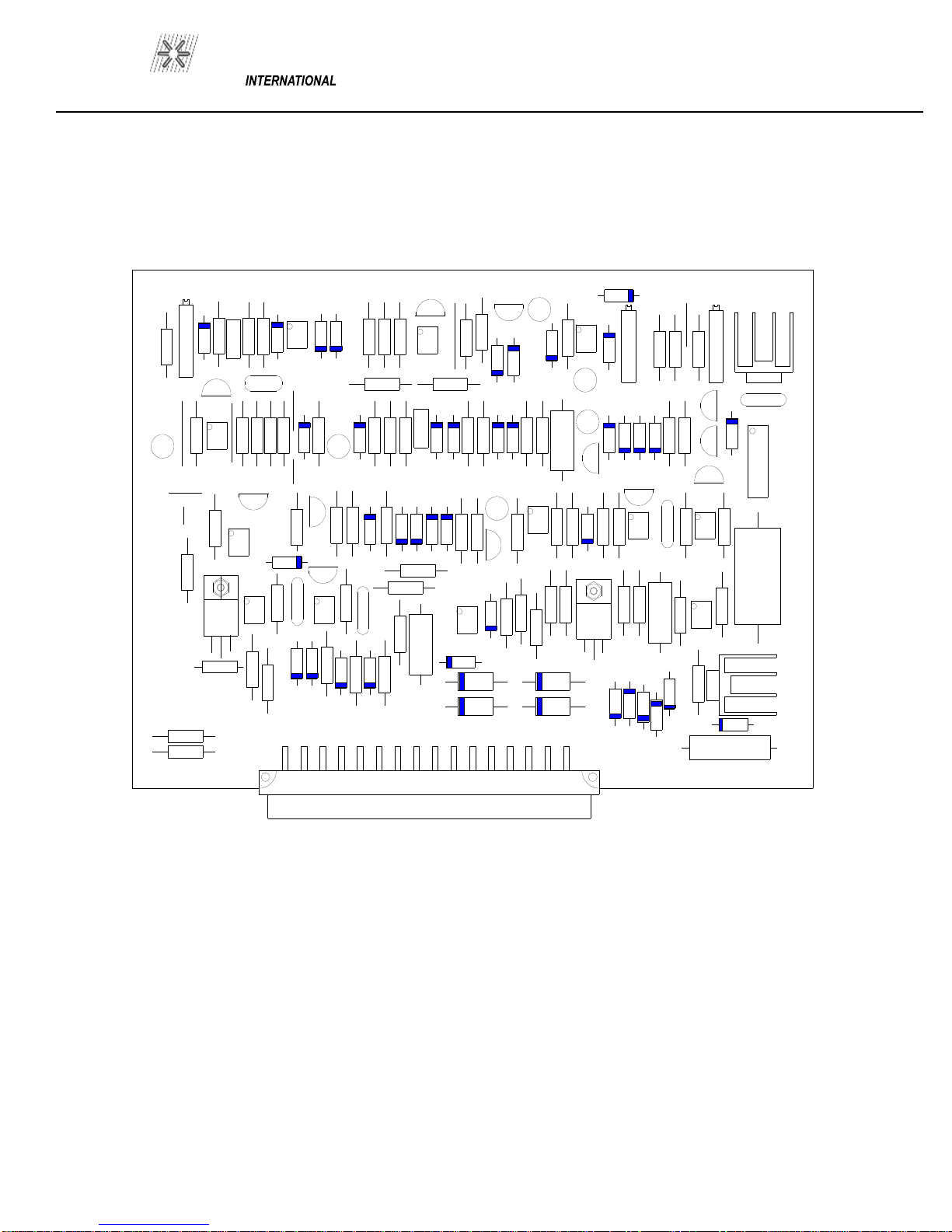
Figure 9
CONTROL P.C. BOARD
P/N 600
-
0015
+
+
+
+
+
+
+
++
+
4004
4004
4004
4004
4004
4004
4004
4004
4004
4004
4004
4004
4004
4004
4004
4004
4004
4004
4004
4004
4004
4004
4004
4004
4004
4004
4004
4004
4004
4004
4004
5404
5404
5404
5404
4746
4746
4728
4734
4744
4734
4734
2.2K 2.2K
2.2K
2.2K
2.2K
2.2K
2.2K
2.2K
2.2K
2.2K
2.2K
2.2K
10K
10K
10K
10K
10K
10K
10K
10K
10K
10K
10K
10K
100
100
100
100
10 10
470
470
470 470
470
470
1K 1K
1K
1K
1K
220 220
220
4.7K
4.7K
4.7K
4.7K
22K
22K
470 22K
22K
22K
10K
3.3K
3.3K
3.3K
47K
1.8K
82K
130K
2.7K
3.9K
3K
390K
47
33K
1M
470M
40V
100M
25V
10M
250V
47M
63V
.47/63
.22/100
4.7
4.7
4.7
10
10
10
.1
.1
.1
.1
.1
A06
A56
A06
A06
A06
A56
A06
A56
A56
TCR22
6027
6027
LM723
LM358
LM358
LM358
LM358
LM358
MOC
3020
H11C6
H11C6
H11G3
MCT6
HP4503
MOC
3020
4004
LM317
24N60
100K
100K
BU806
BTA06
.25
PAGE 11


WELD
PRO
MANUFACTURED BY
MADE IN THE U.S.A.
Table of contents
Other PRO WELD INTERNATIONAL Welding System manuals

Popular Welding System manuals by other brands


Hobart Welding Products
Hobart Welding Products AirForce 375 owner's manual

GF
GF MSA 330 instruction manual

Hakko Electronics
Hakko Electronics FX-888D instruction manual

Abicor Binzel
Abicor Binzel ABIPLAS WELD 100 W operating instructions

EWM
EWM Taurus 355 Basic TDM operating instructions

Thermal Dynamics
Thermal Dynamics PakMaster 100 XL plus operating manual


