ProArc PT-103 User manual

OWNER’S MANUAL
Important
:
Read these instructions before installing, operating or servicing this product.
POSITIONING SYSTEM AND ACCESSORIES
MODEL
:
PT‒103 / PT‒203
WELDING POSITIONERS
(With CB-101/CB-102)
Serial number
:
1808001 ~ and later
Date : Aug. 21, 2018
UNITED PROARC CORPORATION
No. 3 Gungye 10th Road, Pingjen Industrial Park, Tel No:88634696600
Pingjen City, Taoyuan 324, Taiwan Fax No:88634694499
http://www.proarc.com.tw E-Mail:customerservice@proarc.com.tw
RD-8457E


TABLE OF CONTENTS
Introduction
Features
Specification
Operation
Troubleshooting
Part list
Circuit diagram
Introduction...............................................................................................................i
Safety precautions ....................................................................................................ii
Limited warranty.......................................................................................................iii
1.1. General information........................................................................................... 1
1.2. Specification...................................................................................................... 2
2.1 Control panel...................................................................................................... 3
2.2 Operation........................................................................................................... 4
2.3 Installation.......................................................................................................... 5
2.4 Timing diagram .................................................................................................. 6
3.1 Troubleshooting ................................................................................................. 7
4.1 Part List ‒Mechanism (PT-103)......................................................................... 9
4.2 Part List ‒Mechanism (PT-203)........................................................................11
4.3 Part List ‒Control box (CB-101) ......................................................................13
4.4 Part List ‒Control box (CB-102) ......................................................................14
5.1 Circuit Diagram .................................................................................................15

i
INTRODUCTION
A procedure, which if not properly followed, may cause injury to the operator
or others in the operating area.
Read and understand this entire manual regarding the rules for users’ safety
before installing, operating, or servicing the equipment.
Equipment identification
Receipt of equipment
The identification number, model, and serial number of this unit usually appear
on a nameplate attached to the control panel; record these numbers for future
reference.
When you receive the equipment, check it against the shipping documents.
Make sure it is complete and inspect the equipment for possible damage
during shipping. If there is any damage, notify the carrier immediately to file a
claim.
Furnish complete information concerning damage claims or mistake(s) in
shipment to United ProArc Corporation: No. 3 Gungye10th Road, Pingjen
Industrial Park, Pingjen City, Taoyuan 324, Taiwan. Include the equipment
identification number along with a description of the parts in question.
Move the equipment to the installation site before uncrating the unit. Use care
to avoid damaging the equipment when using bars, hammers, etc. to uncrate
the unit.
WARNING
WARNING

ii
SAFETY PRECAUTIONS
Operation and maintenance involves potential hazards. All operators and
personnel should be alerted to possible hazards and precautions should be
taken to prevent possible injury.
Electrical safety
Maintenance
Individual safety
Machine:
﹡The counter, safety device against excess current and electrical installation, are
compatible with its maximum power and its main voltage.
﹡The connection, single-phase or three-phase, is possible on a stand compatible
with the plug of its cable link.
﹡If the cable is connected with the electrical network, the earth must never be cut
by the protection device against electrical shocks.
Work Place:
﹡Be very careful to avoid contact between metal part and phase conductor and the
neutral of electric network.
﹡Electrical messes of different electrical machine and apparatus are connected
between themselves and with the terminal of earth neutral wire.
Interventions:
﹡Before control and repair, see the apparatus is switched off and insulated.
﹡Connection with fixed installation cable is impossible.
﹡It’s on “Stop” and connection is impossible.
﹡Some apparatus are provided with starting circuit HT HF (with a plate). Never
enter into the corresponding switch cupboard.
﹡Only qualified persons are authorized for intervention concerning electrical
installation.
﹡Often check the insulation and connection good state of apparatus and electrical
accessories: taps, appliance cords, coatings, switch, extension cords, etc.
﹡Maintenance and repair of insulating coatings operations are very important.
﹡Do repair with a specialist or better replace defective accessories.
﹡Check regularly the right adjustment and the non-heating of electrical
connections.
﹡The operator must be dressed and protected in relation with his work.
﹡Avoid contacting metal parts connected or accidentally connected.
﹡Wear leather gloves with gauntlet.
﹡Safety clothes:gloves, apron, safety shoes protect the operator and his
assistants against burns of hot parts, projections and slag.
WARNING
ii
SAFETY PRECAUTIONS
Gases and fumes
Fire
Noise
Protection goggle
﹡Gases and fumes produced during the plasma cutting or welding process can
be dangerous and hazardous to your health.
﹡Ventilation must be adequate to remove gases and fumes during operation.
﹡Keep all fumes and gases from the breathing area.
﹡Use an air supplied respirator if ventilation is not adequate to remove all fumes
and gases.
﹡Oil or grease in the presence of oxygen may ignite and burn violently. Keep
cylinders, valves, couplings, regulators, hoses, and other apparatus clean and
free from oil and grease. Oxygen cylinders and apparatus should not be
handled with oily hands or gloves. Do not allow an oxygen stream to contact oily
or greasy surfaces.
﹡Do not use oxygen as a substitute for compressed air.
﹡Fire can be caused by hot slag and sparks.
﹡Remove combustibles from working area or provide a fire watch.
﹡Do not cut containers that have held combustibles. Remove all flammable and
combustible materials in the operating area that may be ignited by sparks.
﹡Noise can cause permanent hearing loss.
﹡Wear proper protective ear muffs or plugs.
﹡Make sure others in the operating are protected from noise.
﹡Welding radiation may cause permanent sight damage
Eyes protection goggle recommended

iii
LIMITED WARRANTY
UNITED PROARC CORPORATION warrants all new equipment to be free from defects in material and
workmanship, provided that the equipment is installed and operated according to instructions stated in this
manual.
UNITED PROARC’s obligation under this warranty policy is expressly limited to the replace or repair, at its
option, of the defected part only. ProArc’s option to repair or replacement of a defected part under this
warranty shall be based on FOB Taiwan basis.
UNITED PROARC CORPORATION shall not be liable for any loss or consequential damage or express
accruing directly or indirectly from the use of equipment covered by this warranty.
This warranty supersedes all previous ProArc warranties and is exclusive with no other guarantees or
warranties expressed or implied.
This warranty excludes the consumable parts that are used in normal operation.

1
1.1 GENERAL INFORMATION
Features - Multiple selection of gear reducer for TIG, MAG/MIG welding application.
- High frequency interference tested.
- Tilting angle ranges from 0o ~120o
-Faceplate through-hole Ø22mm for gas purge application.
-Faceplate with 3 straight slots for 3-jaws fixture (PG-150,450L,500) mounting.
-Control box selection:
CB-101 standard controller:Speed adjuster / Welding timer.
CB-102 advanced controller:Speed adjuster / start delay / overlap timer, and home
sensor.
CB-107 Multi-function controller:PLC with HMI process control to support various E.Z.Arc
system assembly.

2
1.2 SPACIFICATION
Model Unit PT-103 PT-203
Power input ~ 1 Phase 100 ~ 240V 50/60Hz
Capacity(Horizontal/Vertical) kg 100 / 60 200 / 130
Rated eccentricity mm A:180, B:90, C:60, D:45 A:84, B:42, C:28, D:10
Table dimension (E) mm ψ320
Rotation speed rpm A:0.3 ~ 4 B:0.6 ~ 8 C:0.8 ~ 12 D:1 ~ 16
Spindle thru hole mm ψ22
Earthing Amp 200 @ 100% ( 300 @ 40% )
Tilt range deg. 0 ~ 120
Welding timer sec. 0 ~ 60
Overall length (A) mm 460
Overall width (B) mm 315
Overall height (C) mm 340
Center to floor (D) mm 250
Net weight kg 38 42
3
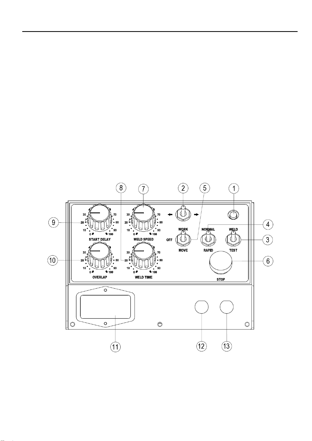
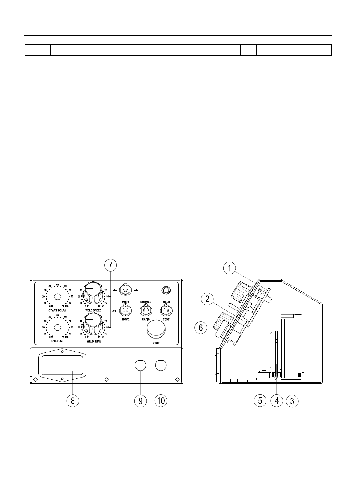
2.1 CONTROL PANEL
1. Power On signal (LED)
2. CW/CCW selection switch. (SW1)
3. Weld / Test mode selection switch. (SW4)
4. Normal / Rapid speed selection switch. (SW3)
5. Work / Move mode selection switch. (SW2)
6. Stop button (STOP)
7. Welding speed adjustment. (VR1)
8. Welding timer adjustment. (VR2)
9. Welding start delay timer adjustmen.t (VR3) (For CB-102)
10. Welding overlap timer adjustment. (VR4) (For CB-102)
11. Power switch. (PSW)
12. Foot switch connector. (P1)
13. Power source connector. (P2)

4
2.2 INSTALLATION
Power cord. Connect the power cord to 1 phase 100V~240VAC
Note:The standard power connector is NEMA-5-15P, different region may select different power
connector.
NEMA-5-15P(Standard) European Adapter(Option) Australian Adapter(Option)
Grounding Stud
To avoid potential electrical damage, please connect the grounding stud to actual ground.
Tilt Lock / Release Handle
Clockwise rotation to lock, counter clockwise rotation to release
Danger! Do not release the tilt handle when part is loaded on the faceplate.
(PSW) Power Switch
I = On,O = Off
LED Indicator Color Identification.
Green:Standby.
Red:Stop button activated.
White:Auto-procedure in progress.
Flashing Green:Homing sequence in progress. (CB-102 only)
Flash Red:Overload.
Forward / Reverse Switch (SW1)
Faceplate rotation direction.
CW ( ) / CCW ( )
Forward
Reverse

5
2.3 OPERATION
WORK / OFF/MOVE Toggle Switch (SW2)
WORK:Enable the system in “WORK procedure” standby. Press/release the footswitch to start “WORK
procedure”. Faceplate rotates according to timer VR1-VR4.
OFF:Reset error and stop work procedure.
MOVE:Enable the system in “MOVE” procedure standby. Press the footswitch to start the rotation, and
release footswitch to stop the rotation. Rotation speed varies according to VR1 or SW3 setting.
NORMAL / RAPID Toggle Switch (SW3)
NORMAL:Faceplate rotation speed varies according to WELD SPEED Knob (VR1).
RAPID:Faceplate rotates with maximum speed.
WELD / TEST Toggle Switch (SW4)
WELD:Welder output(P2) will be enabled when faceplate start rotating in either WORK or MOVE (SW2)
procedure.
TEST:Welder output (P2) is disable in WORK/MOVE procedure.
Note:Welder output (P2) type : Relay dry contact.
Speed Adjustment Knob (VR1)
Adjust rotation speed. CW to increase rotation speed. CCW to decrease rotation speed.
Weld Timer Knob (VR2)
Active in WORK procedure. Weld Timer is the duration of rotation after footswitch is triggered. Adjustable
between 1~60 second.
Start Delay Knob (VR3) (CB-102 only)
Active in WORK procedure. Start delay is the time delay before faceplate rotation. Adjustable between
0-9.9 second.
Overlap Knob (VR4) (CB-102 only)
Active in WORK procedure. Overlap is the time delay after faceplate has hit the home sensor before
faceplate stops rotation. Adjustable between 0-9.9 second
STOP Button
Press to stop the all control. Rotate CW/Pull to reset.
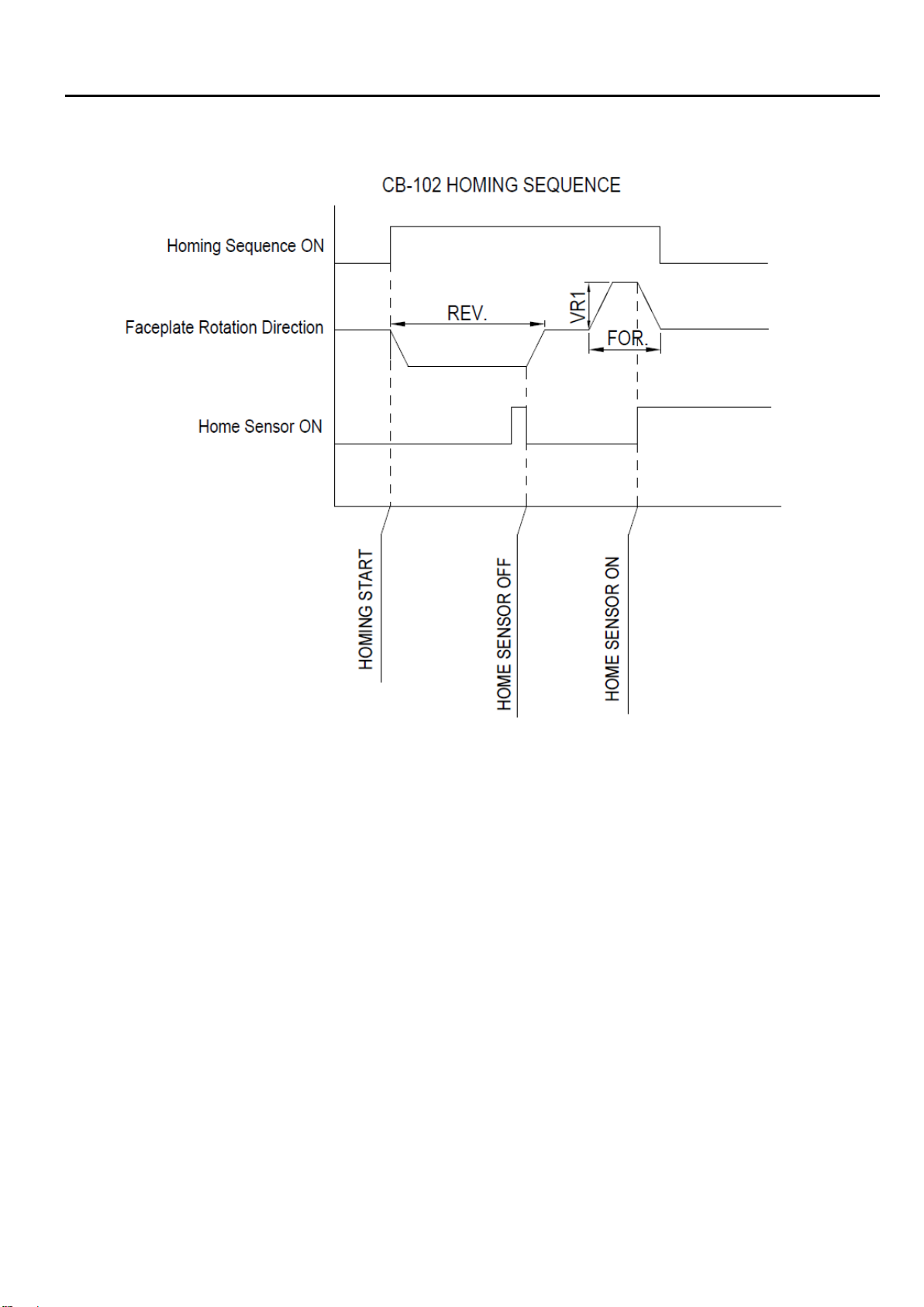
Homing Sequence (CB-102 only)
Homing sequence activates automatically when below condition are met.
A. Right after placing WORK / MOVE toggle switch (SW2) in WORK position.
B. 2 seconds after end of “WORK procedure”.
C. Flipping Forward/Reverse (SW1) switch in “WORK procedure” standby.
D. Reset the STOP button in “WORK procedure” standby.
Note:Homing sequence is divided into 2 stages. Faceplate first rotates in half of maximum speed until
home sensor is triggered and stops. Then faceplate rotates according to VR1 setting to trigger
the home sensor again. Problem may rise in second stage when VR1 is adjusted too small.
Warning:Homing sequence is a semi-automatic process that activates when above conditions
are met. Operator caution is advised.
Variable Speed Foot Switch (Option)
Variable foot switch change welding speed as a percentage of VR1. Example1, Set weld speed
knob 100% and external variable foot switch 50%, the resulting rotation speed is 100% x 50% =
50%. Example2, Set weld speed knob 50% and external variable foot switch 50%, the resulting
rotation speed is 50% x 50% = 25%.
6
2.4 TIMING DIAGRAM (CB-102)

7
3.1 TROUBLESHOOTING GUIDE
SYMPTOMSPOSSIBLE CAUSES / REMEDIES
Power indicator LED does not
illuminate.
A. Blown fuse: Check the fuse, replace fuse when necessary.
B. Input power switch malfunction:Check and replace the power
switch.
C. Check for any loose cable connection between Control Board and
Switch Board.
D. LED malfunction, replace Switch Board.
E. Power supply malfunction, use a voltmeter and check power
supply’s 24VDC output.
Motor has no motion.
A. Damaged motor:
Use ohmmeter to measure CM1 female plug pin
1
& Pin2 and It should read around 2ohm. Replace motor when
reading is either 0 (short circuit between wires) or infinite (broken
wires)
B. Check motor power cable for loose or disconnect cable.
C. Damaged foot switch:
Step on the footswitch and use an ohmmeter
to measure footswitch connector pin4 and pin5
. The reading should
be 0 (short circuit). Replace the footswitch when necessary.
D. Inspect Control Board JP2 for loose connection
E. Inspect Control Board fuse F1
Welder start output no response. A. Damaged Weld / Test toggle switch (SW4), replace Switch Board.
B. Inspect Control Board JP3 for loose connector.
Forward / Reverse rotation
function no response.
A. Switch Board:Step on the footswitch and flip the CW/CCW toggle
switch(SW1). Observe the TR and TL LED on the Control Board
. If
both LEDs have no response, replace the Switch Board.
Speed adjustment no response
A. Take the VR Board JP1 connector off. Rotate the weld speed knob
and measure JP1 Pin1 & Pin2’s resistance. The value should
varies from 0-10kΩ. If there is no variation, check for any
disconnection or replace VR1.
B. Check for any loose cable connection between VR Board and
Switch Board.
C. Normal / Rapid toggle switch (SW3) is set to Rapid position
causing the faceplate to rotate at max speed. Flip to “Normal”
position.

8
3.2 TROUBLESHOOTING GUIDE (CB-102)
SYMPTOMS POSSIBLE CAUSES / REMEDIES
Weld timer function no
response.
A. Take VR Board JP2 connector off. Rotate the Start Delay knob and
measure JP2 Pin 1 & 2’s resistance. The value should vary from
0-10kΩ. If there is no variation, check for any disconnection or
replace VR2.
B. Check for any loose cable connection between VR Board and Switch
Board.
Overload (Blinking Red LED) Inspect the work and make sure it isn’t over-spec (weight /
eccentricity ...etc). Place the Work/Move switch (SW2) in “OFF” position
to reset the system.
Home sequence problem
A. Work / Move switch (SW2) malfunction, replace Switch Board.
B. If the green LED is flashing and there is no rotation, place the
Work/Move switch (SW2) in “Move” position and adjust the welding
speed knob (VR1) to desired speed. Restart the homing sequence.
C. Proximity switch too far:Adjust the proximity switch so it can sense
the homing block correctly.
D. Proximity switch malfunction: use a screwdriver to test trigger the
proximity switch. Replace when necessary.
Overlap delay function
inaccurate or no response
A. Take VR Board JP4 connector off. Rotate the OVERLAP knob and
measure JP4 Pin 1 & 2’s resistance. The value should vary from
0-10kΩ. If there is no variation, check for any disconnection or
replace VR4.
B. Check for any loose cable connection between VR Board and
Switch Board.
Welding start delay function no
response
A. Take VR Board JP3 connector off. Rotate the START DELAY knob
and measure JP3 Pin 1 & 2’s resistance. The value should vary
from 0-10kΩ. If there is no variation, check for any disconnection or
replace VR3.
B. Check for any loose cable connection between VR Board and
Switch Board

9
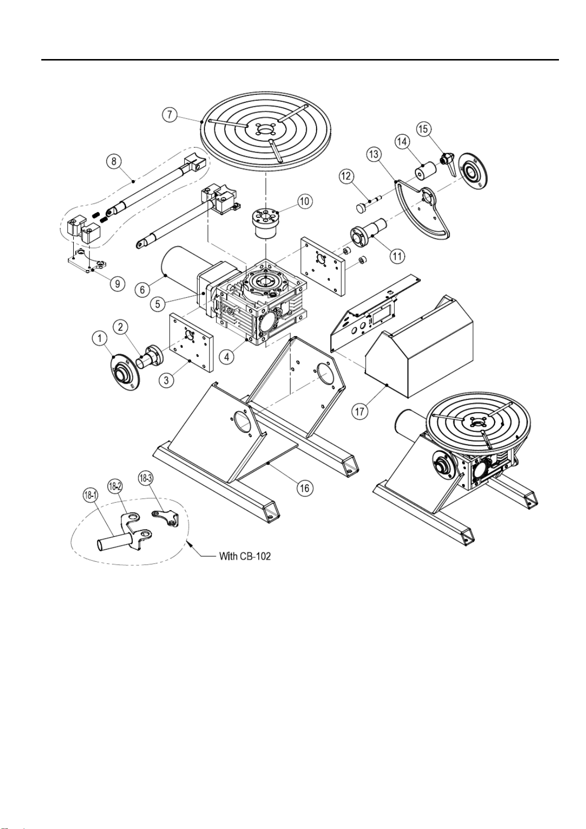
4.1 PART LIST ―MECHANISM (PT-103)
Item.
Part No.
Description
Q’ty
Remark
1 0312-0501 Shaft 2
2
5012-1150200-11
Reducer shaft
1
3 5112-1130000-10 Reducer fixing plate 2
4 0353-0332 Worm reducer 1
5 0351-0109 Gear reducer (15K) 1 A:0.3~4 rpm
0351-0115 Gear reducer (7.5K) 1 B:0.6~8 rpm
0351-0122 Gear reducer (5K) 1 C:0.8~12 rpm
0351-0129 Gear reducer (3.6K) 1 D:1.0~16 rpm
6
*
0361-1002-9
PMDC Motor w/ cable & terminals
1
7 5010-1010100-10 Faceplate 1
8 5010-2040010-20 Grounding brush w/ conducting seat 1
9
5114-12305105000-10
Grounding brush mounting plate
1
10 5114-12305104000-10 Reducer flange 1
11 5012-1150100-20 Reducer Shaft 1
12 5012-2320000-20 Tilt fixing axle 1
13 5012-2300000-20 Tilt angle plate 1
14 5012-2310000-20 Tilt fixing module 1
15 0130-0125 Tilt fixing handle 1
16
5012-1120000-20
Base column plate
1
17 6511-0110 Control box 1 CB-101 (Option)
6511-0120 Control box 1 CB-102 (Option)
18-1
*
3231-2007-9
Proximity sensor w/ connector
1
With CB-102
18-2 5010-4041000-30 Proximity sensor bracket 1 With CB-102
18-3 5010-4040000-30 Fixed sensing plate 1 With CB-102
*Recommended spare parts
10
4.1 PART LIST ―MECHANISM (PT-103)

11
4.2 PART LIST ―MECHANISM (PT-203)
Item.
Part No.
Description
Q’ty
Remark
1
0312-0501
Bearing
2
2 5012-1150200-11 Reducer shaft 1
3 5112-1130000-10 Reducer fixing plate 2
4 0353-0332 Worm reducer 1
5
0351-0109
Gear reducer (15K)
1
A:0.3~4 rpm
0351-0115 Gear reducer (7.5K) 1 B:0.6~8 rpm
0351-0122
Gear reducer (5K)
1
C:0.8~12 rpm
0351-0129
Gear reducer (3.6K)
1
D:1.0~16 rpm
6 *
0361-1002-9 PMDC Motor w/ cable & terminals 1
7 5010-1010100-10 Faceplate 1
8
5010-2040010-20
Grounding brush w/ conducting seat
1
9 5114-12305105000-10 Grounding brush mounting plate 1
10
5114-12305104000-10
Reducer flange
1
11 5012-1150100-20 Shaft 1
12 5012-2360000-22 Tilting worm reducer 1
13
3053-1002
Tilting hand wheel
1
14 5012-2350000-20 Tilting worm shaft 1
15 0331-2003 Self-lubricating bushing 2
16
5012-2340000-20
Mounting bracket
2
17 5012-1120000-20 Base column plate 1
18 6511-0110 Control box 1 CB-101 (Option)
6511-0120
Control box
1
CB-102 (Option)
19-1 *
3231-2007-9 Proximity sensor w/ connector 1 With CB-102
19-2 5010-4041000-30 Proximity sensor bracket 1 With CB-102
19-3
5010-4040000-30
Fixed sensing plate
1
With CB-102
*Recommended spare parts

12
4.2 PART LIST ―MECHANISM (PT-203)
13
4.3 PART LIST ―CONTROL BOX (CB-101)
Item.
Part No.
Description
Qty
Remark
1
*
6622-1010
Printed circuit board
1
Switch board
2
*
3922-1210
Printed circuit board
1
VR Board
3
3326-0008
Power supply
1
4
*
6651-1110
Printed circuit board
1
Motor speed control board
5
3545-5001
Grounding copper bar
1
6
3214-2009
Push button
1
7
3216-0006
Knob
2
VR1~VR2
3747-1001-8
Potentiometer w/Connector
2
8
3331-2001
IEC Inlet filter
1
PSW
9
3242-1116
Foot switch
1
3124-2006
Socket male 5Pin
1
P1
10
3123-2005
Plug female 4Pin
1
3124-2005
Socket male 4Pin
1
P2
*Recommended spare parts.
This manual suits for next models
1
Table of contents
Other ProArc Welding Accessories manuals


Popular Welding Accessories manuals by other brands


AOSafety
AOSafety AOTuffmaster Heat Reflective Aluminum-Infused... brochure

3M
3M Speedglas Utility User instructions

Lincoln Electric
Lincoln Electric W000315558 Safety instruction for use and maintenance

Kemppi
Kemppi SuperSnake GT02SW operating manual

Miller Electric
Miller Electric RGCR-1A owner's manual

GYS
GYS TF 4R manual