ProArc TR-0103 User manual
OWNER’S MANUAL
Important
:
Read these instructions before installing, operating or servicing this product.
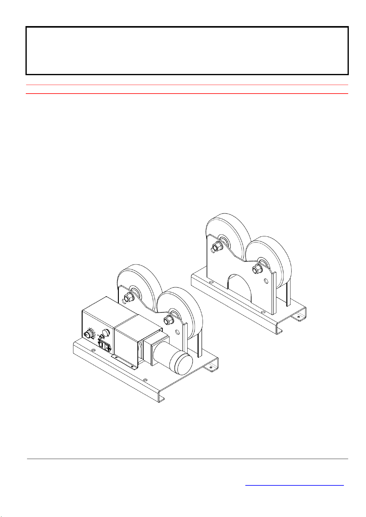
POSITIONING SYSTEM AND ACCESSORIES
MODEL
:
TR ‒0103
TURNING ROLL
Serial number
:
2101001 ~ and later
Date : Jan. 15, 2021
UNITED PROARC CORPORATION
No. 3 Gungye 10th Road, Pingjen Ind. Park, Tel No:88634696600
Pingjen City, Taoyuan 324, Taiwan Fax No:88634694499
http://www.proarc.com.tw E-Mail: customerservice@proarc.com.tw
RD-8468AE


TABLE OF CONTENTS
Introduction
Specification
Operator controls
Part list
Circuit diagram
Introduction....................................................................................................... i
Safety precautions ..........................................................................................ii
Limited warranty...............................................................................................iii
1.1 Specification...............................................................................................1
2.1 Control panel..............................................................................................2
2.2 Installation / Operation................................................................................3
2.3Main wheel adjustment procedure..............................................................4
3.1 Parts list – Main frame (TR-0103P).............................................................5
3.2 Parts list – Main frame (TR-0103I)..............................................................6
3.3 Parts list – Control box................................................................................7
3.4 Parts list – Adapter (Option) ......................................................................8
4. Circuit diagram .............................................................................................9

i
INTRODUCTION
WARNING A procedure, which, if not properly followed, may cause injury to the
operator or others in the operating area.
Equipment Identification
Receipt of equipment
The identification number specification or part number, model, and serial
number of this unit usually appears on a nameplate attached to the control
panel, record these numbers for future reference.
When you receive the equipment, check it against the shipping documents.
Make sure it is complete and inspect the equipment for possible damage
during shipping. If there is any damage, notify the carrier immediately to file a
claim.
Furnish complete information concerning damage claims or mistake(s) in
shipment to United ProArc Corporation:No. 3 Gungye 10th Road, Pingjen Ind.
Park, Pingjen City, Taoyuan 324,Taiwan.Include the equipment identification
number along with a description of the parts in question.
Move the equipment to the installation site before uncrating the unit. Use care
to avoid damaging the equipment when using bars, hammers, etc. to uncrate
the unit.

ii
SAFETY PRECAUTIONS
Electrical safety
Maintenance
Individual safety
Machine:
*The counter, safety device against excess current and electrical installation, are
compatible with its maximum power and its main voltage.
*The connection, single-phase or three-phase, is possible on a stand compatible
with the plug of its cable link.
*If the cable is connected with the electrical network, the earth must never be cut
by the protection device against electrical shocks.
Work place:
*Be very careful to avoid contact between metal part and phase conductor and the
neutral of electric network.
*Electrical messes of different electrical machine and apparatus are connected
between themselves and with the terminal of earth neutral wire.
Interventions:
*Before control and repair, see the apparatus is switched off and insulated.
*Connection with fixed installation cable is impossible.
*It’s on “STOP” and connection is impossible.
*Some apparatus are provided with starting circuit HT HF (with a plate). Never
enter into the corresponding switch cupboard.
*Only qualified persons are authorized for intervention concerning electrical
installation.
﹡Often check the insulation and connection good state of apparatus and electrical
accessories: taps, appliance cords, coatings, switch, extension cords, etc.
*Maintenance and repair of insulating coatings operations are very important.
*Do repair with a specialist or better replace defective accessories.
*Check regularly the right adjustment and the non-heating of electrical connections.
*The operator must be dressed and protected in relation with his work.
*Avoid contacting metal parts connected or accidentally connected.
*Wear leather gloves with gauntlet.
*Safety clothes: gloves, apron, safety shoes protect the operator and his assistants
against burns of hot parts, projections and slag.
Operation and maintenance involves potential hazards. All operators and
personnel should be alerted to possible hazards and precautions should be
taken to prevent possible injury.
WARNING

ii
SAFETY PRECAUTIONS
Gases and fumes
Fire
Noise
Protection goggle
* Gases and fumes produced during the plasma cutting or welding process
can be dangerous and hazardous to your health.
*Ventilation must be adequate to remove gases and fumes during operation.
*Keep all fumes and gases from the breathing area.
*Use an air supplied respirator if ventilation is not adequate to remove all fumes
and gases.
*Oil or grease in the presence of oxygen may ignite and burn violently. Keep
cylinders, valves, couplings, regulators, hoses, and other apparatus clean and
free from oil and grease. Oxygen cylinders and apparatus should not be
handled with oily hands or gloves. Do not allow an oxygen stream to contact
oily or greasy surfaces.
*Do not use oxygen as a substitute for compressed air.
Fire can be caused by hot slag and sparks.
﹡Remove combustibles from working area or provide a fire watch.
﹡Do not cut containers that have held combustibles. Remove all flammable and
combustible materials in the operating area that may be ignited by sparks.
﹡Noise can cause permanent hearing loss.
﹡Wear proper protective ear muffs or plugs.
﹡Make sure others in the operating are protected from noise.
﹡Welding radiation may cause permanent sight damage
Eyes protection goggle recommended

iii
LIMITED WARRANTY
UNITED PROARC CORPORATION warrants all new equipment to be free from defects in material and
workmanship, provided that the equipment is installed and operated according to instructions stated in this
manual.
UNITED PROARC’s obligation under this warranty policy is expressly limited to the replace or repair, at its
option, of the defected part only. ProArc’s option to repair or replacement of a defected part under this
warranty shall be based on FOB Taiwan basis.
UNITED PROARC CORPORATION shall not be liable for any loss or consequential damage or express
accruing directly or indirectly from the use of equipment covered by this warranty.
This warranty supersedes all previous ProArc warranties and is exclusive with no other guarantees or
warranties expressed or implied.
This warranty excludes the consumable parts that are used in normal operation.
1
1. SPECIFICATION
Model Unit TR-0103
Input power --- 1 Phase, AC 110 ~ 240V, 50 / 60 Hz
Drive motor --- PMDC Motor, 24V 65W
Turning capacity Kg 1,000
Load capacity (Drive + Idler) Kg 1,000
Speed range mm / min 80 ~ 1,600
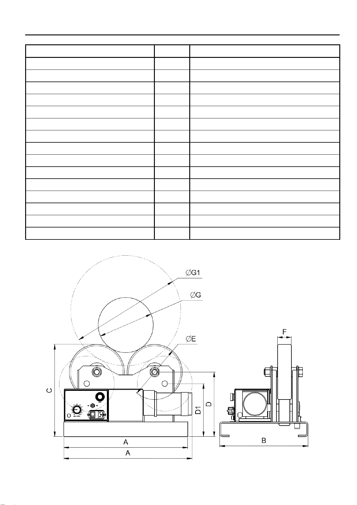
Diameter range (G / G1) mm ψ20 ~ψ500 /ψ400 ~ψ800
Roller type PU
Roller Diameter (E) mm ψ200
Roller width (F) 50
Overall length (A) (Drive / Idler) mm 470 / 450
Overall width (B) (Drive / Idler) mm 320 / 160
Overall height (C) mm 334
Roller center to base (D / D1) mm 234 / 192
Net weight (Drive / Idler) Kg 54 (37 / 17)
Gross weight Kg 58
2
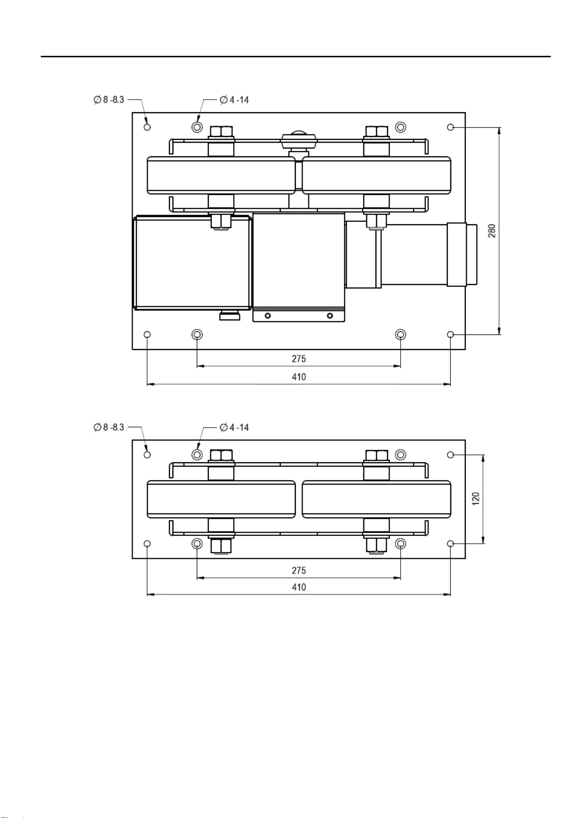
1. SPECIFICATION
3
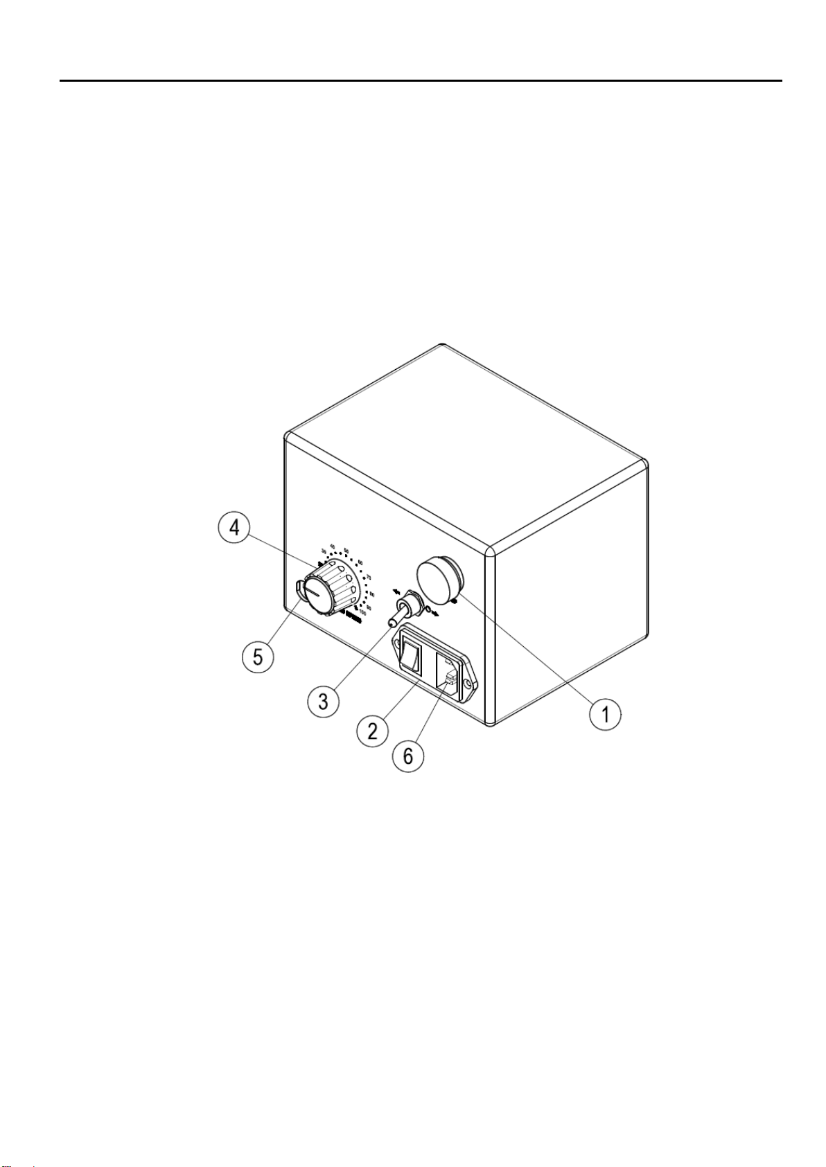
2.1 CONTROL PENAL
Operation Penal
1. Stop button.
2. Power socket.
3. Forward / Reverse switch.
4. Speed adjustment knob.
5. Foot switch.
6. Power cord.

4
2.2 INSTALLATION / OPERATION
1. Power cord:
Connect power to 100V~240VAC single phase power.
2. Power switch (SW1):
I = On,O = Off
3. Forward / Reverse switch (SW2):
Reverse ( ) / Forward ( )
4. Stop:
Press the Stop button to pause all motion and disable all control.
Rotate the Stop button clockwise to reset.
5. Speed Adjustment Knob (VR1):
Rotate clockwise to increase speed, counter clockwise to decrease speed.
6. Foot switch (F.S):
The foot switch is alternative type switch pressing it once and release would activate the roller.
Pressing it the second time to stop the roller.
7. Fuse holder (Fuse):
Overload protection.
5
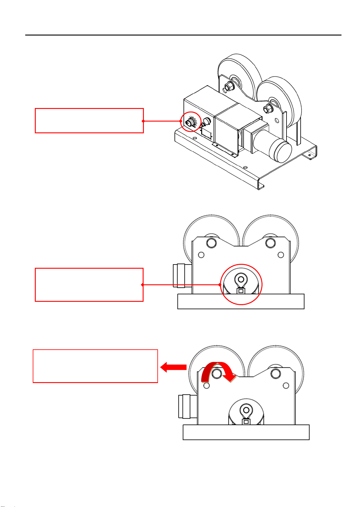
2.3 MAIN WHEEL ADJUSTMENT PROCEDURE
Step 1:
Step 2:
Step 3:
Use 17mm wrench and adjust
the nut in clockwise direction until
the PU roller moves.
Press the rollers with approximate
20-30 kg pressure and check for any
slip on the PU rollers.
Start the machine, then adjust
the speed to 50%.
6
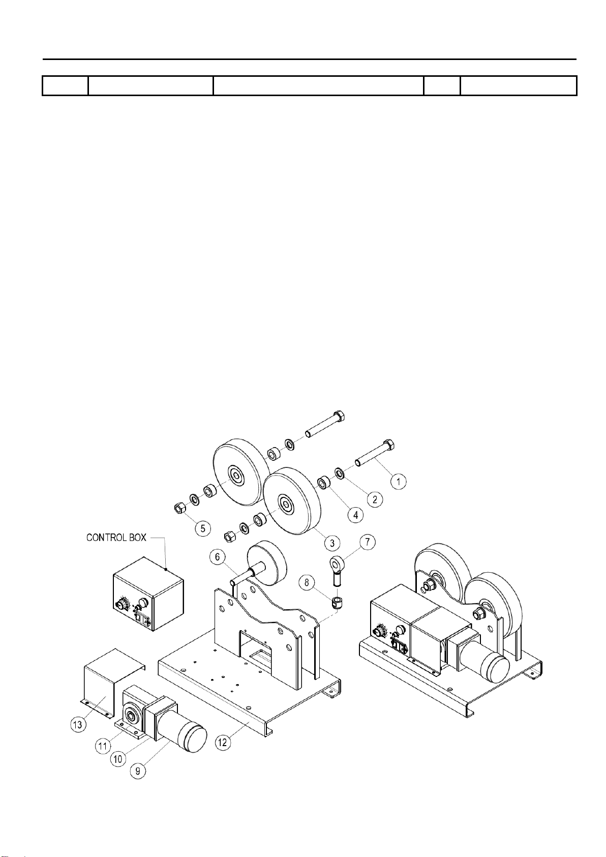
3.1 PARTS LIST ‒MAIN FRAME ( TR-0103P )
Item.
Part No.
Description
Q’ty.
Remark
1 5118-02271103030-10 Axle screw 2
2 0121-2000 Washer 4
3 5041-1030000-10 PU Wheel with bearing 2
4 5118-02271103040-10 Spacer 4
5 0123-2000 Hex Nut 2
0222-2000 Washer 2
6 5041-1020000-10 Main drive wheel 1
7 0311-2001 Joint bearing 1
8 5118-02271104020-10 Internal Stud 1
9
0361-1002-9
PMDC Motor & connector
1
10 0351-0109 Gear reducer 1
11 0352-0501 Worm gear reducer 1
12
5118-02271101000-11
Main wheel assembly
1
13 5118-02271106010-10 Motor cover 1
*Recommended spare parts

7
3.2 PARTS LIST ‒MAIN FRAME ( TR-0103 I )
Item. Part No. Description Q’ty. Remark
1 5041-1030300-10 Axle screw 2
2 5041-1030400-10 Spacer 4
3 5041-1030000-10 Roll unit (PU wheel + bearing ) 2
*
5041-1030100-10 PU wheel 2
*
0301-0403 Deep-groove ball bearing 4
4 0121-2000 Washer 4
5 0124-2000 Nylon insert lock nut 2
6 5118-02271115000-11 Idler wheel assembly 1
*Recommended spare parts
8
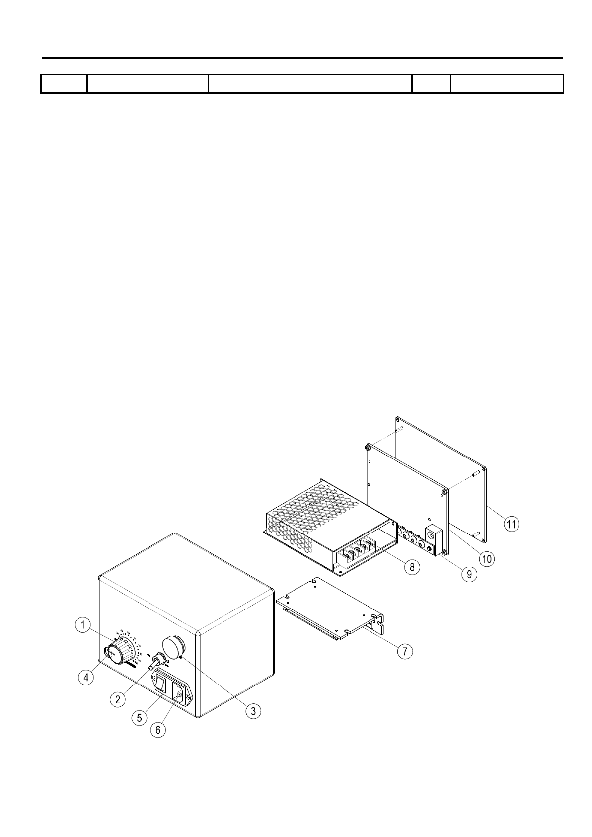
3.3 PARTS LIST — CONTROL BOX
Item.
Part No.
Description
Q’ty.
Remark
1
3216-0006 Knob 1 VR1
3747-1001
Potentiometer
1
2
3213-4007 Toggle switch 1
3
3214-2009
Push button
1
4
3242-1118 Foot switch 1 F.S
5
3445-2009
Power socket
1
6
3445-0001 AC Power cord 1 Option (Standard)
3456-0003 AC Power cord 1 Option (European)
3456-0004 AC Power cord 1 Option (Australian)
3456-0005 AC Power cord 1 Option (U.K)
7
*
6651-1010-1
Printed circuit board
1
8
3326-0008 Power supply 1 P.S
9
3545-5001
Grounding copper bar
1
10
5118-02271413000-10 Control box electrical panel 1
11
5118-02271412000-10
Control box cover
1
*Recommended spare parts
9
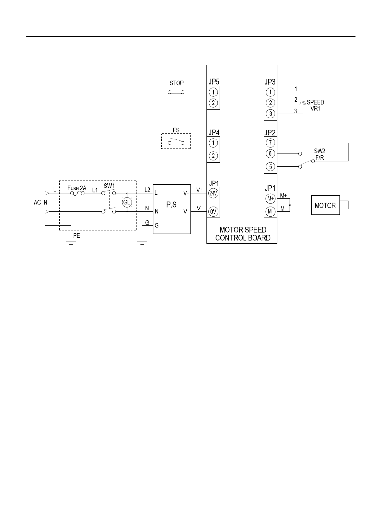
4. CICUIT DIAGRAM
This manual suits for next models
1
Table of contents
Other ProArc Welding Accessories manuals


