PRODEM PHC 050 User manual

Operation and Maintenance Manual
Plate Compactor
PHC 050
PHC 100
PHC 150
PHC 200
PHC 300
Parts No.: AA099-0053
Revision Date: 2011-12-15
©ProDem.

- 2 -
Foreword
WARNING!
It is very important for you to read and understand this manual before operating and to keep
the instructions provided herewith. Never fail to follow the instruction related to safety.
This manual contains instructions and information on safe and correct use of PRODEM Compactors.
Please read and understand this manual before operation, inspections and maintenance of the compactor.
Keep this manual with your equipment all the time for your quick and easy reference, and read it regularly.
Do not operate the compactor until you have been trained in the use of all operating controls and
understand the hydraulic compactor operation.
Get a replacement manual from PRODEM dealer if you lost it.
If you transfer the compactor to the other, do transfer this manual as well.
The figures in this manual is for better understanding and may not correspond exactly to the compactor.
For exact shape, refer to the parts list or ask PRODEM.
For the purpose of constant product improvement, some parts of this manual may be changed. If you
found the parts unclear or not corresponding to the compactor, call and consult PRODEM dealer or
service center
Important information on safety is described in the safety information chapter of this book. Be familiarized
with the instructions on the safe operation and observe the instructions before and during operation
Injury, death or damage caused by unauthorized product modifications and operation under unallowed
application will not be responsible by PRODEM. Consult PRODEM for such modifications and
applications.
Use PRODEM genuine parts. PRODEM takes no responsibility for damages caused by use of non-
PRODEM spare parts.
For warranty, we refer you to the warranty conditions provided separately.
We always exert all our efforts for your satisfaction, and promise you quick and constant service.
We thank you for using PRODEM compactor and wish you a good luck in every your job,
Dec. 2011
PRODEM Corp.
Copyright © 2011 PRODEM Corp. All rights reserved.
This manual is copyrighted by PRODEM Corp. with all rights reserved in accordance with prevailing law. It is
positively prohibited to use or reproduce its contents in whole or in part without prior written permission.

- 3 -
TABLE OF CONTENTS
Foreword..................................................................................................................................................................2
TABLE OF CONTENTS...........................................................................................................................................3
1. Safety Information................................................................................................................................................4
1.1. BASIC SAFETY INSTRUCTIONS...............................................................................................................5
1.2. PREPARATIONS FOR SAFE OPERATION................................................................................................6
1.3. Safety information for operation ..................................................................................................................7
1.4. Safety instructions for maintenance ............................................................................................................8
2. Product information..............................................................................................................................................9
2.1. Product configuration ..................................................................................................................................9
2.2. Product features........................................................................................................................................10
2.3. Specifications ............................................................................................................................................ 11
3. Installation..........................................................................................................................................................13
3.1. Installation of the piping.............................................................................................................................13
3.2. Installation of the compactor......................................................................................................................15
4. Operation...........................................................................................................................................................17
4.1. How to use compactor...............................................................................................................................17
4.2. Correct working mothod............................................................................................................................18
5. Service and maintenance...................................................................................................................................20
5.1. General guidelines ....................................................................................................................................20
5.2. Daily inspection.........................................................................................................................................20
5.3. Gear oil inspection and oiling ....................................................................................................................21
5.4. Maintenance instructions...........................................................................................................................21
5.5. Tightening torques.....................................................................................................................................23
5.6. Troubleshooting.........................................................................................................................................24
5.7. Dismounting and storing............................................................................................................................25

- 4 -
1. Safety Information
This manual describes correct use of the product and safety messages. Important or certain instructions in
this manual are marked with symbol. When you see this symbol provided in the manual or on the
product, be alert to the possibility of personal injury or death. Be sure to observe the instruction in the safety
message.
The safety messages in this manual do not describe all the possibilities of personal injury or death or of
damages to the product. This safety manual and the marks with symbols are intended to provide some of
basic instructions for safe operation, inspection and maintenance. It is operator’s responsibility to observe
the safety instructions and regulations though this manual does not include all the possible situations.
Remember! Safety is up to you
Safety Alert Symbol
The Safety Alert Symbol represents that
ATTENTION
is involved.
If you see the mark in this manual or on the products, never fail to read and
observe the instructions for safe operation.
Signal Words
The words “DANGER”, “WARNING”, “CAUTION” and “IMPORTANT” appeared with the above Safety Alert
Symbol indicate degree of risk of hazards or unsafe practices. All four degrees of risk indicate that safety is
involved. Observe precautions indicated whenever you see the Safety Alert Symbol, no matter which signal
word appears next to the “Exclamation Point” symbol.
DANGER! Indicates imminent hazard of a situation that, if not avoided, is very likely to cause
death or extremely serious injury. It may also be used to alert against product that
may exploded or detonate if handled or treated carelessly.
WARNING!
Indicates potential of a hazardous situation that, if not avoided, could result in serious
injury or death. It may also be used to alert against a highly unsafe practice.
CAUTION! Indicates potential of a hazardous situation that, if not avoided, could result in minor
or moderate injury. It may also be used to alert against a general unsafe practice.
IMPORTANT!
Indicates potential of damages that, if not avoided, could caused to the product or
shorten the product life.

- 5 -
1.1. Basi safety instru tions
WARNING!
The following instructions are those that should never be fail to observe in operation of
construction equipment.
Know yourself
All the operators and service men must wear safety equipment
required, hearing protection, respirator, hard hat, safety shoes, eye
protection glass, heavy gloves and other necessary equipment.
Wearing loose clothing or any accessories such as flopping cuffs,
dangling neckties and scarves, untied shoe-laces, rings, wrist
watches and long hair could be the cause of personal injury or
death.
Use the proper tools for inspection or maintenance work, which
must be carried out after ensuring the equipment stops completely
and is placed stably in the safe place
Figure 1
Know your equipments
Never fail to read and understand the safety messages, operation
manual and maintenance manual before installation and operation
of the compactor. The operator who has been trained and licensed
should only operate the carrier and the compactor. Familiarize
yourself with the operating especially safety related devices such
as safety lock, emergency stop and the others.
Figure 2
Know the work site
Before beginning operation, check in and around the work site for
any unusual conditions that could be dangerous and prepare the
appropriate warnings for safe work.
Be careful, especially when work in the vicinity of electric power
line, buried gas lines or oil tank. And pay your careful attention to
the people and the cars reside and passing near to the work site.
Prepare for every possible injury and damages.
Figure 3
Know the rules
Every people who operate or maintain the equipment should know
the meaning, rules and laws in terms of equipment handling. They
should know also the traffic rules, fire service act, emergency
measures and where the relief equipment is.
Keep the fire extinguisher and the first aid case in the operator’s
cabin for emergency use.
Figure 4

- 6 -
1.2. Preparations for safe operation
WARNING!
The following section describes the matters that must be prepared and checked in advance
for safe use of the compactor. Make yourself familiar with and keep the following instructions.
Install to a suitable arrier.
The excavator to which compactor is to be mounted should be selected based on the compactor capacity,
the mounting dimensions and the hydraulic device specification. If equipment that does not comply with the
prescribed specification is used for the compactor, either the compactor or the equipment may be damaged
or its life may be shortened. So, be sure to mount the compactor to the specified excavator. For matters
concerning the equipment selection, contact us or our sales representative.
Safety Guidelines for Installation
Install the compactor to the arm and link of the excavator, using mounting pins. The excavator operator and
the mounting worker should pay special attention, and agree on details and sequence of the work and
determine hand signals in advance. The operator should run the excavator as slowly as possible and the
worker should keep a safe distance and should keep his hands off from the excavator arm or link while the
excavator works. After assembling the mounting pin, tighten the bolts firmly, so that the pin may not get loose
during work.
When installing a pipe for mounting the compactor, follow our pipe installation specification. When
connecting a hydraulic hose, connect it with the specified connection torque and check if the hose is
completely connected before starting the excavator. If a sudden pressure is applied when the connection is
incomplete, the hose may sway to cause personal injury.
For more information about piping and pipe installation, see “3. Installation” in this Manual.
Inspe t the equipment before work.
Carefully inspect each checkpoint of the compactor and the
excavator before starting work. Check everything related to
safety such as equipment damage (breakage, crack, wear and
tear, deformation, etc.), part connection state and oil leakage
according to the check items specified in the operation manual
and that of the excavator. In particular, focus on checking if
there is any crack in the welded parts on the compactor body,
if bolts/nuts in each joint are loose, pin fixing state and
leakage from cylinder and hose.
If there is any problem in the compactor or in the excavator,
do not operate the excavator until proper maintenance work is
done. In this case, attach a warning tag to the equipment
driver seat so as to inform other people clearly of the
equipment status. It is desirable that the same person who
attached the warning tag removes it in person.
Figure 5

- 7 -
1.3. Safety information for operation
WARNING!
The following is the safety guidelines especially focused on using the compactor. Follow
these guidelines and refer to “4. Operation” for detailed information.
Never operate in unallowed appli ations
Do not carry out dangerous works that are not allowed in this manual. Improper operation of the compactor
could result in serious injury or death. For a correct method for using the compactor, see “4.2 Correct
Working Methods”.
Do NOT use for on rete or bedro k
Operating the compactor on the hard object such like concrete or bedrock will cause damage to the
compactor. Use the compactor only for soft objects.
Do NOT use for breaking or transport
Hammering or ramming with the compactor body to break a object or transporting a heavy object using the
compactor may damage the product and shorten its life, so it is absolutely prohibited.
Do NOT use under water
Never use the compactor in or under water. Operating the compactor under water will cause serious damage
to the cushion rubber.
Do NOT support arrier with ompa tor
Do not support the carrier using the compactor body, or do not apply excessive force to it.
For piling work, always use pile- lamp
When operating in piling work - driving-in or pull-up, always use the optional pile-clamp for safety. Piling
without the pile-clamp can bring out the risk of falling down of piles.
Do NOT use for rane work
This product is not equipped with safety devices for crane work. So, never perform crane work with this
product.
Stop working if any problem is found
If the compactor shakes unusually or there is abnormal vibration and/or noise during work, stop operating
immediately. In addition, if oil leakage from hose connections or any loose pin or joint is detected during the
operation, stop the compactor and check the problem.
- 8 -
1.4. Safety instru tions for maintenan e
Follow the manual
Follow the instructions in the manual for inspection and maintenance. In
particular, pay special attention to safety alerts and do not rush. Accidents
during maintenance are mostly attributed to negligence of the guidelines.
Figure 6
Completely stop the arrier
Inspection and maintenance should be done, after completely stopping the excavator on an even and safe
surface, with all control levers and switches on safe position.
Use proper tools
Use proper tools for inspection and maintenance. If you carry out any inspection or maintenance work using
improper tools, it may result in personal injury or damage to product.
Pay attention to hydrauli system
Draw special attention to maintain hydraulic system. Even though it is stopped,
the inside of a hydraulic system that has been operated can be hot. So, do not
disassemble it rashly. Be sure to remove the pressure left inside the hydraulic
device, close the lock and prevent any external forces from being applied to the
device according to a maintenance guide, before maintain it. For the compactor
cylinder in particular, there may be pressure left in the system even after the
compactor stops, and it may be exploded when it is disassembled. Therefore, be
sure to follow the disassembly order.
If there is a tiny hole or crack in the hydraulic device, pressurized fluid may
spout from it, to injure people near it. Fluid that spouts lightly may not be seen
by the naked eye. In this case, check the leakage using a sheet of paper or a
wooden board, wearing eye protection.
Right after operation, fluid is very hot. So, you have to be careful not to get
burned. In addition, as air inside the oil tank of the excavator is compressed, a
large amount of hydraulic oil may gush out if the hydraulic line connected to the
oil tank is disassembled. So, open the filler-cap slowly to remove the
compressed air from the oil tank before disassemble the hydraulic device.
Figure 7
Remove oil from the floor
When there is oil on the floor, it may result in an accident. So, when you spill or drop oil on the floor, wipe it
out immediately
.
Do not alter or modify
Unauthorized product modification or attachment of any unauthorized accessories can cause very dangerous
accidents. In addition, use of non-genuine parts can result in accidents or product damages. Therefore, use
our genuine parts only.

- 9 -
2. Produ t information
2.1. Produ t onfiguration
Mounting Plate
Upper Frame
Base Frame
Drive Casing Compacting Plate
Motor Control Valve
Motor
'P' Port
(IN) 'T' Port
(OUT)
Cushion Plate
Figure 8
The product configuration may vary depending product model.
Functions of the major parts
are as follows
Upper frame and base frame are the structures that form upper and lower parts of the Compactor
body.
In Drive casing, drive axis with eccentric weight which generates compacting force and bearings
that support the axis are assembled.
Motor (hydraulic motor) rotates at high speed by pressurized hydraulic oil from the carrier, to drive
the eccentric axis, and the vibration and centrifugal force induced by the rotation of the eccentric
weight generates compacting force.
Motor control valve is a built-in integrated valve to protect the hydraulic motor. There are two type
of the motor control valve; ‘N’ type valve has the reverse-flow-bypass and anti-cavitation functions
and ‘P’ type valve includes flow and pressure control function in addition to the standard features of
the ‘N” type valve.
Compacting plate contacting the ground compacts soil and make surface flat.
Cushion rubbers (cushion plates) is parts that help get effective compacting force from the
centrifugal force generated from eccentric weight and protect the carrier and operator by dampening
the vibration during compaction work.
Mounting plate is used to mount the compactor to the carrier using a mounting adapter.
’P’ port (IN) and ’T’ port (OUT) are connection ports to connect with piping of the carrier.
Components supplied
at the time of delivery are:
Compactor Assembly
Standard tool kits
User’s Manual, Parts List,
Hose and Fitting Set (Optional)
Mounting Adapter and fasteners set
(Optional, for Adapter Mount Type only)
Piping Kit (Optional)
(Components of the piping kit vary with
the carrier model.)

- 10 -
Compactor verson code
Version Code NA PA ND PD
Motor
Control
Valve
‘N’ Type Valve:
Reverse-flow-bypass and anti-cavitation
‘P’ Type Valve:
Flow and Pressure control
Reverse-flow-bypass and anti-cavitation
Bracket Adapter mount type
Direct mount type
2.2. Produ t features
High compacting productivity
PRODEM’s hydraulic plate compactor guarantees high compacting productivity by means of powerful impulse force.
Easy and versatile mounting
Adapter Mount: Flat top frame allows for installation on any carriers using a standard or custom made mounting
adapter.
Direct Mount: The frame is designed to accept a variety of slip-fit bushings and pins, resulting in versatile
installation on any carrier.
Firm and safe hose array
All Hoses are routed within the frame and connected to a mono hose block located on the frame. It protects the hoses
from damage and make it easy to connect the hoses.
High quality cushion rubber
Specially designed high quality cushion rubbers dampens vibration effectively and thus protect carrier and operator
from the vibrations.
Heavy duty gear motor and bearings
Heavy duty and high efficiency gear motor with splined shaft and self-aligning double row spherical roller bearings
provides a long service life of the rotating components and prevent possible damage caused by pressure shock
during start-up and shut-down.
Easy maintenance
Every part of the compactor is very easy to access for the maintenance.
Motor with built-in cross-check valve
Built-in cross-check valve within the hydraulic motor eliminates the need of a additional drain line, thus provides great
versatility for using general 2-line plumbing. And it also protects the motor shaft seal from damage caused by internal
oil leak of the motor.
Standard motor control valve (Reverse-flow-bypass and anti-cavitation check)
Built-in high flow check valve within standard motor control valve (‘N’ type valve) protects the motor from damage
caused by unintentional reverse connection of plumbing and cavitation induced by abrupt shutdown of hydraulic flow.
Optional motor control valve (Flow & pressure control)
Flow control valve (Pressure compensated priority flow divider) regulates hydraulic in-flow to the motor not to
excess the permissible maximum flow of the motor to prevent it from over-speeding. Thus, the compactor can be
installed on a carrier not equipped with a flow control valve on its auxiliary plumbing. And, it also control the motor
speed regardless of load pressure to generate the maximum compacting force continuously.
Pressure relief valve is also incorporated in the optional valve pack and it prevents system from over-pressure to
protect the motor. An attachment, such as breaker, which works at a relatively higher pressure than compactor can be
easily switched to the compactor on the same auxiliary plumbing without re-setting of the carrier’s relief valve
pressure.
All the valves; flow control, pressure relief, and reverse-flow-bypass & anti-cavitation check valves are packed within
the single mono valve block (‘P’ type valve).

- 11 -
2.3. Spe ifi ations
Adapter Mount Type Direct Mount Type
L
H
W
'P' Port
(IN) 'T' Port
(OUT)
LW
H
'T' Port
(OUT)
'P' Port
(IN)
Figure 10 Figure 11
Model PHC 050 PHC 100 PHC 150
Impulse Force
t
onne
(
klbs)
2.1
(4.6)
4.0
(8.8)
6.4
(14.1)
Weight
1)
A
dapter mount type(N*)
kg
(lbs)
260
(573)
A
dapter mount type(G*)
kg
(lbs)
280
(617)
430
(948)
689
(1,519)
D
irect mount type (N*)
kg
(lbs)
264
(582)
D
irect mount type (G*)
kg
(lbs)
344
(759)
Height (H)
1)
A
dapter mount type(N*)
mm
(
in.)
650
(25.6)
A
dapter mount type(G*)
mm
(
in.)
675
(26.6)
640
(25.2)
750
(29.5)
Direct mount type
(N*)
mm
(in.)
695
(27.4)
Direct mount type
(G*)
mm
(in.)
720
(28.3)
Width (W) (N*) mm
(
in.)
320
(12.6)
Width (W) (G*) mm
(
in.)
500
(19.7)
610
(24.0)
740
(29.1)
Base Plate
Dimensions (W x L) (N*) mm
(
in.)
320
x
745
(12.6 x 29.3)
Dimensions (W x L) (G*) mm
(
in.)
500
x
800
(19.7 x 31.5)
6
1
0
x
90
0
(24.0 x 35.4)
740
x
1,05
0
(29.1 x 41.3)
Compaction Area (N*)
m
2
(
ft
2
)
0.24
(2.6)
Compaction Area (G*)
m
3
(
ft
3
)
0.40
(4.3)
0.55
(5.9)
0.78
(8.4)
Oil Flow
w
ith 'N' type valve
l
pm
(gpm)
5
0 ~
72
(13.2 ~ 19.0)
80
~
116
(21.1 ~ 30.6)
w
ith 'P' type valve
2)
l
pm
(gpm)
45
~
65
(11.9 ~ 17.2)
5
0 ~
120
(13.2 ~ 31.7)
80
~
170
(21.1 ~ 44.9)
Max. Cycles Per Minute
r
pm
2,100
2,000
2,000
Operating Pressure
F
ree load
bar
(psi)
3
0 ~ 50
(440 ~ 730)
3
0 ~ 50
(440 ~ 730)
3
0 ~ 50
(440 ~ 730)
With load bar (psi) 100 ~ 220 (1,450 ~ 3,190) 100 ~ 138 (1,450 ~ 2,000) 100 ~ 138 (1,450 ~ 2,000)
Recommended Carrier
t
onne
(ton)
4 ~ 6
(4 ~ 7)
6 ~ 10
(7 ~ 11)
1
1
~
16
(12 ~ 18)
Weight
Recommended Hydraulic mm
(
in.)
12.7
(1/2)
19
(3/4)
19
(3/4)
Line Size (In / Out)
Max. Acceptable Back bar (psi) 15 (220) 15 (220) 15 (220)
Pressure
Max. Pressure Relief bar (psi) 220 (3,190) 138 (2,000) 138 (2,000)
Type of Hose Connection Ports
BSP
1/2
O-Ring Boss Female
BSP
3/4
O-Ring Boss Female
BSP
3/4
O-Ring Boss Female
(JIS B2351 Type 'O')
(JIS B2351 Type 'O')
(JIS B2351 Type 'O')
Available Fitting Set
O
RFS -8
3)
O
RFS -12
3)
O
RFS -12
3)
B
SP 1/2 (60º Cone)
4)
B
SP 3/4 (60º Cone)
4)
B
SP 3/4 (60º Cone)
4)
J
IC -8
5)
J
IC -12
5)
J
IC -12
5)

- 12 -
Model PHC 200 PHC 300
Impulse Force
t
onne
(
klbs)
11.2
(24.7)
17.3
(38.1)
Weight
1)
Adapter mount type(N*) kg (lbs)
Adapter mount type(G*) kg (lbs) 1,094 (2,412) 1,502 (3,312)
D
irect mount type (N*)
kg
(lbs)
Direct mount type (G*) kg (lbs)
Height (H)
1)
A
dapter mount type(N*)
mm
(
in.)
Adapter mount type(G*) mm (in.) 840 (33.1) 943 (37.1)
Direct mount type (N*) mm (in.)
Direct mount type (G*) mm (in.)
Width (W) (N*) mm
(
in.)
Width (W) (G*) mm (in.) 860 (33.9) 1,000 (39.4)
Base Plate
Dimensions (W x L) (N*) mm
(
in.)
Dimensions (W x L) (G*) mm (in.) 860 x 1,200 (33.9 x 47.2) 1,000 x 1,300 (39.4 x 51.2)
Compaction Area (N*) m
2
(ft
2
)
Compaction Area (G*) m
3
(ft
3
) 1.03 (11.1) 1.30 (14.0)
Oil Flow
with 'N' type valve lpm (gpm) 110 ~ 162 (29.1 ~ 42.8) 160 ~ 220 (42.3 ~ 58.1)
with 'P' type valve
2)
lpm (gpm) 110 ~ 200 (29.1 ~ 52.8) 160 ~ 250 (42.3 ~ 66.0)
Max. Cycles Per Minute rpm 2,000 2,000
Operating Pressure
F
ree load
bar
(psi)
3
0 ~ 50
(440 ~ 730)
3
0 ~ 50
(440 ~ 730)
With load bar (psi) 100 ~ 138 (1,450 ~ 2,000) 100 ~ 138 (1,450 ~ 2,000)
Recommended Carrier tonne (ton) 17 ~ 25 (19 ~ 28) 26 ~ 40 (29 ~ 44)
Weight
Recommended Hydraulic mm (in.) 25 (1) 32 (1-1/4)
Line Size (In / Out)
Max. Acceptable Back bar (psi) 15 (220) 15 (220)
Pressure
Max. Pressure Relief bar (psi) 138 (2,000) 138 (2,000)
Type of Hose Connection Ports
BSP
1
O-Ring Boss Female
BSP
1-1/4
O-Ring Boss Female
(JIS B2351 Type 'O')
(JIS B2351 Type 'O')
Available Fitting Set ORFS -16
3)
ORFS -20
3)
B
SP
1
(
60
º Cone
)
4)
B
SP
1
-
1
/
4
(
60
º Cone
)
4)
JIC -16
5)
JIC -20
5)
Notes: 1) Excluding mounting adapter, hydraulic hoses, fittings and mounting pins.
2) Standard settings at the factory. Other extra flow ranges are also available on request.
3) The O-Ring Face Seal (ORFS) type hose coupling according to SAE J1453
4) The 60º cone type hose coupling according to JIS B8363 (hoses with 60º male sealing face)
5) The 37º flare type hose coulping according to SAE J514
6) PHC 050: (N*)-Narrow type, (G*)-General type
- 13 -
3. Installation
3.1. Installation of the piping
CAUTION!
Inappropriate piping may result in damaging the compactor or carrier and shortening of its life.
Be sure to follow our regulations on pipe installation.
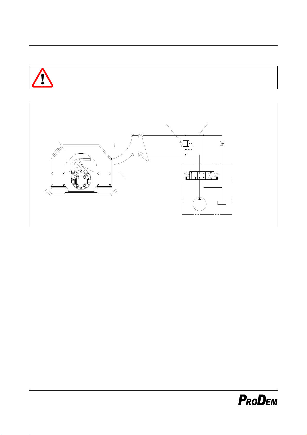
Hydraulic Circuit Diagram (recommended)
Compactor
'P' Port
(IN)
'T' Port
(OUT)
Stop Valve
Relief Valve
(See ※)
Drain line
(necessarily required)
Stop Valve for
by-directional
operation
(option)
★ Carrier's hydraulic systemmay vary depending
on the model and maker.
P
T
PT
AB
Figure 12 The above circuit diagram is for reference only.
The specifications of carrier’s hydraulic system required to operate the compactor is as follows.
Pump Flow: Higher than the minimum working flow of the compactor
System Pressure: 180 bar or higher
Allowable Back-Pressure: 15 bar or less
Compactor piping is basically the same as breaker piping, and thus it is possible to use the breaker piping
as it is without any modification.
★But, the drain(low-pressure) line must be connected directly to oil cooler or oil tank.
If the drain line is connected to the control valve of the carrier, the compactor’s motor can be
damaged.
If the drain line of carrier has a stop valve for by-directional operation, be sure to operate the compactor
with opening the stop valve.
The drain line should has sufficiently large inner diameter to meet the specified maximum acceptable
back-pressure of the compactor. If the back pressure – measured at the ‘T’ port during operation – is
higher than the specified value, check the inner diameters of pipes, hoses or fittings of the drain line.

- 14 -
Setting and Adjusting Relief Valve (※
※※
※)
For the compactor with ’N’ type valve, a relief valve must be installed to compactor piping, and must be
adjusted to the specified maximum operating pressure ot the compactor.
For the compactor with ‘P’ type valve, you do not need to install a relief valve to compactor piping. If a
relief valve has already been installed for other attachment, such as breaker, you do not also need to re-
adjust the setting pressure according to the compactor’s operating pressure.
Please consult PRODEM or our dealer for more detail about the compactor piping.
Piping should be placed as follows when the compactor is viewed from the operator in carrier’s cab:
P Line (IN) : Left
T Line (OUT) : Right
When ‘P’ and ‘T’ lines are reversed with each other, the compactor does not work or rotate very slowly by
means of the reverse-flow-bypass check valve of the motor control valve to protect the hydraulic motor.
So, make it sure that piping is installed in right direction.
When you newly install piping, make it sure that there is no foreign substance inside piping sub-parts
such as hoses, pipes, valves and fittings. After finishing installation of piping, connect ‘P’ and ‘T’ line
directly to each other without connecting the compactor and do flushing process during minimum 5
minute to make hydraulic oil clean before connecting the hoses to the compactor.
Be sure to use piping parts that conform to the hydraulic specification of the compactor and carrier. When
using the compactor with the piping modified for other purpose or modified with parts whose configuration
has not been confirmed, be sure to consult our service or dealer. Remember that problems resulting from
wrong piping or wrong installation are not covered by our warranty.
- 15 -
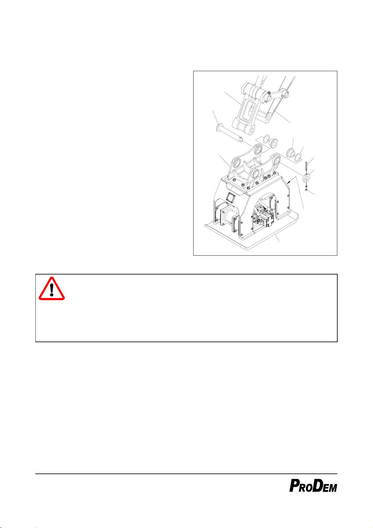
3.2. Installation of the ompa tor
Mount the compactor to the carrier as following;
1. In case of adapter mounting type (‘NA’ or ‘PA’
version), assemble a mounting adapter to the
compactor as shown in Figure13.
2. Place the carrier and compactor on flat and firm
ground in the direction as shown in Figure 13.
3. Assemble the spacers and shims to the bores
of the mounting adapter.
The dimensions of the spacers and the number
of shims may vary depending on carrier’s
mounting dimensions, such as the pin diameter
or the width of the arm or link.
4. Move carrier’s arm slowly until its pin-bore is
flush with the pin bore of the mounting adapter,
and insert the mounting pins.
5. Assemble the stop-rings, and tighten bolts and
nuts to fix the mounting pins.
6. Then, assemble the mounting pin for carrier’s
link in the same way as for carrier’s arm.
Arm
Link
Spacer
Shim
Mounting
Pin
Mounting
Adaptor Bolt
Stop
Ring
Nuts
Compactor
Hose
Connector
(P/T)
Figure 13
DANGER!
When moving the carrier, do not touch any part of the carrier. Keep hands away from linkage
area and pin-bores of the carrier.
When aligning pin-bores, never put a finger into the pin-bore, align only by sight or with using
drift pin.
Agree with the assistant on clear hand signals. The operator in the carrier’s cab should run the
carrier as slowly as possible. When the carrier is moving, workers should keep safe distance
from the carrier.

- 16 -
Connect the hoses to the carrier as follows;
1. After assembling of the mounting pins is completed, turn off the excavator completely.
2. Close the stop valves on the arm end, and remove caps.
3. Connect hydraulic hoses as shown in Figure 14. Make it sure that ‘P’ and ‘T’ lines are not reversed each
other.
4. When connecting the hoses, make it sure that no foreign substances get into the hoses. Dirt, sand or it
may cause a serious trouble to the compactor and carrier.
5. Arrange the connecting hoses not to be twisted or excessively bent.
Bucket Cylinder
Compactor Stop Valve
Cap
★
Pay attention to piping direction!
P Line (IN) : Left
T Line (OUT): Right
(in view from the driver's seat)
Figure 14
When all installation works are completed, check the followings before operating the compactor.
While moving the carrier’s bucket cylinder slowly in and out – in the direction of ‘crowd’ and ‘dump’,
check;
Any interference or obstruction between the compactor and carrier,
Whether the length of the connecting hoses are too short or too long,
Twisting, excessive bending or squeezing of the connecting hoses,
Fixing status of the mounting pins.
While operating the compactor with lifting up the compactor not to touch the ground (no-loading condition),
check;
Whether the compactor runs normally without delay when the operating switch is pressed ON, and it
stops when OFF.
Any oil leak from hoses, fitting, hydraulic motor or motor control valve,
Loosening of bolts or nuts,
Crack or tear out of the cushion rubbers,
Abnormal vibration or noise while the compactor running.

- 17 -
4. Operation
DANGER!
The following section describes a correct use and precautions for compactor operation. These
are the fundamentals for safe operation. So, make yourself familiar with them before initial
use.
IMPORTANT!
If you operate compactor, having it touched a solid ground such as concrete floor or a
bedrock, it would apply very high impact to the compactor, which might result in a serious
damage to the compactor.
4.1. How to use ompa tor
Place the compactor on the ground you want to compact to be in touch with it uniformly.
Lower the carrier’s boom slowly to press the compactor vertically to the ground. At this time, make it
sure that cushion plate is pressed less than 4 cm. If the cushion plate is pressed more than the
specified limit, it might be damaged or its life might be shortened.
If you operate the compactor, having it touched a very hard object such as concrete floor or bedrock,
it would apply very high impact to the compactor, which might result in a serious damage to the
compactor.
When the ground starts to be lowered by compacting work, lower the carrier’s boom gradually and
keep a constant applying pressure. At this time also, make it sure that the cushion plate is not pressed
too much.
When compacting a wide area, advance working positions sequentially in a uniform direction with
some overlapped area.
Mostly for normal soil condition, proper working time is 5 ~ 10 seconds at once.
Continuous operating for a long time have no more effect on compacting and, on the contrary, may
result in trouble to the compactor.
To obtain optimal compaction of the soil, repeat the compacting work in two or three passes. The
duration of compacting for the later pass can be shorten than initial pass.
★Do not use for the following objects:
Concrete floor
Bedrock or surface covered with stones
Steel plate
Press down in a
direction vertical
to the ground.
Continous
operating time
should be
limited to 10
seconds or less.
Cushion rubber
(Cushion plate)
Less than
4 cm
Figure 15

- 18 -
4.2. Corre t working method
IMPORTANT!
Figure 16
Keep vertical to the ground.
Operating the compactor with a tilt
to the ground surface –without
uniform contact to the ground–,
the compactor might be damaged.
Always keep the compacting plate
in parallel to the ground and press
it vertically to the ground.
IMPORTANT!
Figure 17
Do not transport using the
compactor.
Do not move or break a heavy
object using the compactor, which
may result in the compactor
damage or shorten its life.
IMPORTANT!
Figure 18
Do not support carrier with the
compactor.
Do not support the carrier using
the compactor body, and do not
apply excessive force to the
compactor.

- 19 -
IMPORTANT!
Figure 19
Do not use for unallowed
purpose
If the compactor is used for
unallowed purpose or harsh work
which apply exce
ssive force to the
compactor, both the compactor and
the carrier would be damaged and
their lives rapidly shortened.
DANGER!
Figure 20
Do not use for crane work.
The compactor is not equipped
with safety devices for crane work,
so it is very dangerous to use the
compactor for crane work. And
also, lifting a heavy object up with
the compactor will result in severe
damage and shortening of its life.
IMPORTANT!
Figure 21
Do not work under water.
The compactor should not be used
for underwater work. Operating the
compactor under water will cause
serious damage to the cushion
rubbers.

- 20 -
5. Servi e and maintenan e
IMPORTANT!
To use the product in its best condition without any troubles for a long time, observe the
following inspection and maintenance instructions.
In addition, be sure to follow the safety instructions in performing inspection and maintenance.
5.1. General guidelines
Be sure to do the following sequence prior to inspection or maintenance work:
1. Stop the carrier completely.
2. Shut off the stop valves.
3. When disconnecting the hoses, seal them with plugs or caps to prevent entry of impurities.
Whenever maintenance work is carried out, always follow the basic instructions of maintenance for your
safety and product life.
Use proper tools only. Using improper tools may cause personal injury or part damage.
Even after the carrier completely stopped, quite high hydraulic pressure may remain within the compactor.
Disassemble slowly with care.
All of the rotating parts assembled in the drive casing of the compactor are precise parts. Be sure to
handle them carefully, and keep them free of foreign substances or humidity.
Use only genuine parts. Use of unapproved parts may cause damage to the compactor or personal injury.
The troubles in this case voids the warranty.
Do not make any modification to the compactor. We do not take responsibility for accidents and product
damages resulting from unauthorized product modification.
Please contact PRODEM or our dealer for details regarding service and maintenance.
5.2. Daily inspe tion
To use the compactor for a long time in its best condition, do the following daily inspection and maintenance
job regularly.
CHECK POINTS RELATED PARTS ACTION
Tightening of Bolts and Nuts
All the bolts and nuts of
Cushion Plates, Motor, Covers, Valve,
etc.
Mounting adapter bolts
Retighten the loose one,
Replace the broken or worn parts.
Oil Leak
Hoses, Fitting or Plugs
Hydraulic Motor
Motor Control Valve
Retighten the loose one.
Replace damaged O-ring or seal.
Abnormal Noise or Vibration
during Operation
Hydraulic Motor
Bearings (in Drive Casing)
Cushion Plates (Cushion Rubbers)
Check oil level and inspecting after
refilling oil.
Contact PRODEM service if the
problem persists.
Breakage, Deformation, Crack,
or Wear and Tear
Base Frame and Mounting Frame
Cushion Plates (Cushion Rubbers)
Mounting Pins
Contact PRODEM service, if any
problem is detected.
Other manuals for PHC 050
1
This manual suits for next models
4
Table of contents
Other PRODEM Industrial Equipment manuals


