manuals.online logo
Brands
  1. Home
  2. •
  3. Brands
  4. •
  5. Autonics
  6. •
  7. Measuring Instrument
  8. •
  9. Autonics KRN1000 Series User manual

Autonics KRN1000 Series User manual

Input/Output
Input/Output Circuit
Universal input Communication output
Option input/output 1
(alarm output 8 channels)
Option input/output 2
(alarm output 6 channels + digital input 2 channels)
Option input/output 3
(alarm output 6 channels + power for transmitter output)
Option input/output 4
(alarm output 4 channels + digital input 2 channels
+ power for transmitter output)
󾖴󾖴󾖴󾖴󾖴󾖴󾖴󾖴󾖴󾖴󾖴󾖴
󾖴
Comprehensive Device Management Program [DAQMaster]
Error Message
 


󽗊

󽗊


󽗊

󽗊
 󽗊

 






  
 
 
 
 
 
 
 




 
 
 
KRN1000 04 0 1 0 S
Ordering Information
 󽗉  󽗉
   

  
   
Speci󽗉cations
Unit Description
 



 KRN1000
  
 
 

 
 
 
 
 

 
󽗉
 
 

 

  
 
 
 
 
 


 
 


1. Sensor input terminal: 
2. Ethernet port:

3. RS422/485 port:


4. Option input/output port:


5. Power input:
1. Power indicator:
2. Screen:
󽗉
3. Front cover:

4. Power switch: 
5. USB host port: 


6. USB device port:
7. SD card slot: 
8. Stylus pen:


Front part
Rear part
7
8
4
5
6
1
2
3
Dimensions 
 ● Bracket




 

● Panel cut-out
  

 



  


 
 
 

 



 




 




  
 


   
 
  
 


 
 
 



 









󽗈 



5
4
3
2
1
DRW190189AC
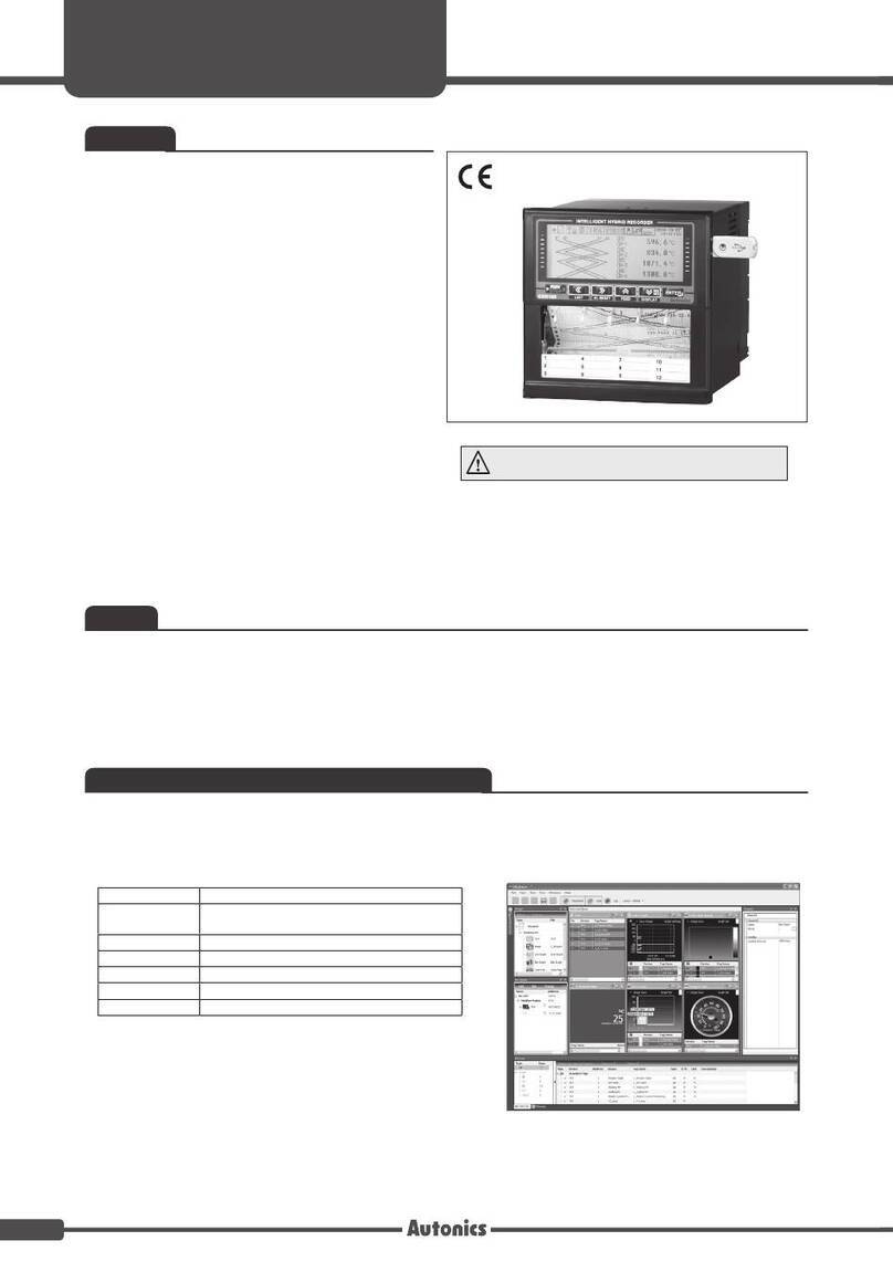
LCD Touchscreen Paperless Recorder
KRN1000 SERIES
Thank you for choosing our Autonics product.
Please read the following safety considerations before use.
I N S T R U C T I O N M A N U A L
※Please read Safety Considerations in KRN1000 user manual before using.
1. Fail-safe device must be installed when using the unit with machinery that may cause serious injury or substantial
economic loss. (e.g. nuclear power control, medical equipment, ships, vehicles, railways, aircraft, combustion apparatus,
safety equipment, crime/disaster prevention devices, etc.)
Failure to follow this instruction may result in personal injury, economic loss or re.
2. Do not connect, repair, or inspect the unit while connected to a power source.
Failure to follow this instruction may result in re or electric shock.
3. Check 'Connections' before wiring.
Failure to follow this instruction may result in re.
4. Do not touch the product during operation or for a certain period of time after stopping.
Failure to follow this instruction may result in burn or re.
5. Do not use the unit in the place where ammable/explosive/corrosive gas, high humidity, direct sunlight, radiant heat,
vibration, impact, or salinity may be present.
Failure to follow this instruction may result in explosion or re.
6. Install on the device panel or DIN rail, and ground to the F.G. terminal separately.
When connecting the F.G. terminal, use AWG16(1.25mm²) or over.
Failure to follow this instruction may result in re or electric shock.
7. Do not disassemble or modify the unit.
Failure to follow this instruction may result in re or electric shock.
8. Since Lithium battery is embedded in the product, do not disassemble or burn the unit.
Failure to follow this instruction may result in re.
Safety Considerations
Warning
1. Use the unit within the rated specications.
Failure to follow this instruction may result in re or product damage.
2. Use a dry cloth to clean the unit, and do not use water or organic solvent.
Failure to follow this instruction may result in re or electric shock.
3. Keep the product away from metal chip, dust, and wire residue which ow into the unit.
Failure to follow this instruction may result in re or product damage.
4. When connecting the power input or measurement input, use AWG20(0.50mm²) cable or over and tighten the terminal
screw with a tightening torque of 0.74 to 0.9N.m.
Failure to follow this instruction may result in re or malfunction due to contact failure.
5. Do not use the load beyond rated switching capacity contact.
Failure to follow this instruction may result in re, relay broken, contact melt, insulation failure or contact failure.
6. Use the transmitter output card only as the power for the transmitter.
Failure to follow this instruction may result in output module damage.
7. Do not put any heavy object on the front screen.
Failure to follow this instruction may result in malfunction due to deformation of LCD and touch panel.
Caution
※Please observe all safety considerations for safe and proper product operation to avoid hazards.
※symbol represents caution due to special circumstances in which hazards may occur.
Warning Failure to follow these instructions may result in serious injury or death.
Caution Failure to follow these instructions may result in personal injury or product damage.
User Manual
For the detail information and instructions, please refer to user manual and user manual for communication.
※The above specifications are subject to change and some models may be discontinued without notice.
※Be sure to follow cautions written in the instruction manual and the technical descriptions (catalog, website).
Autonics
-
CE:~
-
-0
-
---
-~-~-~
1
,
..
,
-·
,
--
-·
....
....
-
,,., ,,., ,,.,
....
....
,.,
..
,
... ...
....
- -
,,..
nu
,,.,
nu
HU
•-
.,,,_,
.....
-
.....
---
·=-
--
\
1• 1
-~
t -
'--
0
(Qi
• .
"iW""'·
:!'
n
0.
• 0
◄
Chann
■
I
I I
y11
I I I
II
A~
!
:.
I~}
(€
~~
1
~~~~
1
r=,
L J
•
~
□
0 =
=
I I
J
□
Iffi7
w
Cl
[B]A
-
!,BJ
~b'
-
!:]]~~
;b,]-$/S
RTD
TC
V
mA
Sensor
Analog
All
Al2
Al3
Al4
AlS
Al6
Al7
Al8
6m'm
~ffi'Tu
6ffi'm
§l@)J
24VDC OUT
(Max. 60mA)
All
Al2
Al3
Al4
Al5
Al6
~
r
6m'm
~ffi'Tu
6ffi'm
[§J
filJ
~
Ethernet
(10/100)
[a
All
Al2
Al3
Al4
AlS
Al6
r
r9
6m'm
~ffi'Tu
6ffi'm
~
~
rffi
24VDC
OUT
_ (Max. 60mA)
All
Al2
Al3
Al4
r
r9
~
r
f"''.::f
""-1
r°""'.::f
""-1
D11
DI2
COM
C+l C+l
C-l
ITJ
W0 0 W0 0 [!] [!]
~
fill
lg]
4) Memory Management [Menu → Memory Info. → Memory Management]
It manages internal/external memory. You can check memory usage and move and copy data files.
No Item Descriptions
1 Internal Memory Displays each memory usage.
Touch ‘Clear’ to initial the memory.
2 SD Memory
3 USB Memory
4 Move/Copy
Moves/Copies 󽗉les of internal memory to SD/USB memory.
- Move: Moves the 󽗉le to external memory and deletes the existing 󽗉le at internal memory.
- Copy: Moves the 󽗉le to external memory and maintains the existing 󽗉le at internal memory.
- Delete: Deletes the 󽗉le.
- Move All: Moves all 󽗉les to external memory and deletes the existing all 󽗉les at internal memory.
- Copy All: Moves all 󽗉les to external memory and maintains the existing all 󽗉les at internal memory.
- Delete All: Deletes all 󽗉les.
5Storage Select the memory to save the data.
1
4
5
2
3
Status Display Part
1 2 3 4 5 6 7 8
Section Item Description
1
Menu Displays menu.
Esc Moves from menu to current screen.
Home Moves to main screen.
2Group
Displays currently displayed group name.
Touch the icon and select the group. You can set the group name and the set
group name is displayed.
3Graph
Select the displayed graph at the current screen.
Select one among bar graph, vertical/horizontal trend graph, divided vertical/
horizontal trend graph, vertical/horizontal mixed graph, digital group/all.
4
Lock Displays at standard user mode.
(activated log-in function or log o󽗈 status)
Lock Setting Displays at administer mode.
(activated log-in function and log-in as administer mode)
Unlock Displays at unlock.
(inactivated log-in function)
No Alarm Displays at no alarm.
Alarm Displays when alarm occurs.
5
Internal Memory
Record
Displays when displaying measurement value and no recording it at internal
memory.
Internal Memory
No Record Displays usage details of data recording space.
6
Data Record Space Displays usage details of data recording space.
Alarm Record Space Displays empty space of alarm data memory.
Event Record Space Displays empty space of event data memory.
7
USB Memory
No Connection Displays when USB memory is not connected.
USB Memory No Save
(gray) Displays when internal memory data does not save at USB memory.
USB Memory Save
(yellow) Displays when internal memory data saves at USB memory.
SD Card
No Connection Displays when SD card is not connected.
SD Card No Save
(gray) Displays when internal memory data does not save at SD card.
SD Card Save
(yellow) Displays when internal memory data saves at SD card.
8Date/Time
Displays date and time.
If summer time is set, "(s)" marks in front of time.
Menu
3) File [Menu → System Info. → File]
It manages parameter setting files which are saved at KRN1000 memory, resets parameters.
No Item Descriptions
1Parameter
Setting File Displays parameter setting 󽗉le name.
2 Internal Memory
Save the set parameter information at the dedicated memory or open it.3 SD Memory
4 USB Memory
5 Reset Parameters Reset parameter settings as factory default.
6Screen Simulation
(Demo)
Execute simulation the set parameters.
Touch ‘Start’ and re-boot the unit and simulation mode starts.
Touch ‘Stop’ to exit simulation mode and re-boot the unit.
1
4
2
5
3
6
※For more information about menu, refer to KRN1000 user manual.
Cautions during Use
Display History
File History
Group Setting
Touch Calibration
Input CH Info. Input/Display
Input Option
Alarm
User Unit
Option Info. Alarm Output
Digital Input
RS422/485
Ethernet/USB
Status Alarm List
Event List
AO/DI Status
Screen Capture
Log OFF/Power OFF
Memory Info. Memory Management
Internal Memory
System Info. Date/Time
Reservation
Device
Log In
File
System Info.
It sets initial setting and option of KRN1000.
2) Device [Menu → System Info. → Device]
No Item Descriptions
1Device Name Set KRN1000 device name.
It supports English capital/small letter, sign and number up to 16 characters.
2Language Set KRN1000 display language.
It supports Korean, English, Chinese (Simpli󽗉ed/Traditional) and Russian.
3PWR ON Record
Set record status when supplying power or re-supplying power at power failure.
- Hold: It maintains record status (recording/stop) of before power OFF.
- Record: It records when power is ON.
- Stop: It does not record regardless when power is ON.
4Touch Sound Set touch sound volume when touching the menu or button of screen.
Setting range: OFF, Min., Standard, Max.
5Alarm Sound Set alarm sound volume.
Setting range: OFF, Min., Standard, Max.
6Sampling
Set internal sampling period of measurement value.
Setting range (varied by number of input channel connections)
- Below 4CHs: 25, 125, 250ms
- The others: 125, 250ms
7Log Record
Speed
Set log speed for recording measurement value at system memory.
Setting range: 1 to 3600 sec
E.g.) When setting as 3 sec, it records present value and the value after 3 sec.
8Graph Speed Set Graph speed for displaying data on the graph.
Setting range: 1 to 3600 sec
E.g.) When setting as 3 sec, new data is displayed on the graph with the interval of 3 sec.
9Backlight Set display backlight level.
Setting range: Min., Standard, Max.
10 Screen Save
For saving LCD life cycle and power, screen can automatically turn OFF.
Even though during screen save status, it maintains recording. Touch the screen and it turn ON the screen.
Setting range: 0 to 360 min (0: disable screen save)
1 6
4
27
38
5 10
9
Major Menu
1) Input/Display [Menu → Input CH Info. → Input/Display]
1
4
2
5
3
6
8
9
10
7
No Item Descriptions
1Channel Moves channel. Touch 'CH1' or to change the channel.
2Copy Copies the other channels parameters of the same group. Select the channel to be copy.
3Input Type Set the input type. Input types are total 27: thermocouple, RTD, voltage, current (shunt).
4Low-Limit Graph Scale/
Low-Limit Input
In case of temperature sensor input, set the low-limit graph scale value within the input range.
Setting range: Min. value of input range to high-limit graph scale value-F.S. 5%
E.g.) In case of TC-K input, -200.0 to 1350.0℃ of input range, and setting range is -200.0 to 1272.5℃.
(-F.S.=77. 5)
In case of analog input, it displays low-limit input value.
5
High-Limit Graph Scale/
High-Limit Input
In case of temperature sensor input, set the high-limit graph scale value within the input range.
Setting range: Low-limit graph scale value+F.S. 5% to Max. value of input range
E.g.) In case of TC-K input, -200.0 to 1350.0℃ of input range, and setting range is -122.5 to 1350℃.
(+F.S.=77.5)
In case of analog input, it displays high-limit input value.
6Point - Temperature sensor input: 0, 0.0 (set the decimal point for the measurement value)
- Analog input: 0, 0.0, 0.00, 0.000, 0.0000 (set the decimal point position for the scale value)
7Tag Name Set the channel name.
8Low-Limit Scale Set the desired display value based on the measurement value.
It is activated only for analog (voltage, current (shunt)) input type.
9High-Limit Scale
10 Display Unit - Temperature sensor input: Temperature units, ℃, ℉, K are available.
- Analog input: 72 display units are available. When not using unit, select blank.
It sets input type of each channel of KRN1000.
1. Follow instructions in 'Cautions during Use'. Otherwise, it may cause unexpected accidents.
2. Install a surge absorber at each end of inductive load coil when controlling high-capacity power relay or inductive load (e.g. magnet).
3. 24VDC power supply should be insulated and limited voltage/current or Class 2, SELV power supply device.
4. Check the polarity of the terminals before wiring the temperature sensor.
For RTD temperature sensor, wire it as 3-wire type, using cables in same thickness and length.
For thermocouple (CT) temperature sensor, use the designated compensation wire for extending wire.
5. Keep away from high voltage lines or power lines to prevent inductive noise.
In case installing power line and input signal line closely, use line lter or varistor at power line and shielded wire at input signal line.
Do not use near the equipment which generates strong magnetic force or high frequency noise.
6. Install the unit straightly at the well-ventilated environment with 30mm of separation distance from the wall.
7. This unit may be used in the following environments.
①Indoors (in the environment condition rated in 'Specications') ②Altitude max. 2,000m
③Pollution degree 2 ④Installation category II
Jl
• 1
111
,.
11
11
~
M u -
--
,
1/b-!
~r===;:J
enu
GROUP1
Bar
Graph
II
O ALARMlll'IIWIIII
~
2016/04/14
- , L
EVENT
.1.
-15,55:
I I
-
~
I • _I
-
-
ff]
r~1.~
~
~
i
~
1tr.11t,1i
I -
-1
1·
!!·!9~11
1I
111
11
~I,
,,,,
!
I
-1
!
l:.'ll
uss
-I
!l:,'ll
uss
-1
I
-1
llll
s:;,,
■
I
lllls:;,,
,,,
ill
-
-
•
'..
,
llill
USB
' --
"
""
··
··
1111--
Copy
~,
-S-e
le
-,-
, -I
Input Type I TC-K ]
Low
-L
imit Gra
ph
1
Sc
al
e . -200.0
H
ig
h
-Li
mit Gra
ph
I
Sca
le . 13
50.0
Point I 0 .0
Tag Name [
~--__J
C
H-1
lo
w-Li
mi
t Scale (
~=:::::::
Hi
ah-L
im
it
Sca
le i
~===::
•
----~----
De
vi
ce Na
me
KRN1000
Recor
der
Sa
mpling 1
2Sm
s
Langu
age
f
Engl
i
sh
]
Log
R
eco
rd
Spe
ed
I
10
0 s
p
WR
ON Record I Hold I Gr
ap
h Spe
ed
I 1 s
Touch
So
und Standard B
ackli
gh
t
St
andard
Alarm Sou
nd
f
OFF
Sc
reen
Sa
ve I
Disab
le
SHH
-
Par
ameter Setting
File
I
~-
==c-:=~
N:::on_:e
___
_j
Internal Memory - -
S
DMemory
--
USBMemory
--
Reset Parameters l•=ff
•
w;;r::nz
Screen
Simulation (Demo)
EJ
-
Momo
r,
Monocemont ,
e,e!HbHM
Internal
Memory
1,
----
1
M-------
. B/ 14MB(B
%)
SD
Memory I 15MB / 20
MB
(
75
%)
USBMemory ,
r===5
::::
M
::::
B
::::
/
:::::
20
~M~B
:::'.:
(
2~5
~%~)
!::::=~
Internal
>~
l•illi•1M
» USB
or
SD
S
tora
ge (
1nt
emal 1• •
..
..
..
--
[2015]
[2
01
6]
[
im
gj
111111111
111111111
[alar
m]
[d
ata]
[e
nv]
[imal
Ill
e;]
Ill
Autonics

Other manuals for KRN1000 Series

2

This manual suits for next models

2

Other Autonics Measuring Instrument manuals

Autonics M4N Series User manual

Autonics

Autonics M4N Series User manual

Autonics KRN50 SERIES User manual

Autonics

Autonics KRN50 SERIES User manual

Autonics M5W Series User manual

Autonics

Autonics M5W Series User manual

Autonics MP Series Use and care manual

Autonics

Autonics MP Series Use and care manual

Autonics MT4N Series User manual

Autonics

Autonics MT4N Series User manual

Autonics M4Y Series User manual

Autonics

Autonics M4Y Series User manual

Autonics MT4Y Series User manual

Autonics

Autonics MT4Y Series User manual

Autonics M4M Series User manual

Autonics

Autonics M4M Series User manual

Autonics M4W Series User manual

Autonics

Autonics M4W Series User manual

Autonics KN-2000W Series User manual

Autonics

Autonics KN-2000W Series User manual

Autonics MP5S Series User manual

Autonics

Autonics MP5S Series User manual

Autonics MP-XGT Installation instructions

Autonics

Autonics MP-XGT Installation instructions

Autonics FXY Series User manual

Autonics

Autonics FXY Series User manual

Autonics KN-1000B Series User manual

Autonics

Autonics KN-1000B Series User manual

Autonics MP5S Series User manual

Autonics

Autonics MP5S Series User manual

Autonics MP5M4N User manual

Autonics

Autonics MP5M4N User manual

Autonics krn100 series User manual

Autonics

Autonics krn100 series User manual

Autonics MP5S Series User manual

Autonics

Autonics MP5S Series User manual

Autonics M4V Series User manual

Autonics

Autonics M4V Series User manual

Autonics KT-502H User manual

Autonics

Autonics KT-502H User manual

Autonics MP5S Series User manual

Autonics

Autonics MP5S Series User manual

Autonics MX4W Series User manual

Autonics

Autonics MX4W Series User manual

Autonics PSQ Series User manual

Autonics

Autonics PSQ Series User manual

Autonics PSM Series Use and care manual

Autonics

Autonics PSM Series Use and care manual

Popular Measuring Instrument manuals by other brands

Dräger X-am 5600 Technical handbook

Dräger

Dräger X-am 5600 Technical handbook

PSB Piezotronics 3503A1020KG Installation and operating manual

PSB

PSB Piezotronics 3503A1020KG Installation and operating manual

Shimpo CAG3000 instruction manual

Shimpo

Shimpo CAG3000 instruction manual

SICK MERCEM300Z operating instructions

SICK

SICK MERCEM300Z operating instructions

Current SILENT TRAC quick start guide

Current

Current SILENT TRAC quick start guide

Eurotron UniGas 3000+ instruction manual

Eurotron

Eurotron UniGas 3000+ instruction manual

Giropes Baxtran IMP20 user guide

Giropes

Giropes Baxtran IMP20 user guide

Honeywell W8600B installation instructions

Honeywell

Honeywell W8600B installation instructions

FCI ST100 series Installation, operation & maintanance manual

FCI

FCI ST100 series Installation, operation & maintanance manual

Stanley BRANDON OIL MK3 installation manual

Stanley

Stanley BRANDON OIL MK3 installation manual

Teledyne 402R-EU instruction manual

Teledyne

Teledyne 402R-EU instruction manual

iTD Temp-Taker 5 user guide

iTD

iTD Temp-Taker 5 user guide

Neptune MACH 10 Installation and maintenance guide

Neptune

Neptune MACH 10 Installation and maintenance guide

Baumer TA134 operating instructions

Baumer

Baumer TA134 operating instructions

CID CI-340 instruction manual

CID

CID CI-340 instruction manual

TSI Quest SoundPro instruction manual

TSI Quest

TSI Quest SoundPro instruction manual

Endress+Hauser Gammapilot M FMG60 Safety instructions

Endress+Hauser

Endress+Hauser Gammapilot M FMG60 Safety instructions

Hach QbD1200 AutoSampler user manual

Hach

Hach QbD1200 AutoSampler user manual

manuals.online logo
manuals.online logoBrands
  • About & Mission
  • Contact us
  • Privacy Policy
  • Terms and Conditions

Copyright 2025 Manuals.Online. All Rights Reserved.