PROEL TUBE100USB User manual

USER MANUAL
MANUALE D'USO
BENUTZERHANDBUCH
NOTICE D'UTILISATION
MANUAL DE USO
VU METER

INDEX
TECHNICAL SPECIFICATIONS . . . . . . . . . . . . . . . . . . . . . 3
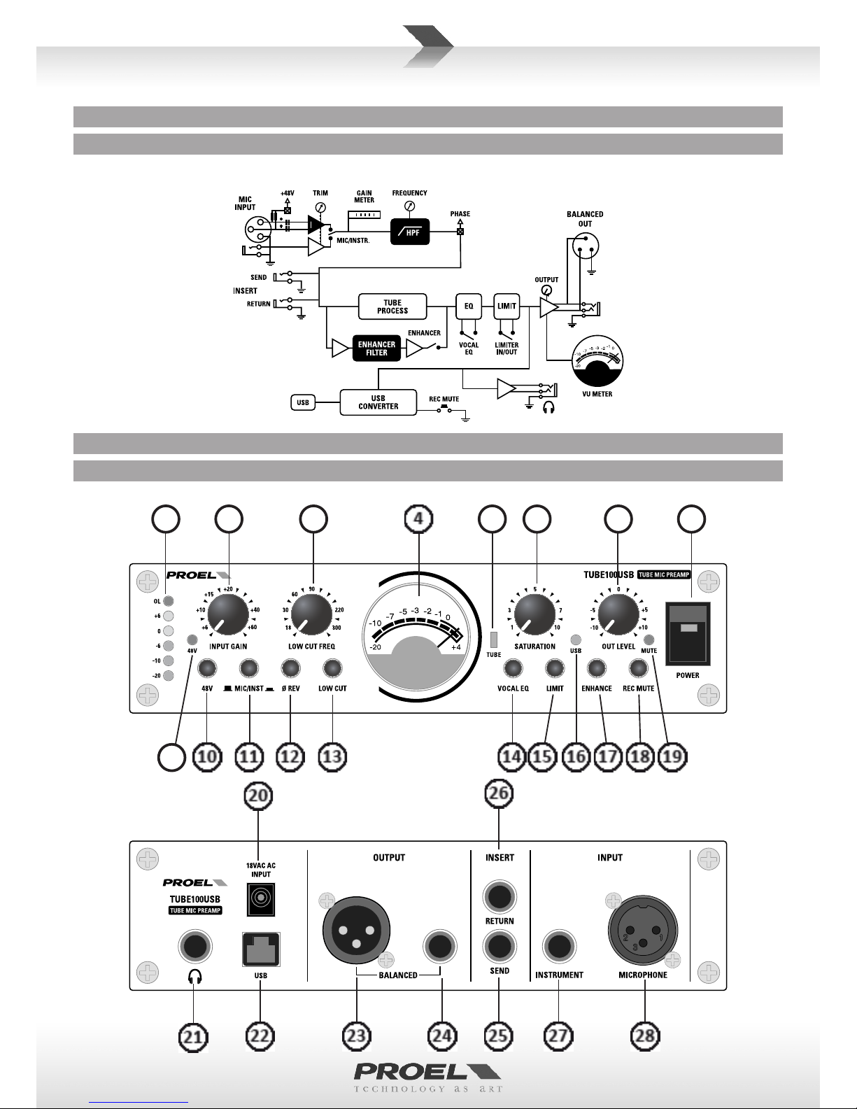
BLOCK DIAGRAM (FIG.1) . . . . . . . . . . . . . . . . . . . . . . . . 6
CONTROLPANEL(FIG.2)......................... 6
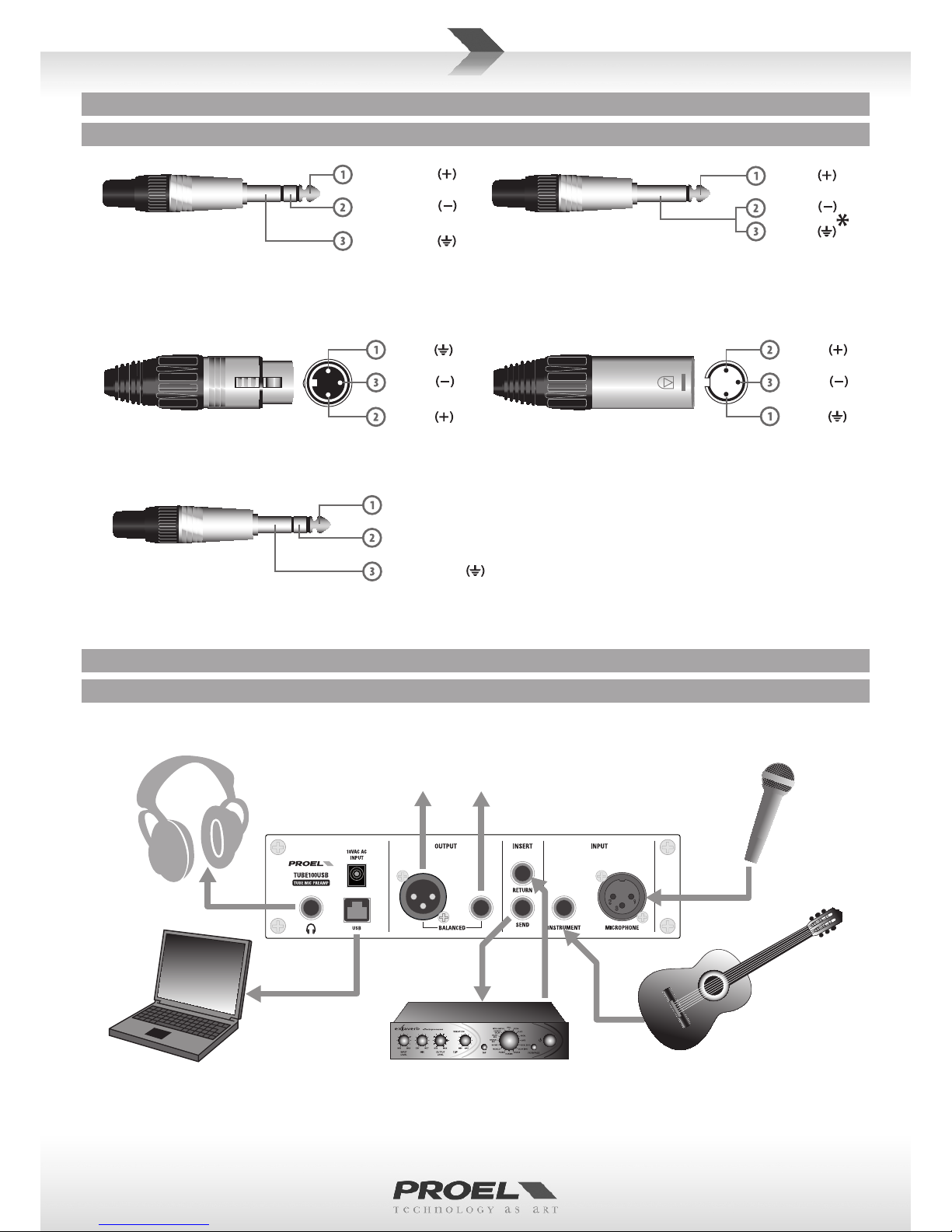
CONNECTIONS(FIG.3) .......................... 7
CONFIGURATION EXAMPLE (FIG.4) . . . . . . . . . . . . . . . . 7
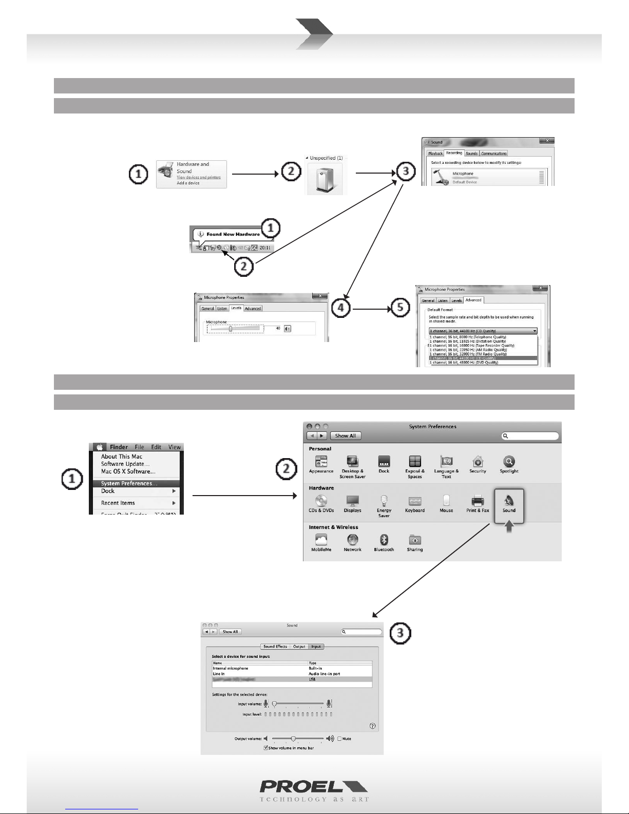
WINDOWSSETUP(FIG.5)........................ 8
MACSETUP(FIG.6)............................. 8
SAFETY AND PRECAUTIONS . . . . . . . . . . . . . . . . . . . . . . 9
CECONFORMITY............................... 9
PACKAGING, SHIPPING AND COMPLAINT . . . . . . . . . . . 9
WARRANTY AND PRODUCTS RETURN . . . . . . . . . . . . . 10
INSTALLATION AND DISCLAIMER . . . . . . . . . . . . . . . . . 10
POWER SUPPLY AND MAINTENANCE . . . . . . . . . . . . . 10
FCC COMPLIANCE NOTICE . . . . . . . . . . . . . . . . . . . . . . 10
GENERALINFORMATION....................... 11
OPERATING INSTRUCTIONS (FIG. 1-4) . . . . . . . . . . . . . 11
USBSETUP(FIG.5-6) .......................... 13
INDICE
SPECIFICHETECNICHE .......................... 3
DIAGRAMMA A BLOCCHI (FIG.1) . . . . . . . . . . . . . . . . . . 6
PANNELLO DI CONTROLLO (FIG.2) . . . . . . . . . . . . . . . . . 6
CONNESSIONI(FIG.3)........................... 7
ESEMPIO DI CONFIGURAZIONE (FIG.4) . . . . . . . . . . . . . 7
CONFIGURAZIONE WINDOWS (FIG.5) . . . . . . . . . . . . . . 8
MACWINDOWS(FIG.6)......................... 8
AVVERTENZE PER LA SICUREZZA . . . . . . . . . . . . . . . . . 14
INCASODIGUASTO........................... 14
CONFORMITÀCE.............................. 14
IMBALLAGGIO, TRASPORTO E RECLAMI . . . . . . . . . . . 14
GARANZIEERESI ............................. 15
INSTALLAZIONE E LIMITAZIONI D’USO. . . . . . . . . . . . . 15
ALIMENTAZIONE E MANUTENZIONE . . . . . . . . . . . . . . 15
INFORMAZIONI GENERALI . . . . . . . . . . . . . . . . . . . . . . 16
ISTRUZIONI OPERATIVE (FIG. 1-4) . . . . . . . . . . . . . . . . 16
IMPOSTAZIONI USB (FIG. 5-6) . . . . . . . . . . . . . . . . . . . 18
5............................................................
6....................................................
6......................................................
7.......................................................
7..........................................
8..........................................
8........................................
34...............................................
34.............................................................
35.................................................................CE
35.........................................
35............................................................
35...........................................
35............................................................
36..............................................................
36............................................
38...............................................USB
ÍNDICE
CARACTERÍSTICAS TÉCNICAS . . . . . . . . . . . . . . . . . 5
DIAGRAMA DE BLOQUES (FIG.1) . . . . . . . . . . . . . . 6
PANEL DE CONTROL (FIG.2) . . . . . . . . . . . . . . . . . . 6
CONEXIONES(FIG.3)........................7
EJEMPLO DE CONFIGURACIÓN (FIG.4) . . . . . . . . . 7
CONFIGURACIÓN WINDOWS (FIG.5) . . . . . . . . . . . 8
CONFIGURACIÓN MAC (FIG.6) . . . . . . . . . . . . . . . . 8
ADVERTENCIAS PARA LA SEGURIDAD . . . . . . . . . 29
ENCASODEAVERÍA.......................29
CONFORMIDADCE........................29
EMBALAJE, TRANSPORTE Y RECLAMACIONES. . . 30
GARANTÍAS Y DEVOLUCIONES . . . . . . . . . . . . . . . 30
INSTALACIÓN Y LIMITACIONES DE USO . . . . . . . . 30
ALIMENTACIÓN Y MANTENIMIENTO . . . . . . . . . . 30
INFORMACIÓN GENERAL . . . . . . . . . . . . . . . . . . . 31
INSTRUCCIONES OPERATIVAS (FIG. 1-4) . . . . . . . 31
CONFIGURACIONES USB (FIG. 5-6) . . . . . . . . . . . 33
INHALT
TECHNISCHEDATEN..............................4
BLOCKDIAGRAMM (ABB.1) . . . . . . . . . . . . . . . . . . . . . . . . 6
REGLER (ABB.2). . . . . . . . . . . . . . . . . . . . . . . . . . . . . . . . . . 6
ANSCHLÜSSE(ABB.3).............................7
KONFIGURATIONSBEISPIEL (ABB.4) . . . . . . . . . . . . . . . . . . 7
WINDOWSKONFIGURATION (ABB. 5) . . . . . . . . . . . . . . . . 8
MAC-KONFIGURATION (ABB. 6) . . . . . . . . . . . . . . . . . . . . . 8
SICHERHEITSHINWEISE...........................19
BEIEINEMDEFEKT..............................19
EG-KONFORMITÄT...............................19
VERPACKUNG, TRANSPORT UND REKLAMATIONEN . . . . 19
GARANTIE UND RÜCKGABE . . . . . . . . . . . . . . . . . . . . . . . 20
INSTALLATION UND VERWENDUNGSEINSCHRÄNKUNGEN. 20
STROMVERSORGUNG UND INSTANDHALTUNG . . . . . . . 20
ALLGEMEINE INFORMATIONEN . . . . . . . . . . . . . . . . . . . .21
GEBRAUCHSANLEITUNG (ABB. 1-4). . . . . . . . . . . . . . . . .21
USB-EINSTELLUNGEN (ABB. 5-6) . . . . . . . . . . . . . . . . . . . 23
INDEX
SPÉCIFICATIONS TECHNIQUES . . . . . . . . . . . . . . . . . . . . 4
DIAGRAMME À BLOCS (FIG.1) . . . . . . . . . . . . . . . . . . . . 6
PANNEAU DE COMMANDE (FIG.2). . . . . . . . . . . . . . . . . 6
CONNEXIONS(FIG.3) ........................... 7
EXEMPLE DE CONFIGURATION (FIG.4). . . . . . . . . . . . . . 7
CONFIGURATION WINDOWS (FIG.5) . . . . . . . . . . . . . . . 8
CONFIGURATION MAC (FIG.6) . . . . . . . . . . . . . . . . . . . . 8
MISES EN GARDE DE SÉCURITÉ . . . . . . . . . . . . . . . . . . 24
ENCASDEPANNE............................. 24
CONFORMITÉCE.............................. 24
EMBALLAGE, TRANSPORT ET RÉCLAMATIONS . . . . . . 25
GARANTIESETRETOURS ....................... 25
INSTALLATION ET LIMITES D'UTILISATION . . . . . . . . . . 25
ALIMENTATION ET MAINTENANCE . . . . . . . . . . . . . . . 25
INFORMATIONS GÉNÉRALES . . . . . . . . . . . . . . . . . . . . 26
INSTRUCTIONS DE FONCTIONNEMENT (FIG. 1-4). . . . 26
CONFIGURATIONS USB (FIG. 5-6). . . . . . . . . . . . . . . . . 28

TECHNICAL SPECIFICATIONS SPECIFICHE TECNICHE
Model TUBE100USB
System Type Tube Mic Preamp with USB
Microphone Input Secon
Impedance 2.5 Kohm
Sensivity from 0 to -60 dBu
Connectors XLR-F (balanced)
Instrument Input Secon
Impedance >1 Mohm
Sensivity from +10 to -50 dBu
Connector 1/4" jack (unbalanced)
Insert Secon
Impedance send 100 ohm
Impedance return 10 Kohm
Nominal out Level 0 dBu
Connectors 1/4" jack (unbalanced)
Output Secon
Impedance 60 ohm
Nominal out level +4 dBu
Maximum out level +21 dBu
Connectors XLR-M and 1/4" jack (balanced)
USB Output Secon
Type USB 1.1 and 2.0 (type B)
Converter 16 bit
Sampling rate 48 KHz
System performance
Distoron THD < 0.008% (at 1 KHz +4 dBu)
Noise < -95 dB unweighted
Frequency response 20 Hz - 20 kHz (-0.5 dB)
General
Supply 18 VAC 1000 mA (adapter included)
Mains Supply Voltage 100-120 VAC or 220-240 VAC, 50-60 Hz
Consumpon 32 W
Dimensions (W x H x D) 200 x 56 x 140 mm
Weight 1,8 Kg
Modello TUBE100USB
Tipo di Sistema Preamp Microfonico Valvolare con USB
Sezione Ingresso Microfono
Impedenza 2.5 Kohm
Sensibilità da 0 a -60 dBu
Conneori XLR-F (bilanciato)
Sezione Ingresso Strumento
Impedenza >1 Mohm
Sensibilità da +10 a -50 dBu
Conneori 6,3 mm jack (sbilanciato)
Sezione Insert
Impedenza send 100 ohm
Impedenza return 10 Kohm
Livello nominale uscita 0 dBu
Conneori 6,3 mm jack (sbilanciato)
Sezione Uscita
Impedenza 60 ohm
Livello nominale uscita +4 dBu
Livello massimo uscita +21 dBu
Conneori XLR-M e 1/4" jack (bilancia)
Sezione Uscita USB
Tipo USB 1.1 e 2.0 (type B)
Conversione 16 bit
Frequenza campionamento 48 KHz
System performance
Distorsione THD < 0.008% (a 1 KHz +4 dBu)
Noise < -95 dB non pesato
Frequency response 20 Hz - 20 kHz (-0.5 dB)
Generali
Alimentazione 18 VAC 1000 mA (adaatore incluso)
Tensione di rete 100-120 VAC o 220-240 VAC, 50-60 Hz
Consumo 32 W
Dimensioni (L x A x P) 200 x 56 x 140 mm
Peso 1,8 Kg

TECHNISCHE DATEN SPÉCIFICATIONS TECHNIQUES
Modèle TUBE100USB
Type de Système Preamp Microfonico Valvolare con
USB
Secon Entrée Microphone
Impédance 2.5 Kiloohms
Sensibilité de 0 à -60 dBu
Connecteurs XLR-F (symétrique)
Secon Entrée Instrument
Impédance >1 Mohm
Sensibilité de +10 à -50 dBu
Connecteurs 6,3 mm jack (déséquilibré)
Secon Insert
Impédance send 100 ohms
Impédance return 10 Kiloohms
Niveau nomimal sore 0 dBu
Connecteurs 6,3 mm jack (déséquilibré)
Secon Sore
Impédance 60 ohms
Niveau nomimal sore +4 dBu
Niveau maximal sore +21 dBu
Connecteurs XLR-M et 1/4" jack (équilibrés)
Secon Sore USB
Type USB 1.1 et 2.0 (type B)
Conversion 16 bits
Fréquence échanllonnage 48 KHz
System performance
Distorsion THD < 0.008% (à 1 KHz +4 dBu)
Noise < -95 dB non pesé
Frequency response 20 Hz - 20 kHz (-0.5 dB)
Générales
Alimentaon 18 VAC 1000 mA (adaptateur inclus)
Tension de réseau
100-120 VAC ou 220-240 VAC, 50-60 Hz
Consommaon 32 W
Dimensions (L x H x P) 200 x 56 x 140 mm
Poids 1,8 Kg
Modell TUBE100USB
Systemtyp Mikrofonischer Venlvorverstärker
mit USB
Bereich Mikrofoneingang
Impedanz 2.5 Kohm
Empndlichkeit von 0 bis -60 dBu
Anschlüsse XLR-F (abgeglichen)
Instrument-Eingangsbereich
Impedanz >1 Mohm
Empndlichkeit von +10 bis -50 dBu
Anschlüsse 6,3 mm Klinkenstecker
(unsymmetrisch)
Einsteckbereich
Sende-Impedanz 100 Ohm
Rück-Impedanz 10 kOhm
Nennpegel Ausgang 0 dBu
Anschlüsse 6,3 mm Klinkenstecker
(unsymmetrisch)
Ausgangsbereich
Impedanz 60 Ohm
Nennpegel Ausgang +4 dBu
Höchstpegel Ausgänge +21 dBu
Anschlüsse XLR-M und 1/4" Klinkenstecker
(symmetrisch)
Bereich USB-Ausgänge
Typ USB 1.1 und 2.0 (Typ B)
Umkehrung 16 bit
Abtasthäugkeit 48 KHz
Systemleistung
THD Verzerrung < 0.008% (bei 1 KHz +4 dBu)
Rauschen < -95 dB nicht abgewogen
Frequency response 20 Hz - 20 kHz (-0.5 dB)
Allgemeine
Stromversorgung 18 VAC 1000 mA (einschl. Adapter)
Netzspannung
100-120 VAC oder 220-240 VAC, 50-60 Hz
Verbrauch 32 W
Abmessungen (B x H x T) 200 x 56 x 140 mm
Gewicht 1,8 Kg

CARACTERÍSTICAS TÉCNICAS
Modelo TUBE100USB
Tipo de sistema Preamplicador de Micrófono de
Válvulas con USB
Sección Entrada Micrófono
Impedancia 2.5 Kohm
Sensibilidad de 0 a -60 dBu
Conectores XLR-F (balanceado)
Sección Entrada Instrumento
Impedancia >1 Mohm
Sensibilidad de +10 a -50 dBu
Conectores 6,3 mm jack (desbalanceado)
Sección Insert
Impedancia send 100 ohm
Impedancia return 10 Kohm
Nivel nominal salida 0 dBu
Conectores 6,3 mm jack (desbalanceado)
Sección Salida
Impedancia 60 ohm
Nivel nominal salida +4 dBu
Nivel máximo salida +21 dBu
Conectores XLR-M y 1/4" jack (balanceados)
Sección Salida USB
Tipo USB 1.1 y 2.0 (type B)
Conversión 16 bit
Frecuencia muestreo 48 KHz
System performance
Distorsión THD < 0.008% (a 1 KHz +4 dBu)
Noise < -95 dB no pesado
Frequency response 20 Hz - 20 kHz (-0.5 dB)
Generales
Alimentación 18 VCA 1000 mA (adaptador incluido)
Tensión eléctrica 100-120 VCA o 220-240 VCA, 50-60 Hz
Consumo 32 W
Dimensiones (L x A x P) 200 x 56 x 140 mm
Peso 1,8 Kg
TUBE100USB
USB
2.5
-600
XLR-F
1>
-50+10
6.3
100
10
0
6.3
60
+4
+21
1/4XLR-M
USB
)B2.0USB 1.1
16
48
THD+410.008% <
Noise-95 <
-0.52020
100018
220-240100-120
50-60
32
14056200
1,8

6
VU METER
VU METER
VU METER
9
3215678
BLOCK DIAGRAM (FIG.1) BLOCKDIAGRAMM (ABB.1)
DIAGRAMMA A BLOCCHI (FIG.1)
DIAGRAMME À BLOCS (FIG.1)
)1
DIAGRAMA DE BLOQUES (FIG.1)
CONTROL PANEL (FIG.2) REGLER (ABB.2)
PANNELLO DI CONTROLLO (FIG.2)
PANNEAU DE COMMANDE (FIG.2)
)2
PANEL DE CONTROL (FIG.2)

7
OUTPUT
Jack (balanced)
USCITA
Jack (bilanciato)
CUFFIA
Jack stereo
HEADPHONES
Stereo Jack
USCITA
XLR bilanciato femmina
OUTPUT
Balanced female XLR
ground
hot
cold
sleeve - ground
p - hot
ring - cold
MICROFONO
XLR bilanciato maschio
MICROPHONE
Balanced male XLR
ground
hot
cold
p - le
ring - right
sleeve - ground
Jack (sbilanciato)
INSTRUMENT, SEND, RETURN STRUMENTO, SEND, RETURN
Jack (unbalanced)
ground
p - hot
cold
*nota: conneere insieme cold e ground
per cavi da bilanciato a sbilanciato
*note: connect both cold and ground
to make cable from balanced to unbalanced
to audio system or
other recording equipment
headphones
personal computer
effect processor
instrument with
audio output
microphone
CONNECTIONS (FIG.3)
CONFIGURATION EXAMPLE (FIG.4)
ANSCHLÜSSE (ABB.3)
KONFIGURATIONSBEISPIEL (ABB.4)
CONNESSIONI (FIG.3)
ESEMPIO DI CONFIGURAZIONE (FIG.4)
CONNEXIONS (FIG.3)
EXEMPLE DE CONFIGURATION (FIG.4)
)3
)4
CONEXIONES (FIG.3)
EJEMPLO DE CONFIGURACIÓN (FIG.4)
OUTPUT
Jack (balanced)
USCITA
Jack (bilanciato)
AUSGANG
Klinkenstecker (symmetrisch)
OUTPUT
Balanced female XLR
USCITA
XLR bilanciato femmina
AUSGANG
XLR symmetrisch, weiblich
SORTIE
Jack (symétrique)
SALIDA
Jack (balanceado)
SORTIE
XLR symétrique femelle
SALIDA
XLR balanceado hembra
XLR
HEADPHONES
Stereo jack
CUFFIA
Jack stereo
KOPFHÖRER
Stereo-Klinkenstecker
MICROPHONE
Balanced male XLR
MICROFONO
XLR bilanciato maschio
MIKROFON
XLR symmetrisch, männlich
INSTRUMENT, SEND, RETURN
Jack (unbalanced)
STRUMENTO, SEND, RETURN
Jack (sbilanciato)
INSTRUMENT, SENDEN, RETURN
Klinkenstecker (unsymmetrisch)
CASQUE
Jack stéréo
AURICULARES
Jack estéreo
MICROPHONE
XLR symétrique mâle
MICRÓFONO
XLR balanceado macho
INSTRUMENT, SEND, RETURN
Jack (asymétrique)
INSTRUMENTO, SEND, RETURN
Jack (desbalanceado)
*note: connect both cold and ground to make cable from balanced to unbalance
*nota: conneere insieme cold e ground per cavi da bilanciato a sbilanciato
*Hinweis: Bei Kabeln von symmetrisch zu unsymmetrisch Cold und Masse
zusammen anschließen
*
note : brancher ensemble cold et ground pour câbles de symétrique à asymétrique
*nota: conecte juntos cold y ground para cables de balanceado a desbalanceado

8
from control panel:
da pannello di controllo:
vom Bedienfeld:
du tableau de contrôle :
desde el panel de control:
from desktop:
dalla scrivania:
vom Schreibsch:
du bureau :
desde el escritorio:
WINDOWS SETUP (FIG.5)
MAC SETUP (FIG.6)
WINDOWSKONFIGURATION (ABB. 5)
MAC-KONFIGURATION (ABB. 6)
CONFIGURAZIONE WINDOWS (FIG.5)
MAC WINDOWS (FIG.6)
CONFIGURATION WINDOWS (FIG.5)
CONFIGURATION MAC (FIG.6)
)5
)6
CONFIGURACIÓN WINDOWS (FIG.5)
CONFIGURACIÓN MAC (FIG.6)

9
This marking shown on the product or its literature, indicates that it should not be disposed with other household wastes at the end of its
working life. To prevent possible harm to the environment or human health from uncontrolled waste disposal, please separate this from
other types of wastes and recycle it responsibly to promote the sustainable reuse of material resources. Household users should contact
either the retailer where they purchased this product, or their local government oce, for details of where and how they can take this
item for environmentally safe recycling. Business users should contact their supplier and check the terms and condions of the purchase
contract. This product should not be mixed with other commercial wastes for disposal.
The lightning ash with arrowhead symbol within an equilateral triangle is intended to alert the user to the presence of uninsulated
“dangerous voltage” within the product’s enclosure, that may be of sucient magnitude to constute a risk of electric shock to persons.
The exclamaon point within an equilateral triangle is intended to alert the user to the presence of important operang and maintenance
(servicing) instrucons in the literature accompanying the appliance.
The informaon contained in this publicaon has been carefully prepared and checked. However no responsibility will be taken for any errors. All
rights are reserved and this document cannot be copied, photocopied or reproduced in part or completely without wrien consent being obtained
in advance from PROEL. PROEL reserves the right to make any aesthec, funconal or design modicaon to any of its products without any prior
noce. PROEL assumes no responsibility for the use or applicaon of the products or circuits described herein.
SAFETY AND PRECAUTIONS
• CAUTION: before using this product read carefully the following safety instrucons. Take a look of this manual enrely and preserve it for
future reference.
When using any electric product, basic precauons should always be taken, including the following:
– To reduce the risk, close supervision is necessary when the product is used near children.
– Protect the apparatus from atmospheric agents and keep it away from water, rain and high humidity places.
– This product should be site away from heat sources such as radiators, lamps and any other device that generate heat.
– This product should be located so that its locaon or posion does not interfere with its proper venlaon and heang dissipaon.
– Care should be taken so that objects and liquids do not go inside the product.
– The product should be connected to a power supply mains line only of the type described on the operang instrucons or as marked on the
product. Connect the apparatus to a power supply using only power cord included making always sure it is in good condions.
– WARNING: The mains plug is used as disconnect device, the disconnect device shall remain readily operable.
– Do not cancel the safety feature assured by means of a polarized line plug (one blade wider than the other) or with a earth connecon.
– Make sure that power supply mains line has a proper earth connecon.
– Power supply cord should be unplugged from the outlet during strong thunderstorm or when le unused for a long period of me.
– Do not place objects on the product’s power cord or place it in a posion where anyone could trip over, walk on or roll anything over it. Do not
allow the product to rest on or to be installed over power cords of any type. Improper installaons of this type create the possibility of re hazard
and/or personal injury.
– This product may be capable of producing sound levels that could cause
permanent hearing loss. Exposure to extremely high noise levels may cause
permanent hearing loss. Individuals vary considerably in suscepbility to noise-
induced hearing loss, but nearly everyone will lose some hearing if exposed
to sufficiently intense noise for a period of time. The U.S. Government’s
Occupational Safety and Health Administration (OSHA) has specified the
permissible noise level exposures shown in the following chart. According to
OSHA, any exposure in excess of these permissible limits could result in some
hearing loss. To ensure against potenally dangerous exposure to high sound
pressure levels, it is recommended that all persons exposed to equipment
capable of producing high sound pressure levels use hearing protectors while
the equipment is in operaon. Ear plugs or protectors in the ear canals or over
the ears must be worn when operang the equipment in order to prevent
permanent hearing loss if exposure is in excess of the limits set forth here. Keep
your's aenon that children and pets are more suscepble to excessive noise
levels.
IN CASE OF FAULT
• In case of fault or maintenance this product should be inspected only by qualied service personnel when:
– There is a aw either in the connecons or in the supplied connecng cables.
– Liquids have spilled inside the product.
– The product has fallen and been damaged.
– The product does not appear to operate normally or exhibits a marked change in performance.
– The product has been lost liquids or gases or the enclosure is damaged.
• Do not operate on the product, it has no user-serviceable parts inside, refer servicing to an authorized maintenance centre.
CE CONFORMITY
• Proel products comply with direcve 2004/108/EC (EMC), as stated in EN 55103-1 and EN 55103-2 standards and with direcve 2006/95/CE
(LVD), as stated in EN 60065 standard.
• Under the EM disturbance, the rao of signal-noise will be changed above 10dB.
PACKAGING, SHIPPING AND COMPLAINT
• This unit package has been submied to ISTA 1A integrity tests. We suggest you control the unit condions immediately aer unpacking it.
• If any damage is found, immediately advise the dealer. Keep all unit packaging parts to allow inspecon.
• Proel is not responsible for any damage that occurs during shipment.
Duraon Per Day
In Hours
Sound Level dBA
Slow Response
Typical
Example
8 90 Duo in small club
6 92
4 95 Subway Train
3 97
2 100 Very loud classical music
1.5 102
1 105 Trac noise
0.5 110
0.25 or less 115 Loudest parts at a rock concert

10
• Products are sold “delivered ex warehouse” and shipment is at charge and risk of the buyer.
• Possible damages to unit should be immediately noed to forwarder. Each complaint for package tampered with should be done within eight
days from product receipt.
WARRANTY AND PRODUCTS RETURN
• Proel products have operang warranty and comply their specicaons, as stated by manufacturer.
• Proel warrants all materials, workmanship and proper operaon of this product for a period of two years from the original date of purchase. If
any defects are found in the materials or workmanship or if the product fails to funcon properly during the applicable warranty period, the owner
should inform about these defects the dealer or the distributor, providing receipt or invoice of date of purchase and defect detailed descripon.
This warranty does not extend to damage resulng from improper installaon, misuse, neglect or abuse. Proel S.p.A. will verify damage on returned
units, and when the unit has been properly used and warranty is sll valid, then the unit will be replaced or repaired. Proel S.p.A. is not responsible
for any "direct damage" or "indirect damage" caused by product defecveness.
INSTALLATION AND DISCLAIMER
• Proel products have been expressly designed for audio applicaon, with signals in audio range (20Hz to 20kHz). Proel has no liability for damages
caused in case of lack of maintenance, modicaons, improper use or improper installaon non-applying safety instrucons and at the state of
the art.
• Proel S.p.A. reserves the right to change these specicaons at any me without noce.
POWER SUPPLY AND MAINTENANCE
• Clean only with dry cloth.
• Check periodically that the slots for its proper venlaon and heang dissipaon are not obstructed by dust, remove the dust using a dry brush
or a compressed air gun.
• The apparatus of Proel have been designed with CLASS I construcon and must be connected always to a mains socket outlet with a protecve
earth connecon (the third grounding prong).
• Before connecng the product to the mains outlet make certain that the mains line voltage matches that shown on the rear of the product, a
tolerance of up to ±10% is acceptable.
• THE REPLACEMENT OF FUSES INSIDE THE APPARATUS MUST BE MADE ONLY BY QUALIFIED PERSONNEL.
• CHECK THE CONDITION OF THE PROTECTION FUSE, ACCESSIBLE OUTWARD, ONLY WITH THE APPARATUS SWITCHED OFF AND DISCONNECTED
FROM THE MAINS LINE OUTLET.
• REPLACE THE PROTECTION FUSE ONLY WITH SAME TYPE AS SHOWN ON THE PRODUCT.
• IF AFTER THE SUBSTITUTION, THE FUSE INTERRUPTS AGAIN THE APPARATUS WORKING, DO NOT TRY AGAIN THEN CONTACT THE PROEL
SERVICE CENTRE.
FCC COMPLIANCE NOTICE
This device complies with part 15 of the FCC rules. Operaon is subject to the following two condions:
(1) This device may not cause harmful interference, and
(2) this device must accept any interference received, including interference that may cause undesired operaon.
CAUTION: Changes or modicaons not expressly approved by the party responsible for compliance could void
the user’s authority to operate the equipment.
NOTE: This equipment has been tested and found to comply with the limits for a Class B digital device, pursuant to
part 15 of the FCC Rules. These limits are designed to provide reasonable protecon against harmful interference in
a residenal installaon. This equipment generates, uses, and can radiate radio frequency energy and, if not installed
and used in accordance with the instrucon manual, may cause harmful interference to radio communicaons.
However, there is no guarantee that interference will not occur in a parcular installaon. If this equipment does
cause harmful interference to radio or television recepon, which can be determined by turning the equipment o
and on, the user is encouraged to try to correct the interference by one or more of the following measures:
• Reorient or relocate the receiving antenna.
• Increase the separaon between the equipment and receiver.
• Connect the equipment into an outlet on a circuit dierent from that to which the receiver is connected.
• Consult the dealer or an experienced radio/TV technician for help.

11
GENERAL INFORMATION
Thank you for having chosen a PROEL product.
The TUBE100USB is a rst-class tool for professional microphone and instrument amplicaon that combines low noise
transistor technology, the warmth and hot sound of a vintage 12AX7 dual triode valve circuit, the straight-forward A/D
USB audio acquision in almost any personal computer. The clear and simple user interface oers easy access to all
features:
• 12AX7 tube preamp secon for adding warmth to microphones and instruments.
• Built-in low-noise +48V phantom power.
• PHASE reverse switch, adjustable LO-CUT lter, VOCAL EQ, built-in LIMITER circuit
• Input and output GAIN controls plus SATURATION funcon.
• Accurate dual LEVEL METER
• Microphone (XLR-F) and instrument (¼” JACK) inputs.
• XLR-M and ¼” JACK balanced outputs.
• USB 1.1 compliant, compable with Windows XP/Vista/7/8 and Mac OS 9.1 and newer.
OPERATING INSTRUCTIONS (FIG. 1-4)
1. INPUT VU METER
To monitor the signal being presented to the preamp’s input, there is a six segment LED VU meter indicang –20, -10,
-6, 0, +6 dB and OL (overload). Use the INPUT VU METER when you are seng your inial input level with the INPUT
GAIN control.
2. INPUT GAIN control
The INPUT GAIN is used to set the level of the input signal. The control knob provides a range of gain from 0 to +60 dB
using the MICROPHONE input or from -10 to +50 dB using the INSTRUMENT input. Be sure to monitor the INPUT VU
METER and try to set the INPUT GAIN control so that the meter reads about 0 dB. If you see the OL LED light you are
“overloading” and the sound may become distorted. If this happens, simply back down on the INPUT GAIN control unl
the OL light exnguishes.
3. LOW CUT FREQ control
This controller sets the exact frequency to start aenuang the low-end. Be sure that the LOW CUT switch is engaged.
The controller allows you to set the low-cut aenuaon to any frequency between 18 and 300 Hz.
4. OUTPUT VU METER
This VU meter monitors the signal being sent from the TUBE100USB with a scale from innity to +4 dB. Use the OUTPUT
VU METER when you are seng your output level using the OUTPUT LEVEL control. Try to set the level so that the meter
reads about -3 dB to 0 dB. If you see the pointer stay in the red area (more than 0 dB) of the OUTPUT VU METER, you are
“overloading” and the sound may become distorted. If this happens, simply back down on the OUTPUT LEVEL control
unl the meter reads about 0 dB or less.
5. TUBE indicator
Indicator LED that lights when the 12AX7 internal valve is ready for operaon (pre-heang of the valve lament).
6. SATURATION control
Used to adjust the total amount of even harmonic overtones and “warmth” sound generated by the tube circuit.
7. OUT LEVEL control
Used to control the output level. When the knob is fully counter-clockwise the output is o , at "0" marking indicates a
+4dBu nominal output level, with a gain of 10dB when fully rotate clockwise. It is used in combinaon with the OUTPUT
VU METER to set the right level while recording.
8. POWER switch
This switch turns on and o the TUBE100USB, the build-in LED lights when pressed to the “on” posion.
9. 48V indicator
RED LED that indicates when the 48 V phantom power is acvated.
10. 48V switch
Switch used to acvate the 48 V phantom power. Most professional condenser microphones require phantom power,
which is a lower DC voltage delivered to the microphone on pin 2 and 3 of the XLR microphone connector. Dynamic
microphones do not require phantom power, however phantom power will not harm most dynamic microphones should
you plug one in while the phantom power is on. Check the manual of your microphone to nd out for sure whether or
not phantom power can damage it.

12
11. MIC/INST switch
The MIC/INST switch is used to select the input of the TUBE100USB. When using a microphone, connect the microphone
to the MICROPHONE INPUT (XLR) and set the switch to the “MIC” posion (switch is in the UP posion). When using an
instrument (guitar, bass, etc.) or a line level device (keyboard, turn tables, drum machine, etc.), connect the instrument
/ device to the INSTRUMENT INPUT (JACK) and press the MIC/INST switch (switch is in the DOWN posion).
12. Ø REV phase switch
For a variety of miking and mixing techniques, it may be necessary to invert the signal phase from the source you have
plugged into your TUBE100USB preamp. When the PHASE switch is pressed in, the input signal is inverted.
13. LOW CUT switch
This switch cuts low frequencies below the frequency set with the LOW CUT FREQ control at a rate of 12 dB per octave.
The LOW CUT lter can help reducing the possibility of feedback in live situaons and to reducing stage rumble, mic
handling clunks, and breath pops.
14. VOCAL EQ switch
Switch used to acvate the Vocal EQ circuit providing an equalizer preset to “enlighten” and “clear” the voice. This preset
lis the mid-high frequencies by 3 dB at 5 kHz with 1 octave range.
15. LIMIT switch
Press the LIMIT switch to engage the limiter processor. A limiter is a processor that automacally allows signals below
an acceptable input level to pass unaected while aenuang the peaks of stronger signals that exceed this acceptable
input level. Thus, using a limiter will help you to avoid unwanted peaks or overloads in the signal, which can someme
cause undesired distoron. The threshold of the limiter is xed at the nominal internal level of +4dBu.
16. USB indicator
Blue LED indicator that indicates when the preamp is properly connected to a PC.
17. ENHANCE switch
Due to the limiter acon some high frequency contents should be lost. The ENHANCE funcon works by adding high
frequencies back to signal only when the limiter works. The result is a restoraon of high frequencies even if the limiter
processor is acve. Press the ENHANCE switch to engage this funcon.
18. REC MUTE switch
The mute switch allows you to mute the output signal of the TUBE100USB on both the analog (XLR / jack) and digital
(USB) outputs. This funcon can be helpful in some occasions, e. g. listening to playbacks.
19. MUTE indicator
The MUTE LED indicates whether the mute funcon is acvated.
20. 18V~ socket
Here’s where you plug in the TUBE100USB’s external power supply. You should always connect your power supply to
the TUBE100USB before you plug the power supply into an electrical outlet.
21. HEADPHONES jack
6.3 mm (1/4-inch) STEREO JACK connector for headphones output: only stereo headphones with a minimum impedance
of 32 Ohms should be connected to this output.The stereo jack connectors are wired as follow:
Tip = posive LEFT channel signal
Ring = posive RIGHT channel signal
Sleeve = common negave shield or ground for both channels
22. USB PORT socket
It routes the output signal through the USB port in crystal-clean, 16-bit, 48 kHz stereo digital audio for high quality
recording with Windows and Macintosh computers. See above on this manual for more details.
23. OUTPUT xlr (balanced)
The XLR connector provides a balanced line-level signal. Connect it to the inputs of an audio recorder, processors
(equalizers, mul-band compressors and so on) or other audio system. The XLR output is wired as follows:
Pin 1 = shield or ground
Pin 2 = + posive or “hot”
Pin 3 = - negave or “cold”
24. OUTPUT jack (balanced)
The jack connector provides a balanced line-level signal. This output is hard wired with the previous XLR output.
The JACK output is wired as follows:

13
Tip = + posive or "hot"
Ring = - negave or "cold"
Sleeve = shield or ground
When connecng an unbalanced signal, wire them as follows:
Pin2 / Tip = + posive or "hot"
Pin 1-3 / Sleeve = shield or ground
25. INSERT SEND jack output
In combinaon with INSERT RETURN is where you connect serial eects such as compressors, equalizers, de-essers or
lters. The jack connector is unbalanced and must be connected to the input of the external processor.
26. INSERT RETURN jack input
In combinaon with INSERT SEND is where you connect serial eects such as compressors, equalizers, de-essers or lters.
The jack connector is unbalanced and must be connected to the output of the external processor.
27. INSTRUMENT Input
This is a ¼” (6.3mm) jack connector with hi-Z input impedance, which accepts a direct instrument signal or a unbalanced
line level input signal from almost any source. It is wired as follows:
Tip = + posive or “hot”
Sleeve = shield or ground
28. MICROPHONE Input
This is a female XLR connector, which accepts a balanced microphone input from almost any type of microphone. The
XLR inputs are wire as follows:
Pin 1 = shield or ground
Pin 2 = + posive or “hot”
Pin 3 = - negave or “cold”
USB SETUP (FIG. 5-6)
Windows operang systems (for Windows XP and Vista/7/8. Other versions may dier):
1. Connect the TUBE100USB with the USB connector of your computer. Windows will recognize the TUBE100USB as USB
microphone and install the required driver automacally (the drivers are always included in the operang system). This
process starts only at the rst connecon of the preamp and usually requires a simple conrmaon one or two mes.
The USB LED will light up when the preamp is properly connected to the computer.
2. Do a right-click on the speaker symbol located in the lower right corner of the desktop. Aerwards, select “Adjust
Audio Properes” (Windows XP) or “Recording Devices” (Windows Vista/7/8). Alternavely, you can access this point
via the control panel -> Sounds and Audio Devices or Hardware and Sound.
3. Windows XP: Change to the “Audio” tab and select the preamp in the eld “Sound recording”. Aerwards, push the
“Volume” buon to adjust the preamp’s volume.
Windows Vista/7/8: Select the preamp from the list. You can adjust the preamp’s volume and recording quality by
pushing the “Congure” buon.
The TUBE100USB preamp is now ready to use. However, you must select the recording device again in most audio
programs. Therefore, start the respective program and open the program’s properties. Afterwards, select the
TUBE100USB preamp as recording device.
Mac OS X:
1. Connect the preamp with the USB connector of your computer. Mac OS X will recognize the TUBE100USB and install
the required driver automacally. The USB LED will light up when the preamp is properly connected to the computer.
2. Open the “System Preferences” from the dock or the main Apple menu. Aerwards, open the Sound preference by
clicking on the “Sound” buon.
3. Change to the “Input” tab and select the preamp. The TUBE100USB is now ready to use.

14
Il marchio riportato sul prodoo o sulla documentazione indica che il prodoo non deve essere smalto con altri riu domesci al
termine del ciclo di vita. Per evitare eventuali danni all’ambiente si invita l’utente a separare questo prodoo da altri pi di riu e di
riciclarlo in maniera responsabile per favorire il riulizzo sostenibile delle risorse materiali. Gli uten domesci sono invita a contaare
il rivenditore presso il quale è stato acquistato il prodoo o l’ucio locale preposto per tue le informazioni relave alla raccolta
dierenziata e al riciclaggio per questo po di prodoo. Gli uten aziendali sono invita a contaare il proprio fornitore e vericare i
termini e le condizioni del contrao di acquisto. Questo prodoo non deve essere smalto unitamente ad altri riu commerciali.
Il simbolo del lampo con freccia in un triangolo equilatero intende avverre l'ulizzatore per la presenza di "tensioni pericolose" non isolate
all'interno dell'involucro del prodoo, che possono avere una intensità suciente a costuire rischio di scossa elerica alle persone.
Il punto esclamavo in un triangolo equilatero intende avverre l'ulizzatore per la presenza di importan istruzioni per l'ulizzo e la
manutenzione nella documentazione che accompagna il prodoo.
Le informazioni contenute in questo documento sono state aentamente redae e controllate. Tuavia non è assunta alcuna responsabilità per
eventuali inesaezze. Tu i diri sono riserva e questo documento non può essere copiato, fotocopiato, riprodoo per intero o in parte senza
previo consenso scrio della PROEL. PROEL si riserva il dirio di apportare senza preavviso cambiamen e modiche esteche, funzionali o di
design a ciascun proprio prodoo. PROEL non assume alcuna responsabilità sull’uso o sul l’applicazione dei prodo o dei circui qui descri.
AVVERTENZE PER LA SICUREZZA
• ATTENZIONE: Durante le fasi di uso o manutenzione, devono essere prese alcune precauzioni onde evitare danneggiamen alle struure
meccaniche ed eleroniche del prodoo.
Prima di ulizzare il prodoo, si prega di leggere aentamente le seguen istruzioni per la sicurezza. Prendere visione del manuale d’uso e
conservarlo per successive consultazioni:
– In presenza di bambini, controllare che il prodoo non rappresen un pericolo.
– Posizionare l’apparecchio al riparo dagli agen atmosferici e a distanza di sicurezza dall’acqua, dalla pioggia e dai luoghi ad alto grado di umidità.
– Collocare o posizionare il prodoo lontano da fon di calore quali radiatori, griglie di riscaldamento e ogni altro disposivo che produca calore.
– Collocare o posizionare il prodoo in modo che non ci siano ostruzioni alla sua propria venlazione e dissipazione di calore.
– Evitare che qualsiasi oggeo o sostanza liquida entri all’interno del prodoo.
– Il prodoo deve essere connesso esclusivamente alla rete elerica delle caraerische descrie nel manuale d’uso o scrie sul prodoo,
usando esclusivamente il cavo rete in dotazione e controllando sempre che sia in buono stato, in parcolare la spina e il punto in cui il cavo esce
dal prodoo.
– ATTENZIONE: Se il cavo rete viene scollegato dall'apparecchio per spegnerlo, il cavo rete rimarrà operavo in quanto la sua spina è ancora
collegata alla rete elerica.
– Non annullare la sicurezza garanta dall'uso di spine polarizzate o con messa a terra.
– Fare aenzione che il punto di alimentazione della rete elerica sia dotato di una eciente presa di terra.
– Disconneere il prodoo dalla rete elerica durante for temporali o se non viene usato per un lungo periodo di tempo.
– Non disporre ogge sul cavo di alimentazione, non disporre i cavi di alimentazione e segnale in modo che qualcuno possa incianparci. Altresì
non disporre l’apparecchio sui cavi di altri appara. Installazioni inappropriate
di questo po possono creare la possibilità di rischio di incendio e/o danni alle
persone.
– Questo prodoo può essere capace di produrre livelli sonori che possono
causare perdite d’udito permanen. Si raccomanda di evitare l’esposizione
ad alti livelli sonori o livelli non confortevoli per lunghi periodi di tempo.
Se si notano perdite d’udito o acufeni (schi) consultare un audiologo. La
sensibilità alla perdita di udito causata da eccessiva esposizione al rumore varia
considerevolmente da individuo a individuo, ma mediamente ciascuno può
accusare perdita di udito se esposto al rumore per un certo periodo di tempo.
Come suggerimento viene riportata la tabella dei tempi massimi di esposizione
giornaliera al rumore al ne di evitare perdite di udito, fonte della tabella è l'ente
per la salute degli Sta Uni (OSHA).
Si fa presente inoltre che sia i bambini che gli animali domesci sono più sensibili
al rumore intenso.
IN CASO DI GUASTO
• In caso di guasto o manutenzione questo prodoo deve essere ispezionato da personale qualicato quando:
– Ci sono dife sulle connessioni o sui cavi di collegamento in dotazione.
– Sostanze liquide sono penetrate all’interno del prodoo.
– Il prodoo è caduto e si è danneggiato.
– Il prodoo non funziona normalmente esibendo una marcato cambio di prestazioni.
– Il prodoo perde sostanze liquide o gassose o ha l’involucro danneggiato.
• Non intervenire sul prodoo. Rivolgersi a un centro di assistenza autorizzato Proel.
CONFORMITÀ CE
• I Prodo Proel sono conformi alla direva 2004/108/EC (EMC), secondo gli standard EN 55103-1 ed EN 55103-2 ed alla direva 2006/95/CE
(LVD), secondo lo standard EN 60065.
• Se sooposto a disturbi EM, il rapporto segnale-rumore può essere superiore a 10dB.
IMBALLAGGIO, TRASPORTO E RECLAMI
• L’imballo è stato sooposto a test di integrità secondo la procedura ISTA 1A. Si raccomanda di controllare il prodoo subito dopo l’apertura
dell’imballo.
• Se vengono riscontra danni informare immediatamente il rivenditore. Conservare quindi l’imballo completo per permeerne l’ispezione.
Ore di esposizione
giornaliera
Livello sonoro in dBA
costante di tempo SLOW
Esempio
Tipico
8 90 Duo acusco in un piccolo club
6 92
4 95 Treno metropolitano
3 97
2 100 Musica classica molto forte
1.5 102
1 105 Rumore da traco urbano intenso
0.5 110
0.25 or less 115 Parte più rumorosa di un concerto rock

15
• Proel declina ogni responsabilità per danni causa dal trasporto.
• Le merci sono vendute “franco nostra sede” e viaggiano sempre a rischio e pericolo del distributore.
• Eventuali avarie e danni dovranno essere contesta al veore. Ogni reclamo per imballi manomessi dovrà essere inoltrato entro 8 giorni dal
ricevimento.
GARANZIE E RESI
• I Prodo Proel sono provvis della garanzia di funzionamento e di conformità alle proprie speciche, come dichiarate dal costruore.
• La garanzia di funzionamento è di 24 mesi dopo la data di acquisto. I dife rileva entro il periodo di garanzia sui prodo vendu, aribuibili a
materiali difeosi o dife di costruzione, devono essere tempesvamente segnala al proprio rivenditore o distributore, allegando evidenza scria
della data di acquisto e descrizione del po di difeo riscontrato. Sono esclusi dalla garanzia dife causa da uso improprio o manomissione. Proel
SpA constata tramite verica sui resi la difeosità dichiarata, correlata all’appropriato ulizzo, e l’eeva validità della garanzia; provvede quindi
alla sostuzione o riparazione dei prodo, declinando tuavia ogni obbligo di risarcimento per danni dire o indire eventualmente derivan
dalla difeosità.
INSTALLAZIONE E LIMITAZIONI D’USO
• I Prodo Proel sono desna esclusivamente ad un ulizzo specico di po sonoro: segnali di ingresso di po audio (20Hz-20kHz). Proel declina
ogni responsabilità per danni a terzi causa da mancata manutenzione, manomissioni, uso improprio o installazione non eseguita secondo le
norme di sicurezza e a regola d'arte.
• La Proel S.p.a. si riserva di modicare il prodoo e le sue speciche senza preavviso.
ALIMENTAZIONE E MANUTENZIONE
• Pulire il prodoo unicamente con un panno asciuo.
• Controllare periodicamente che le aperture di raredamento non siano ostruite da accumuli di polvere, provvedere alla rimozione della polvere
mediante un pennello o aria compressa.
• Gli appara PROEL sono costrui in CLASSE I e prevedono sempre il collegamento mediante presa di corrente con terminale di terra di protezione
(terzo terminale di terra).
• Prima di collegare l'apparecchio alla presa di corrente, accertatevi che la tensione di rete corrisponda a quella indicata sul retro dell’apparato, è
consento un margine del ±10% rispeo al valore nominale.
• LA SOSTITUZIONE DI FUSIBILI ALL'INTERNO DELL'APPARATO È CONSENTITO SOLAMENTE A PERSONALE QUALIFICATO.
• CONTROLLARE LO STATO DEI FUSIBILI DI PROTEZIONE ESCLUSIVAMENTE AD APPARATO SPENTO E DISCONNESSO DALLA RETE ELETTRICA.
• RIMPIAZZARE IL FUSIBILE DI PROTEZIONE ESCLUSIVAMENTE CON UN FUSIBILE CON LE MEDESIME CARATTERISTICHE RIPORTATE SUL
PRODOTTO.
• SE DOPO LA SOSTITUZIONE, IL FUSIBILE INTERROMPE NUOVAMENTE IL FUNZIONAMENTO DELL'APPARATO, NON INSISTERE E CONTATTARE
IL SERVIZIO ASSISTENZA PROEL.

16
INFORMAZIONI GENERALI
Grazie per aver scelto un prodoo PROEL.
TUBE100USB è un preamplicatore di classe elevata per microfoni e strumen professionale che combina stadio di
ingresso a basso rumore, il caldo e piacevole suono del circuito della valvola 12AX7 a doppio triodo, conversione
direa A/D USB per ogni po di computer. La chiara e semplice interfaccia ore un facile accesso a tue queste
caraerische:
• Preamplicatore a valvole con 12AX7 per aggiungere calore al suono di strumen e voci.
• Alimentazione phantom +48V a basso rumore.
• Inversione di fase, passa alto impostabile, equalizzazione per voce, limiter.
• Controllo del guadagno di ingresso, di uscita e della saturazione del suono.
• Doppia visualizzazione del livello.
• Ingresso microfonico XLR-F e per strumento JACK.
• Uscita bilanciata XLR-M e JACK.
• Interfaccia audio USB 1.1 compabile con Windows XP/Vista/7/8 e MAC OS 9.1 o successivo.
ISTRUZIONI OPERATIVE (FIG. 1-4)
1. INPUT VU METER livello di ingresso
Visualizza il segnale del preamplicatore di ingresso, con 6 LED indican -20, -10, -6, 0, +6 dB e OL (overload =
sovraccarico). Usare l' INPUT VU METER per impostare il livello di ingresso iniziale con il controllo di INPUT GAIN.
2. INPUT GAIN controllo guadagno di ingresso
Il controllo di guadagno è usato per impostare il livello del segnale di ingresso. La manopola permee una variazione del
guadagno tra 0 e +60 dB con l'ingresso microfono o tra -10 e +50 dB con l'ingresso jack per strumento. Assicurarsi che,
guardando il VU METER ed impostando il guadagno, si legga un valore aorno a 0 dB. Se si osserva il LED OL accendersi
si sta sovraccaricando l'ingresso e il suono potrebbe essere distorto: se accade occorre ridurre il guadagno anché il
LED OL non si accenda.
3. LOW CUT FREQ controllo frequenza di taglio
Questo controllo imposta la frequenza di taglio delle basse frequenze. Assicurarsi che il tasto LOW CUT sia premuto. La
manopola permee di scegliere una aenuazione dei bassi a da 18 ai 300 Hz.
4. OUTPUT VU METER livello di uscita
Questo VU METER mostra il livello del segnale di uscita tra -innito e +4 dBu. Usare l' OUTPUT VU METER per impostare
il livello di uscita con il controllo di OUTPUT LEVEL. Assicurarsi che, guardando il VU METER ed impostando il livello
di uscita, si legga un valore aorno a 0 dB. Se si osserva l'ago restare a lungo nell'area rossa del VU METER si sta
sovraccaricando l'uscita e il suono potrebbe essere distorto: se accade occorre ridurre il livello di uscita.
5. TUBE indicatore
LED che segnala quando la valvola interna 12AX7 è pronta a lavorare (pre-riscaldamento del lamento della valvola).
6. SATURATION controllo saturazione
Usato per regolare la quantà di armoniche pari ed il calore al suono generato dal circuito valvolare.
7. OUT LEVEL controllo livello uscita
Usato per regolare il livello di uscita. Quando la manopola è al minimo l'uscita è nulla, nella posizione 0 si è al livello
nominale di +4 dBu di uscita, mentre nella posizione massima si ha un guadagno di 10 dB. È usata in combinazione con
il VU METER dell'uscita per impostare il giusto livello di registrazione.
8. POWER interruore di accensione
Commutando questo interruore si accende e spegne il TUBE100USB. Il LED integrato si accende quando acceso.
9. +48V indicatore alimentazione phantom
Questo LED rosso avverte che è avata l'alimentazione phantom nell'ingresso microfonico.
10. +48V interruore alimentazione phantom
Questo interruore ava e disava l'alimentazione phantom nell'ingresso microfonico. La maggior parte dei microfoni
professionali a condensatore richiedono l'alimentazione phantom, la quale è una bassa tensione connua DC portata al
microfono sui terminali 2 e 3 del conneore XLR. I microfoni dinamici non richiedono l'alimentazione phantom, tuavia
l'alimentazione phantom non dovrebbe arrecare alcun danno ai microfoni dinamici se inseri quando accesa. Controllare
il manuale del microfono per assicurarsi se l'alimentazione phantom possa danneggiarlo.
11. MIC/INST seleore ingresso
Il seleore MIC/INST è usato per selezionare l'ingresso del TUBE100USB. Quando si usa un microfono collegarlo
all'ingresso XLR MICROPHONE e impostare il tasto su MIC (sollevato). Quando si usa uno strumento o altro disposivo

17
a livello linea collegarlo all'ingresso JACK INSTRUMENT e impostare il tasto su INST (premuto).
12. Ø REV tasto inversione fase
Data la varietà di combinazioni delle tecniche di microfonaggio e mixaggio, potrebbe essere necessario inverre la fase
della sorgente all'ingresso del TUBE100USB. Quando il tasto PHASE è premuto, il segnale è inverto di fase.
13. LOW CUT tasto ltro bassi
Questo tasto taglia le basse frequenze al di soo della frequenza impostata con il controllo LOW CUT FREQ con pendenza
di 12 dB/oava. L'uso del ltro LO CUT è consigliato dal vivo perché riduce la possibilità di rientri (feedback) e i rumori
da maneggiamento dei microfoni, da vibrazioni del palco e del respiro.
14. VOCAL EQ tasto equalizzazione voce
Avare questo tasto per inserire il circuito di equalizzazione della voce predisposto per schiarirne ed esaltarne il mbro.
Questa equalizzazione aumenta di 3 dB le medio-alte a 5 KHz per un'oava.
15. LIMIT tasto limitatore
Premere il tasto LIMIT per avare il limitatore. Il limitatore è un circuito che automacamente permee al segnale soo
un certo livello di passare inalterato, mentre aenua i picchi di segnale che oltrepassano questo livello. Perciò usando il
limitatore si oerrà un segnale privo di picchi eccessivi che possono saturare e provocare distorsione nelle registrazioni.
La soglia del limiter è ssata al livello nominale interno di +4 dBu.
16. USB indicatore connessione
LED di colore blu che indica quando il preamplicatore TUBE100USB è correamente collegato ad un PC.
17. ENHANCE tasto enfasi al
A causa dell'intervento del limitatore il segnale potrebbe perdere alte frequenze. La funzione ENHANCE aggiunge alte
frequenze al segnale solo quando il limitatore è avo. Il risultato è il riprisno delle alte frequenze quando il limiter
aenua il segnale. Premere il tasto ENHANCE per avare questa funzione.
18. REC MUTE tasto spegnimento segnale
Il tasto MUTE permee di escludere il segnale del TUBE100USB sia dalle uscite analogiche (XLR/JACK) che da quelle
digitali (USB). Questa funzione può essere ule in molte occasioni, in parcolare durante le sessioni di registrazione.
19. MUTE indicatore spegnimento segnale
Il LED MUTE indica che è avo il REC MUTE.
20. 18V~ presa di alimentazione
Presa di ingresso dell'alimentatore esterno AC ADAPTOR del TUBE100USB. Collegare sempre questo conneore prima
di inserire l'alimentatore nella presa di rete.
21. HEADPHONES uscita jack stereo per cua
Questo è il conneore STEREO JACK per l'uscita cua: solo cue stereo con un impedenza minima di 32 Ohm possono
essere connesse a questa uscita. Le uscite stereo sono terminate come segue:
Tip (punta) = posivo segnale canale SINISTRO
Ring (anello) = posivo segnale canale DESTRO
Sleeve (manicoo) = schermo o massa comune per entrambe i canali
22. USB PORT (presa USB)
Tramite questa presa il TUBE100USB invia il segnale audio araverso la porta USB in modalità digitale stereo 16-bit 48
kHz, per registrazioni di alta qualità su computer Windows e Macintosh.
23. OUTPUT (uscita XLR bilanciate)
Ques conneori XLR forniscono un’uscita di livello linea bilanciata (+4 dBu). Collegarla agli ingressi di un registratore
audio, processori (equalizzatori, compressori multi-banda etc.) o altri sistemi audio. L’uscita XLR ha i seguenti
terminali:
Pin 1 = schermo o massa
Pin 2 = + posivo o “caldo”
Pin 3 = - negavo o “freddo”
24. OUTPUT (uscita JACK bilanciate)
Ques conneori JACK forniscono un’uscita di livello linea bilanciata (+4 dBu). Questa uscita è collegata direamente
all'uscita XLR precedente. Le terminazioni dell'uscita JACK sono:
Tip (punta) = + posivo o "caldo"
Ring (anello) = - negavo o "freddo"
Sleeve (manicoo) = schermo o massa

18
E quando si collega un segnale sbilanciato, sono le seguen:
Pin2 / Tip (punta) = + posivo o "caldo"
Pin 1-3 / Sleeve (manicoo) = schermo o massa
25. INSERT SEND uscita jack
In combinazione con INSERT RETURN è dove si connee un eeo esterno in serie al segnale, quale un compressore ,
equalizzatori, de-esser o altro. Il jack è sbilanciato e deve essere collegato all'ingresso del processore esterno.
26. INSERT RETURN ingresso jack
In combinazione con INSERT SEND è dove si connee un eeo esterno in serie al segnale, quale un compressore ,
equalizzatori, de-esser o altro. Il jack è sbilanciato e deve essere collegato all'uscita del processore esterno.
27. INSTRUMENT ingresso jack
Questo è un conneore JACK ¼” (6.3mm) ad alta impedenza (hi-Z), in grado di acceare un segnale audio direamente
da uno strumento o un segnale a livello linea da pracamente qualsiasi apparecchio sbilanciato. Le terminazioni dell'
ingresso JACK sono:
Tip (punta) = + posivo o "caldo"
Sleeve (manicoo) = schermo o massa
28. MICROPHONE ingresso XLR
È un conneore femmina XLR, in grado di acceare un segnale microfonico bilanciato da ogni po di microfono.
Le terminazioni dell’ingresso XLR sono:
Pin 1 = schermo o massa
Pin 2 = + posivo o “caldo”
Pin 3 = - negavo o “freddo”
IMPOSTAZIONI USB (FIG. 5-6)
Sistema operavo Windows (per Windows XP e Vista/7/8 per altre può dierire)
1. Conneere il TUBE100USB al PC tramite la porta USB. Windows riconoscerà il TUBE100USB come Microfono USB e
installerà i driver richies automacamente (i driver sono sempre inclusi nel sistema operavo). Questo processo sarà
eseguito solo alla prima connessione del preamplicatore e picamente richiede una semplice conferma 2 o 3 volte. Il
LED USB si accenderà quando il preamplicatore è correamente connesso al computer.
2. Premere il tasto destro del mouse sul simbolo dell'altoparlante del desktop. Dopodiché scegliere "Regola proprietà
audio" (windows XP) o "Disposivi di registrazione" (windows Vista/7/8). In alternava si può accedere a tali proprietà
anche dal "Pannello di controllo" -> "Suono e periferiche audio" o "Hardware e suoni" seguito da "Gessci disposivi
audio".
3. Windows XP: Scegliere l'echea "Audio" e scegliere il TUBE100USB tra i disposivi di "Registrazione suoni".
Dopodiché clickare su "Volume" per impostarlo.
Windows Vista/7/8: Scegliere il TUBE100USB, quindi regolare il volume e altre proprietà clickando sul boone
"Congura".
Il preamplicatore TUBE100USB è ora pronto all'uso. Tuavia si dovrà selezionare ancora il disposivo di registrazione
nella maggior parte dei programmi di registrazione. Quindi avviare il rispevo programma e aprire le proprietà del
programma. Dopodiché scegliere il TUBE100USB come disposivo di registrazione.
Mac OS X:
1. Conneere il TUBE100USB al Mac tramite la porta USB. Mac OS X riconoscerà il TUBE100USB automacamente e
installerà automacamente i driver. Il LED USB si accenderà quando il preamplicatore è correamente connesso al
computer.
2. Aprire le "Preferenze di sistema" dal dock o dal menu principale della mela. Dopodiché aprire le preferenze suono
clickando sul boone "Sound".
3. Scegliere l'echea "Input" e scegliere il preamplicatore. Il TUBE100USB è ora pronto all'uso.

19
Das Kennzeichen auf dem Gerät oder den beiliegenden Unterlagen zeigt an, dass das Gerät am Ende seiner Lebensdauer nicht im Hausmüll
entsorgt werden darf. Aus Umweltschutzgründen bien wir den Anwender, das Gerät von anderem Müll getrennt zu entsorgen und dem
Recycling zuzuführen, damit die Rohstoe umweltverträglich wiederverwertet werden können. Private Anwender wenden sich dazu
bie an den Händler, bei dem sie das Produkt gekau haben, oder an eine örtliche Behörde, die für Informaonen zur Mülltrennung und
zum Recycling dieser Art von Geräten geben kann. Gewerbliche Anwender werden gebeten, sich an den Zulieferer zu wenden und die
Vertragsbedingungen des Kaufvertrags zu überprüfen. Das Gerät darf nicht zusammen mit anderem Gewerbemüll entsorgt werden.
Das Symbol mit einem Pfeilblitz in einem gleichseigen Dreieck warnt den Anwender vor „gefährlicher Spannung“ ohne Isolierung im Gehäuse
des Geräts. Diese kann hoch genug sein, um Stromschlaggefahr zu verursachen.
Das Ausrufezeichen in einem gleichseigen Dreieck weist den Anwender auf wichge Anweisungen zum Gebrauch und zur Instandhaltung
des Geräts in den beiligenden Unterlagen hin.
Die Angaben in diesem Dokument wurden sorgfälg zusammengestellt und kontrolliert. Für mögliche Ungenauigkeiten übernehmen wir dennoch
keine Haung. Alle Rechte vorbehalten. Das Dokument darf ohne vorherige schriliche Genehmigung von PROEL nicht ganz oder in Teilen kopiert
oder reproduziert werden. PROEL behält sich das Recht vor, ohne Vorankündigung Änderungen an der Gestaltung, an den Funkonen oder
am Design aller ihrer Produkte vorzunehmen. PROEL haet nicht für den Gebrauch oder die Verwendung der hier beschriebenen Geräte oder
elektrischen Systeme.
SICHERHEITSHINWEISE
• ACHTUNG: Während des Gebrauchs und der Instandhaltung müssen einige Vorkehrungen getroen werden, um Beschädigungen der
mechanischen und elektronischen Bestandteile des Geräts zu vermeiden.
Vor dem Gebrauch des Geräts bie die folgenden Sicherheitshinweise aufmerksam durchlesen. Das Handbuch lesen und zum späteren
Nachschlagen auewahren.
– Falls Kinder in der Nähe sind, überprüfen, dass das Gerät keine Gefährdung darstellt.
– Das Gerät so aufstellen, dass es vor Wierungseinüssen, Wasser, Regen und hoher Lufeuchgkeit geschützt ist.
– Das Gerät nicht in der Nähe von Wärmequellen aufstellen, wie Heizkörpern, Heizungsgiern oder anderen Gegenständen, die Wärme abgeben.
– Das Gerät so aufstellen, dass die Belüung und Wärmeableitung nicht behindert wird.
– Darauf achten, dass keine Fremdkörper oder Flüssigkeiten in das Innere des Geräts gelangen.
– Das Gerät darf nur an ein Stromnetz angeschlossen werden, das die im Handbuch oder auf dem Gerät angegebenen Merkmale hat. Dafür
darf ausschließlich das mitgelieferte Stromkabel verwendet werden. Es muss immer kontrolliert werden, ob es sich in gutem Zustand bendet,
besonders am Stecker und an der Stelle, an der das Kabel aus dem Gerät austri.
– ACHTUNG: Wenn das Netzkabel vom Gerät getrennt wird, um es auszuschalten, steht es trotzdem noch unter Strom, denn der Stecker steckt
noch in der Steckdose.
– Nur ein verpolsicherer Stecker bzw. ein Stecker mit Masseleiter garaneren ausreichende Sicherheit.
– Achten Sie darauf, dass die Steckdose über eine funkonierende Masseverbindung verfügt.
– Trennen Sie das Gerät bei starkem Gewier oder bei längerem Nichtgebrauch vom Stromnetz.
– Stellen Sie nichts auf das Stromkabel und verlegen Sie die Strom- und Signalkabel so, dass niemand darüber stolpern kann. Stellen Sie das
Gerät auch nicht auf die Kabel anderer Geräte. Solche fehlerhaen Installaonen
können Brand- und/oder Unfallgefahr verursachen.
– Das Gerät kann einen Schallpegel erzeugen, der zu bleibenden Gehörschäden
führen kann. Es wird empfohlen, sich nicht über längere Zeit einem sehr
hohem oder als unangenehm empfundenen Schallpegel auszusetzen. Falls Sie
Schwerhörigkeit oder Tinnitus (Pfeion im Ohr) bei sich bemerken, suchen Sie
einen Ohrenarzt auf. Die Anfälligkeit für Gehörschäden durch zu hohe Lautstärke
ist von Mensch zu Mensch recht unterschiedlich. Im Allgemeinen kann man
aber sagen, dass sich bei hoher Lärmbelastung nach einer besmmten Zeit bei
jedermann Gehörschäden bemerkbar machen. Als Richtlinie ist eine Tabelle mit
der zulässigen täglichen Schallbelastung zur Vermeidung von Gehörschäden
abgedruckt, die von der US-amerikanischen Arbeitsschutzbehörde (OSHA)
herausgegeben wird.
Wir weisen außerdem darauf hin, dass Kinder und Hausere empndlicher auf
laute Geräusche reagieren.
BEI EINEM DEFEKT
• Bei einem Defekt oder zur Wartung des Geräts muss es von Fachleuten begutachtet werden, wenn:
– die mitgelieferten Leitungen oder Stromkabel defekt sind
– Flüssigkeit ins Innere des Geräts gelangt ist
– das Gerät heruntergefallen ist und dabei beschädigt wurde
– das Gerät nicht normal funkoniert und die Leistung deutlich beeinträchgt ist
– Flüssigkeiten oder Gase aus dem Gerät austreten oder das Gehäuse beschädigt ist.
• Nicht versuchen, das Gerät selbst zu reparieren. Bie wenden Sie sich an eine ozielle Proel-Kundendienststelle.
EG-KONFORMITÄT
• Die Proel-Geräte sind gemäß der Normen EN 55103-1 und EN 55103-2 zur EMV-Richtlinie 2004/108/EG sowie gemäß der Norm EN 60065 zur
Niederspannungsrichtlinie 2006/95/EG konform.
• Bei elektromagneschen Störungen kann das Signal-Rausch-Verhältnis über 10 dB liegen.
VERPACKUNG, TRANSPORT UND REKLAMATIONEN
• Die Verpackung wird einer Integritätsprüfung nach ISTA 1A unterzogen. Wir empfehlen, das Gerät sofort nach dem Auspacken zu kontrollieren.
• Falls Schäden bemerkt werden, wenden Sie sich bie umgehend an den Händler. Bewahren Sie das gesamte Verpackungsmaterial auf, damit
Einwirkzeit
täglich
Schallpegel in dBA
Zeitkonstante LANGSAM
Typisches
Beispiel
8 90 Akuskduo in einer kleinen Kneipe
6 92
4 95 S-Bahn
3 97
2 100 Laute klassische Musik
1.5 102
1 105 Starker innenstädscher Verkehrslärm
0.5 110
0,25 oder weniger 115 Lautester Teil eines Rockkonzerts

20
es begutachtet werden kann.
• Proel haet nicht für Transportschäden.
• Die Ware wird „ab Werk“ ausgeliefert, Kosten und Risiken des Transports werden immer vom Händler getragen.
• Eventuelle Defekte oder Schäden müssen dem Beförderungsunternehmen angezeigt werden. Alle Reklamationen wegen geöffneter
Verpackungen müssen innerhalb von 8 Tagen nach Empfang eingereicht werden.
GARANTIE UND RÜCKGABE
• Für die Proel-Geräte gilt eine Garane in Bezug auf die Funkonsfähigkeit und die Konformität zu den vom Hersteller angegebenen Merkmalen.
• Die Garane für die Funkonsfähigkeit gilt 24 Monate ab Kaufdatum. Mängel, die während der Garanezeit an den verkauen Produkten
aureten und auf Material- oder Herstellungsfehler zurückzuführen sind, müssen dem Händler oder der Vertriebsgesellscha umgehend angezeigt
werden. Beigelegt werden muss ein schrilicher Kaueleg und eine Beschreibung des aufgetretenen Mangels. Von der Garane nicht abgedeckt
sind Mängel, die auf nicht besmmungsgemäßen Gebrauch oder unerlaubtes Önen zurückzuführen sind. Proel SpA prü die zurückgesendete
Ware auf die angegebenen, beim besmmungsgemäßen Gebrauch aufgetretenen Mängel sowie die Gülgkeit der Garane. Anschließend werden
die Geräte ersetzt oder repariert. Es besteht jedoch keinerlei Schadenersatzpicht für direkte oder indirekte Schäden aufgrund dieser Mängel.
INSTALLATION UND VERWENDUNGSEINSCHRÄNKUNGEN
• Die Proel-Geräte sind ausschließlich speziell zur Wiedergabe von Klang mit Audio-Eingangssignalen (20Hz-20kHz) besmmt. Proel haet nicht
für Schäden an Drien, die durch fehlende Instandhaltung, unerlaubtes Önen, nicht besmmungsgemäßen Gebrauch oder eine Installaon, die
nicht fachgerecht oder unter Missachtung der Sicherheitsvorschrien ausgeführt wurde, verursacht werden.
• Proel S.p.a. behält sich das Recht vor, die Geräte und ihre Eigenschaen ohne Vorankündigung zu verändern.
STROMVERSORGUNG UND INSTANDHALTUNG
• Zur Reinigung des Geräts nur ein trockenes Tuch verwenden.
• Regelmäßig überprüfen, dass die Belüungsönungen nicht mit Staub verstop sind, und vorhandenen Staub mit einem Pinsel oder mit
Drucklu beseigen.
• Die Geräte von PROEL entsprechen der KLASSE I und müssen immer an eine Netzsteckdose mit Schutzerdung (drier Kontakt zur Erdung)
angeschlossen werden.
• Vor dem Anschließen des Geräts an die Steckdose prüfen, dass die Netzspannung der auf der Rückseite des Geräts angegebenen Spannung
entspricht. Eine Toleranz von ±10% des Nennwerts ist zulässig.
• DIE SCHMELZSICHERUNGEN IM GERÄTEINNEREN DÜRFEN NUR VON FACHPERSONAL AUSGETAUSCHT WERDEN.
• DEN ZUSTAND DER SCHMELZSICHERUNGEN NUR BEI AUSGESCHALTETEM GERÄT UND ABGEZOGENEM STROMKABEL ÜBERPRÜFEN.
• BEIM AUSTAUSCHEN VON SCHMELZSICHERUNGEN NUR SICHERUNGEN VERWENDEN, DIE DIE GLEICHEN, AUF DEM GERÄT ANGEGEBENEN
EIGENSCHAFTEN HABEN.
• FALLS DIE SICHERUNG NACH DEM AUSTAUSCH DEN BETRIEB DES GERÄTS ERNEUT UNTERBRICHT, DAS GERÄT NICHT WIEDER EINSCHALTEN
UND DEN PROEL-KUNDENDIENST KONTAKTIEREN.
Table of contents
Languages:
Other PROEL Amplifier manuals

PROEL
PROEL AMP120XL User manual

PROEL
PROEL HPD2004 User manual

PROEL
PROEL AMP35E User manual

PROEL
PROEL PRL Series Operating manual

PROEL
PROEL AMP240V4 User manual

PROEL
PROEL HP-D 3000 User manual

PROEL
PROEL AMP160XL User manual

PROEL
PROEL AMIX63 User manual

PROEL
PROEL HP-X 6000 User manual

PROEL
PROEL WAP1 User manual

PROEL
PROEL ACDT180V User manual

PROEL
PROEL PMA 120 User manual

PROEL
PROEL DPX1000 User manual

PROEL
PROEL ACDT90 User manual

PROEL
PROEL PSA 240 User manual

PROEL
PROEL ATMP160XL User manual

PROEL
PROEL HP-X series User manual

PROEL
PROEL HPD3400 User manual

PROEL
PROEL AMP03VR User manual

PROEL
PROEL AMP 240Z4 User manual