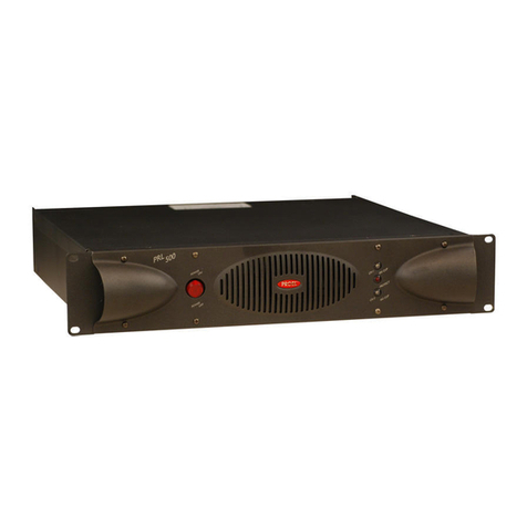
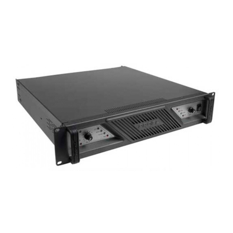
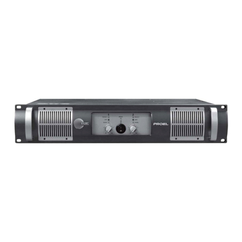
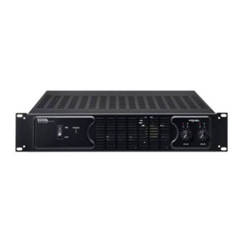
PROEL PRL250 User manual

MADE IN ITALYwww.proelgroup.com
PRL SERIES AMPLIFICATORI DI POTENZA
POWER AMPLIFIERS
ETAPAS DE POTENCIA
MANUALE D’USO • USER’S MANUAL • MANUAL DEL USUARIO

2
INDICE Italiano
AVVERTENZE …………………………………… Pag. 3
INFORMAZIONI GENERALI …………… »4
PRL600 - PRL950 - PRL1400 ……… »6
- Pannello frontale …………………… »6
- Pannello posteriore ………………… »7
- Modalità di funzionamento …… »8
• Modalità “Stereo” ……………… »8
• Modalità “Parallel” ……………… »8
• Modalità “Bridge” ……………… »9
• Modalità “Bi-Amp” ……………… »9
- Circuito OSC™ …………………………… »10
- Connettori ……………………………… »10
- Configurazione interna …………… »11
- Specifiche tecniche…………………… »11
PRL250 ………………………………………… »12
- Pannello frontale …………………… »12
- Pannello posteriore ………………… »13
- Circuito OSC™ …………………………… »13
- Modalità di funzionamento …… »14
• Modalità “Stereo” ……………… »14
• Modalità “Parallel” ……………… »14
• Modalità “Bridge” ……………… »14
- Connettori ……………………………… »15
- Specifiche tecniche ………………… »15
SCHEMI A BLOCCHI ……………………… »16
CONFIGURAZIONI CONSIGLIATE …»17
DICHIARAZIONE DI CONFORMITÀ »18
INDEX English
SAFETY AND PRECAUTIONS …………… Pag. 3
GENERAL INFORMATION ……………… »4
PRL600 - PRL950 - PRL1400 ……… »6
- Front panel ……………………………… »6
- Rear panel ……………………………… »7
- Operating modes ……………………… »8
• “Stereo” mode ……………………… »8
• “Parallel” mode …………………… »8
• “Bridge” mode ……………………… »9
• “Bi-Amp” mode …………………… »9
- OSC™ circuit……………………………… »10
- Connectors ……………………………… »10
- Internal configuration …………… »11
- Technical data…………………………… »11
PRL250 ………………………………………… »12
- Front panel ……………………………… »12
- Rear panel ……………………………… »13
- OSC™ circuit……………………………… »13
- Operating mode ……………………… »14
• “Stereo” mode ……………………… »14
• “Parallel” mode …………………… »14
• “Bridge” mode …………………… »14
- Connectors ……………………………… »15
- Technical data ………………………… »15
BLOCK DIAGRAMS ………………………… »16
SUGGESTED CONFIGURATIONS …… » 17
DECLARATION OF CONFORMITY …… »18
INDICE Español
ADVERTENCIAS DE SEGURIDAD …… Pag. 3
INFORMACIONES GENERALES ……… »4
PRL600 - PRL950 - PRL1400 ……… »6
- Panel delantero ……………………… »6
- Panel trasero …………………………… »7
- Modos de funcionamiento ……… »8
• Modo “Stereo” …………………… »8
• Modo “Parallel” …………………… »8
• Modo “Bridge” …………………… »9
• Modo “Bi-Amp” …………………… »9
- Circuito OSC™ …………………………… »10
- Conectores ……………………………… »10
- Configuración interna ……………… »11
- Especificaciones técnicas ………… »11
PRL250 ………………………………………… »12
- Panel delantero ……………………… »12
- Panel trasero …………………………… »13
- Circuito OSC™ …………………………… »13
- Modos de funcionamiento ……… »14
• Modo “Stereo” …………………… »14
• Modo “Parallel” …………………… »14
• Modo “Bridge” …………………… »14
- Conectores ……………………………… »15
- Especificaciones técnicas ………… »15
DIAGRAMAS DE BLOQUES …………… »16
CONFIGURACIONES ACONSEJADAS »17
DECLARACION DE CONFORMIDAD …»18
INDICE
INDEX
INDICE
PRL SERIES

AVVERTENZE Italiano
• ATTENZIONE
Durante le fasi di uso o manutenzione, devo-
no essere prese alcune precauzioni onde evi-
tare danneggiamenti alle strutture meccani-
che ed elettroniche del prodotto.
Prima di utilizzare il prodotto, si prega di
leggere le seguenti istruzioni. Prendere
visione del manuale d’uso e conservarlo per
successive consultazioni.
- In presenza di bambini, controllare che il
prodotto non rappresenti un pericolo.
- Posizionare l’apparecchio al riparo dagli
agenti atmosferici e a distanza di sicurez-
za dall’acqua e da luoghi ad alto grado di
umidità.
- Non avvicinare il prodotto a fonti di calo-
re (radiatori, fari, etc.).
- Evitare che qualsiasi sostanza liquida vada
all’interno del prodotto.
I terminali marcati con il simbolo sono
attivi e pericolosi ed il cablaggio esterno,
collegato a questi terminali, richiede l’in-
stallazione da parte di persone qualificate o
l’utilizzo di cablaggi già pronti all’uso
Collegare il prodotto ad una linea di alimen-
tazione adeguata facendo uso del cavo rete
in dotazione, controllando sempre che sia in
buono stato:
- Fare attenzione che il punto di alimenta-
zione sia dotato di una efficiente presa di
terra.
- Disconnettere il cavo rete se non viene
usato per un lungo periodo di tempo.
In caso di guasto o manutenzione questo
prodotto deve essere ispezionato da perso-
nale qualificato quando:
- Ci sono difetti sulle connessioni o sui cavi
di collegamento.
- Sostanze liquide penetrano all’interno del
prodotto.
- Il prodotto è caduto e si è danneggiato.
Non intervenire sul prodotto.
Rivolgersi a un centro di assistenza autoriz-
zato Proel.
3
SAFETY AND PRECAUTIONS English
• CAUTION
When using any electric product, basic pre-
cautions should always be taken, including
the following.
Read the instructions, before using the pro-
duct and retain them for future reference.
- To reduce the risk, close supervision is
necessary when the product is used near
children.
- Protect the apparatus from the atmosphe-
ric agents and do not use it near water or
high humidity places.
- This product should be situated away from
heat sources as radiators or other devices
which produce heat.
- Care should be taken so that objects do
not fall onto and liquids are not spilled
inside the product.
The terminals marked with the symbol
are active and dangerous. Any cables con-
nected to these terminals must either be
prefabricated cables approved for this use,
or be installed by qualified personnel.
Connect the apparatus to a power supply
only with the power cord included:
- Make sure that the power supply has a
ground connection in working order.
- The power supply cord should be unplug-
ged from the outlet when left unused for
a long period of time.
In case of fault or maintenance this product
should be serviced only by qualified service
personnel when:
- There is a flaw either in the connections or
in the connecting cables.
- Liquids have spilled inside the product.
- The product has been dropped or the
enclosure is damaged.
Any other servicing should be done by a
qualified technician or by PROEL Service
Department.
ADVERTENCIAS DE SEGURIDAD Español
• ATENCION
Durante las fases de uso o mantenimiento,
se tienen que tomar unas precauciones para
evitar daños a las estructuras mecánicas y
electrónicas del producto.
Lean las siguientes instrucciones antes de
utilizar el aparato. Guardar este manual para
consultas sucesivas.
- En presencia de niños, averigüen que el
producto no represente un peligro.
- Protejan el aparato contra los agentes
atmosféricos, el agua y los lugares con alto
grado de humedad.
- Coloquen el aparato lejos de fuentes de
calor (radiadores, focos, etc.).
- Eviten que cualquier sustancia líquida
penetre al interior del aparato.
Los terminales marcados con el símbolo
son activos y peligroso, y los cables exter-
nos, conectados con estos terminales, debe
ser instalado por personal cualificado o es
necesario utilizar cables pre-hechos.
Conecten el aparato a una línea de alimenta-
ción adecuada utilizando el cable de línea
incluido, averiguando siempre que esté en
buen estado:
- Asegúrense que el punto de alimentación esté
dotado de una eficiente toma de tierra.
- Desconecten el cable de línea en caso que-
dase inutilizado durante mucho tiempo.
En caso de avería o mantenimiento, este
aparato tiene que ser inspeccionado por per-
sonal calificado cuando:
- Se averigüen defectos en las conexiones o
en los cables de conexión.
- Sustancias líquidas penetren al interior del
aparato.
- El aparato se caiga y se dañe.
No intervengan en el producto.
Dirígense a un Centro Asistencia
Autorizado Proel.
AVVERTENZE
SAFETY AND PRECAUTIONS
ADVERTENCIAS DE SEGURIDAD PRL SERIES
Per evitare rischi di folgorazione non aprire
l’apparecchio. Per prevenire rischi di incen-
dio o di scosse elettriche non esporre l’am-
plificatore a pioggia o umidità.
ATTENZIONE
To reduce the risk of electric shock do not
open this apparatus.
To prevent fire or shock hazard do not expo-
se the amplifier to rain or moisture.
CAUTION
Para evitar riesgos de elecrocución no abran
el aparato. Para prevenir riesgos de incen-
dios o de descargas eléctricas no expongan
la etapa de potencia a lluvia o humedad.
ATENCION

INFORMAZIONI GENERALI
GENERAL INFORMATIONS
INFORMACIONES GENERALES
4
PRL SERIES
INFORMAZIONI GENERALI Italiano
• DESCRIZIONE
Proel è orgogliosa di presentare la nuova
linea PRL di amplificatori di potenza profes-
sionali, frutto di un’intensa e meticolosa
ricerca stilistica e funzionale confluita in
una serie di prodotti di alta qualità ed affi-
dabilità, fondamentali sia per le installazio-
ni fisse che per le applicazioni “on the road”.
Le prestazioni dei nuovi finali di potenza
PRL sono tali da soddisfare una vastissima
gamma di applicazioni: dall’home recording
professionale al tour più impegnativo.
La serie PRL è costituita da quattro modelli:
PRL1400, PRL950, PRL600 (con dimensioni
di 2 unità rack standard) e PRL250 (da 1
unità rack standard). Gli amplificatori offro-
no due canali indipendenti realizzati con
dispositivi bipolari in configurazione com-
plementare; due sezioni di alimentazione ad
alta energia garantiscono un ottimo fattore
di smorzamento e una riproduzione senza
eguali delle basse frequenze.
L’esclusivo circuito OSC™ (Output Sense
Clipping) garantisce sull’uscita dell’amplifi-
catore un segnale non distorto in qualsiasi
condizione del segnale di ingresso o di ali-
mentazione di rete. Nella fase di costruzione
degli amplificatori PRL vengono applicate le
norme EN 60065, EN 60335-1, EN 60204-1,
con apparecchio di prova GLP2 60204.
• IMBALLO
L’imballo è stato sottoposto a test di inte-
grità secondo la procedura ISTA 1A.
Si raccomanda di controllare l’amplificatore
subito dopo l’apertura dell’imballo. Se ven-
gono riscontrati danni informare immediata-
mente il rivenditore. Conservare quindi l’im-
ballo completo per permetterne l’ispezione.
Proel declina ogni responsabilità per danni
causati dal trasporto.
• SPEDIZIONI E RECLAMI
Le merci sono vendute “franco nostra sede”
e viaggiano sempre a rischio e pericolo del
distributore.
Eventuali avarie e danni dovranno essere
contestati al vettore.
Ogni reclamo per imballi manomessi dovrà
essere inoltrato entro 8 giorni dal ricevi-
mento della merce.
• GARANZIE E RESI
Gli amplificatori PRL1400, PRL950, PRL600 e
PRL250 sono tutti provvisti della garanzia di
funzionamento e di conformità alle proprie
specifiche, come dichiarate dal costruttore.
La garanzia di funzionamento è di 24 mesi
dopo la data di acquisto.
I difetti rilevati entro il periodo di garanzia
sui prodotti venduti, attribuibili a materiali
GENERAL INFORMATION English
• DESCRIPTION
Proel proudly introduces the new PRL profes-
sional power amplifiers, engineered for sonic
value and reliability both on the road and in
fixed installations.
The powerful performance of the PRL ampli-
fiers satisfies an exceptionally wide range of
amplification needs: from studio reference
monitoring to live touring.
The PRL series consists four models:
PRL1400, PRL950, PRL600 (made in 2 stan-
dard rack units) and PRL250 (made in 1
standard rack unit).
The amplifiers feature bi-polar devices in
complementary configuration, two indipen-
dent channels with separate oversize power
supplies for superior bass performance and
high damping factor.
The exclusive OSC™ circuit (Output Sense
Clipping) gives an undistorted output signal
in any input signal or AC power supply con-
dition.
EN 60065, EN 60335-1, EN 60204-1 norms
are applied during the manufacturing of PRL
amplifiers, through the GLP2 60204 testing
appliance.
• PACKING
The packing of this product has undergone
an integrity test according to ISTA 1A pro-
cedure.
It is recommended to inspect the amplifier
after the unpacking.
If any damage is found, notify immediately
your dealer.
Then save the complete packing for inspec-
tion. Proel declines every responsibility for
damage caused by transport.
• SHIPMENTS AND CLAIMS
The goods are sold “ex works” and always
travel at the risk and danger of the distribu-
tor.
Eventual damage will have to be contested
to the freight forwarder.
Every claim for broken packs will have to be
forwarded within 8 days from the reception
of the goods.
• GUARANTEES AND RETURNS
The amplifiers PRL1400, PRL950, PRL600
and PRL250 are all provided with a guaran-
tee of operation and conformity to their
own data sheets, as declared by the manu-
facturer.
The operation guarantee is for 24 months
after the purchase date.
Defects attributable to defective materials or
defects of construction found within the
period of the guarantee on the sold products,
must be reported in a timely manner to the
INFORMACIONES GENERALES Español
• DESCRIPCION
Proel está orgullosa de introducir su nueva
línea PRL de etapas de potencia profesiona-
les, resultado de una intensa y meticulosa
investigación estilística y funcional conflui-
da en una serie de productos de alta calidad
y fiabilidad, fundamentales tanto para las
instalaciones fijas tanto para las aplicacio-
nes “on the road”. Las prestaciones de las
nuevas etapas de potencia PRL son tales que
pueden satisfacer una amplia gama de apli-
caciones: del home recording profesional a
la gira más gravosa.
La serie PRL está constituida por cuatro
modelos: PRL1400, PRL950, PRL600 (con
dimensiones de 2 unidades rack estándar) y
PRL250 (de 1 unidad rack estándar).
Las etapas de potencia ofrecen dos canales
independientes realizados con dispositivos
bipolares en configuración complementar;
dos secciones de alimentación de alta
energía garantizan un excelente factor de
amortiguación y una reproducción sin igua-
les de las bajas frecuencias. El exclusivo cir-
cuito OSC™ (Output Sense Clipping) garanti-
za una señal sin distorsión en la salida de la
etapa de potencia en cualquier condición de
la señal de entrada o de alimentación de
línea.
En la fase de construcción de las etapas de
potencia PRL, se aplican las normas EN
60065, EN 60335-1, EN 60204-1, con apara-
to de comprobación GLP2 60204.
• EMBALAJE
El embalaje está sometido a prueba de inte-
gridad según el procedimiento ISTA 1A. Se
recomienda controlar la etapa de potencia
inmediatamente después de la abertura del
embalaje. Si se verifican daños, informar
inmediatamente el revendedor. Guardar
entonces el embalaje completo para permitir
su inspección.
Proel declina de cualquier responsabilidad
por daños causados por el transporte.
• EXPEDICIONES Y RECLAMOS
La mercancía se vende “franco fábrica” y
viaja siempre por cuenta y riesgo del distri-
buidor. Eventuales averías y daños tendrán
que ser reclamados al transportador. Cada
reclamo por embalajes dañados tendrá que
ser enviado dentro de 8 días del recibo de la
mercancía.
• GARANTIAS Y RENDIDOS
Las etapas de potencia PRL1400, PRL950,
PRL600 y PRL250 poseen la garantía de fun-
cionamiento y de conformidad a sus propias
especificaciones, como declaradas por el
constructor.
INFORMAZIONI GENERALI
GENERAL INFORMATIONS
INFORMACIONES GENERALES
5
difettosi o difetti di costruzione, devono
essere tempestivamente segnalati al proprio
rivenditore o distributore, allegando eviden-
za scritta della data di acquisto e descrizio-
ne del tipo di difetto riscontrato. Sono
esclusi dalla garanzia difetti causati da uso
improprio o manomissione.
Proel SpA constata tramite verifica sui resi la
difettosità dichiarata, correlata all’appro-
priato utilizzo, e l’effettiva validità della
garanzia; provvede quindi alla sostituzione o
riparazione dei prodotti, declinando tuttavia
ogni obbligo di risarcimento per danni diret-
ti o indiretti eventualmente derivanti dalla
difettosità.
• INSTALLAZIONE
L’installazione del prodotto è prevista su
rack 19” (ventilato) per prodotti ad uso pro-
fessionale.
• LIMITAZIONI D’USO
L’amplificatore è destinato esclusivamente
ad un utilizzo specifico di tipo sonoro:
- collegamento di diffusori passivi e trasfor-
matori di linea a tensione costante;
- segnali di ingresso di tipo audio
(20Hz-20kHz).
Proel declina ogni responsabilità per danni
a terzi causati da mancata manutenzione,
manomissioni, uso improprio o installa-
zione non eseguita secondo le norme di
sicurezza.
dealer or distributor, enclosing written evi-
dence of the purchase date and written
description of the type of defect found. The
guarantee excludes defects caused by impro-
per use or tampering.
Proel SpA will verify the validity of the gua-
rantee claim through examination of the
defect. Proel SpA will eventually provide for
the replacement or repair of the products
declining, however every obligation of com-
pensation for direct or indirect damage
resolving from the defective state.
• INSTALLATION
The product is adapted for installation in a
properly ventilated, standard professional
19” rack.
• LIMITATIONS OF USE
The amplifier is destined exclusively to spe-
cific audio applications:
- connection of passive loudspeakers and
constant voltage line transformers;
- audio input signals (20Hz-20kHz).
Proel declines every responsibility for
damages to third parties caused from lack of
maintenance, manipulations, improper use
or installation without following the safety
regulations.
La garantía de funcionamiento es de 24
meses después de la fecha de compra.
Los defectos averiguados dentro del período
de garantía sobre los productos vendidos,
atribuibles a materiales defectuosos o defec-
tos de construcción tendrán que ser tempe-
stivamente indicados a su propio revendedor
o distribuidor adjuntando evidencia escrita
de la fecha de compra y descripción del tipo
de defecto averiguado. Se excluyen de la
garantía defectos causados por uso impropio
o manipulación.
Proel SpA comprueba la anomalía declarada
sobre los rendidos, asociada a la utilización
apropiada, y a la efectiva validez de la
garantía; entonces se encarga de la sustitu-
ción o reparación de los productos, decli-
nando no obstante de cualquier compromiso
de indemnización contra daños directos o
indirectos en caso de eventual anomalía.
• INSTALACIÓN
La instalación prevista del producto es sobre
rack 19” (ventilado) para productos de uso
profesional.
• LIMITACIONES DE UTILIZACIÓN
La etapa de potencia está destinada exclusi-
vamente para una utilización específica de
tipo sonoro:
- conexión de difusores pasivos y transfor-
madores de línea de voltaje constante;
- señales de salida de tipo audio
(20Hz-20kHz).
Proel declina de cualquier responsabilidad
por daños a terceros causados por carencia
de mantenimiento, perjuicio, uso impropio
o instalación no efectuada según las normas
de seguridad.
PRL SERIES

6
PANNELLO FRONTALE Italiano
INTERRUTTORE
Interruttore di accensione e spegnimento
dell’amplificatore. Se l’amplificatore
non funziona controllare
l’integrità del fusibile di alimentazione
all’interno dell’apparecchio.
INDICATORI DI SEGNALE a LED bicolore
Il LED di colore verde indica il funziona-
mento regolare dell’amplificatore.
Il LED di colore rosso indica che il sistema
OSC™ (Output Sense Clipping) sta interve-
nendo o che il segnale in uscita è in
distorsione (nel caso in cui il dispositivo
OSC™ sia stato disinserito tramite l’inter-
ruttore posto sul retro).
INDICATORE DI MODALITÀ “BRIDGE”
Il LED acceso indica che, tramite l’inter-
ruttore posto sul retro, l’amplificatore è in
modalità “Bridge”.
INDICATORE DI PROTEZIONE
Il LED acceso indica che l’amplificatore è
in protezione per uno dei seguenti motivi:
- temperatura interna elevata;
- tensione continua sull’uscita;
- sovraccarico o cortocircuito sui morsetti
di uscita;
- accensione ritardata di 3 sec.
In caso di accensione dell’indicatore di
protezione verificare che l’amplificatore
abbia un’adeguata areazione (in caso di
surriscaldamento l’amplificatore uscirà
automaticamente dallo stato di protezione
dopo il raffreddamento), che non vi siano
cortocircuiti sulle connessioni delle usci-
te, che il carico sulle uscite non sia infe-
riore a 4Ω(in modalità Stereo e Parallel)
o inferiore a 8Ω(in modalità Bridge).
Effettuati tutti i controlli, se l’amplifica-
tore permane nello stato di protezione, si
prega di contattare un centro di assisten-
za autorizzato Proel.
FRONT PANEL English
POWER SWITCH
Amplifier On/Off switch. If theamplifier
doesn't work, please
check the integrity of the
mains fuse inside the apparatus.
BI-COLOUR LED SIGNAL INDICATORS
Green colour LED indicates the amplifier is
working normally.
Red colour LED indicates OSC™ system
(Output Sense Clipping) is operating or
output signal is distorting (in case OSC™
has been previously disconnected using
the switch placed on the rear panel).
“BRIDGE” MODE INDICATOR
When LED is on, the amplifier is in the
“Bridge” mode using the rear panel
switch.
PROTECTION INDICATOR
When LED is on, the amplifier is being
protected for one of the following rea-
sons:
- overheating;
- output continuous voltage;
- output overload or short circuit;
- soft-start delayed 3 sec.
In case protection indicator is on, make
sure that the amplifier has a proper venti-
lation (in case of overheating, the ampli-
fier will automatically leave protection
mode after cooling), that there are no
short circuits on output connections, that
output load is not inferior to 4Ω(in
Stereo & Parallel mode) or inferior to 8Ω
(in Bridge mode).
Once all checks have been made, if the
amplifier is still in the protection mode,
please contact a Proel Authorized
Customer Service Centre.
PANEL DELANTERO Español
INTERRUPTOR
Interruptor de encendido y apa-
gado de la etapa de potencia. Si la etapa
de potencia no se enciende,
controlen la integridad del fusible de ali-
mentación en la parte interna del aparato.
INDICADORES DE SEÑAL DE LED BICOLOR
El LED de color verde indica el funciona-
miento normal de la etapa de potencia.
El LED de color rojo indica que el sistema
OSC™ (Output Sense Clipping) está ope-
rando o que la señal en salida está en
distorsión (en caso el dispositivo OSC™
haya sido desconectado por medio del
interruptor colocado en la parte trasera).
INDICADOR DE MODALIDAD “BRIDGE”
El LED encendido indica que, por medio del
interruptor colocado en el panel trasero, la
etapa de potencia está en modo “Bridge”.
INDICADOR DE PROTECCION
El LED encendido indica que la etapa de
potencia está bajo protección por una de
las siguientes motivaciones:
- sobrecalentamiento;
- tensión continua en la salida;
- sobrecarga o corto circuito en las salidas;
- encendido retrasado de 3 segundos.
En caso de encendido del indicador de pro-
tección, averiguar que la etapa de potencia
tenga una adecuada ventilación (en caso de
sobrecalentamiento la etapa de potencia
saldrá automáticamente del estado de pro-
tección después de la refrigeración), que no
hayan cortocircuitos en las conexiones de
las salidas, que la carga en las salidas no
sea inferior a 4Ω(en modo Stéreo y
Parallel) o inferior a 8Ω(en modo Bridge).
Una vez efectuados todos los controles, si la
etapa de potencia se queda en el estado de
protección, se ruega contactar un Centro de
Asistencia Autorizado Proel.
PANNELLO FRONTALE
FRONT PANEL
PANEL DELANTERO
PRL600 - PRL950 - PRL1400
PRL1400
POWER ON
14
3
2
1
2
3
4
2
3
4
2
3
4
1 1

PANNELLO POSTERIORE
REAR PANEL
PANEL TRASERO
7
PRL600 - PRL950 - PRL1400
PANNELLO POSTERIORE Italiano
CONTROLLI DI VOLUME
Controlli di volume indipendenti per CH1 e
CH2. Regolazione da -∞a 0dB.
INGRESSI
Ingressi bilanciati con Jack stereo da 1/4”
e XLR. La presa Jack è collegata in paral-
lelo con la presa XLR.
PULSANTI “STEREO”, “PARALLEL”, “BRIDGE”
Selettore per le modalità “Stereo”,
“Parallel” e “Bridge”.
PULSANTE “BI-AMP”
Selettore per inserire il crossover elettro-
nico interno (125Hz-24dB/oct) e permet-
tere all’amplificatore di lavorare in bi-
amplificazione (CH1-Low, CH2-High).
OSC™ON/OFF
Selettore per disinserire il circuito OSC™
(Output Sense Clipping).
PULSANTE “GROUND LIFT”
Selettore per sollevare il contatto di terra
dal circuito audio.
USCITE DI POTENZA CH1 E CH2
Uscite di potenza su 2 connettori SPK4MP
e su 2 morsetti a serrare. I sistemi acusti-
ci utilizzati non devono avere un’impe-
denza inferiore a 4Ω.
USCITA DI POTENZA “BRIDGE”
Uscita di potenza Bridge su un connetto-
re SPK4MP e su morsetti a serrare. Il siste-
ma acustico utilizzato non deve avere
un’impedenza inferiore a 8Ω.
VENTILAZIONE FORZATA
Gli stadi di potenza vengono raffreddati
con una ventola a velocità variabile. Non
ostruire la presa d’aria frontale e i fori d’u-
scita posteriori.
CAVO DI ALIMENTAZIONE
Cavo di alimentazione completo di spina
per 230V AC o 115V AC 50Hz-60Hz.
PUSH PUSH
11
66 13 12 11
10
14
5 5
7 9 11 1112
8
5
6
7
8
9
10
11
12
13
14
11
12
13
14
11
12
13
14
5
6
7
8
9
10
REAR PANEL English
VOLUME CONTROLS
Independent volume controls for CH1 and
CH2. Adjustable from -∞to 0dB.
INPUTS
Balanced inputs with 1/4” stereo jack and
XLR-F connectors. The Jack socket and the
XLR-F socket are connected in parallel.
“STEREO”, “PARALLEL”AND “BRIDGE”MODE
Push buttons for the selection of “Bridge”
mode and “Parallel” mode.
“BI-AMP”SELECTOR
The button enables to connect the
built-in electronic crossover (125Hz-
12dB/oct) for bi-amplification
(CH1-Low, CH2-High).
OSC™ON/OFF
Push button for the selection of the OSC™
(Output Sense Clipping) circuit.
“GROUND LIFT”SELECTOR
Selector to lift the ground from the audio
circuit.
CH1 AND CH2 STEREO OUTPUTS
Power output is on 2 SPK4MP connectors
and on 2 binding posts. The nominal
impedance of loudspeaker enclosure must
not be less than 4Ω.
“BRIDGE”OUTPUT
Bridge mono power output is on a SPK4MP
connector and binding posts. The nominal
impedance of loudspeaker enclosure must
not be less than 8Ω.
FORCED VENTILATION
Power stages are cooled by a variable
speed fan. Do not obstruct the frontal
ventilation grill or the rear output screen.
MAINS CABLE
Mains cable complete with plug for 230V
AC or 115V AC 50Hz-60Hz.
PANEL TRASERO Español
CONTROLES DE VOLUMEN
Controles de volumen independientes para
CH1 y CH2. Ajuste de -∞a 0dB.
ENTRADAS
Entradas balanceadas con Jack estéreo de
1/4” y XLR-F. La base Jack está conectada
en paralelo con la base XLR.
PULSADORES “STEREO”, “PARALLEL”Y “BRIDGE”
Selector para los modos “Stereo”, “Parallel”
y “Bridge” de la etapa de potencia.
PULSADOR “BI-AMP”
Selector para activar el crossover electró-
nico interno (125Hz-12dB/oct) y permitir
a la etapa de potencia de operar en bi-
amplificación (CH1-Low, CH2-High).
CONTROL OSC™
Selector para desactivar el circuito OSC™
(Output Sense Clipping).
PULSADOR “GROUND LIFT”
Selector para excluir el contacto de tierra
del circuito audio.
SALIDAS DE POTENCIA CH1 Y CH2
Salidas de potencia en 2 conectores
SPK4MP y en 2 bornes para apretar. La
impedancia nominal de los sistemas acú-
sticos utilizados no debe ser inferior a 4Ω.
SALIDA DE POTENCIA “BRIDGE”
Salida de potencia Bridge en un conector
SPK4MP y en bornes para apretar. La impe-
dancia nominal del sistema acústico utili-
zado no debe ser inferior a 8Ω.
VENTILACION FORZADA
Los estadios de potencia están refrigera-
dos por un ventilador de velocidad varia-
ble. No obstruyan la toma de aire frontal y
los agujeros de salida traseros.
CABLE DE ALIMENTACION
Cable de alimentacion completo de clavija
para 230V AC o 115V AC 50Hz-60Hz.
5
6
7
8
9
10

8
MODALITÀDI FUNZIONAMENTO
OPERATING MODES
MODOS DE FUNCIONAMIENTO
PRL600 - PRL950 - PRL1400
MODALITÀ“STEREO”Italiano
• I due canali CH1 e CH2 lavorano con due
segnali d’ingresso indipendenti. I pulsanti
“Bridge” e “Parallel” devono essere sollevati.
“STEREO”MODE English
• The two channels CH1 and CH2 operate with
two independent signals. The “Bridge” and
“Parallel” switches are in up position.
MODO “STEREO”Español
• Los dos canales CH1 y CH2 operan con dos
señales de entrada independientes. Los pulsa-
dores “Bridge” y “Parallel” se deben desactivar.
PUSH PUSH
a a
a
b b
b
FROM MIXER
STEREO
AMPLIFIER
STEREO MODE
Input
Input
Output
Output
CH1
CH2
PUSH PUSH PUSH PUSH
MODALITÀ“PARALLEL”Italiano
• Il segnale in ingresso su CH1 pilota entram-
bi i canali dell’amplificatore, regolati separa-
tamente dai 2 controlli di volume. Il pulsan-
te “Parallel” deve essere premuto.
“PARALLEL”MODE English
• The signal fed in CH1 drives the 2 amplifier
channels with different levels regulated by
the 2 volume controls. The “Parallel” switch
must be pushed down.
MODO “PARALLEL”Español
• La señal en entrada en CH1 dirige ambos
canales de la etapa de potencia, regulados
separadamente por los dos controles de volu-
men. El pulsador “Parallel” se debe activar.
PUSH PUSH
FROM MIXER
PARALLEL
(mono)
AMPLIFIER
PARALLEL MODE
Input Output
Output
CH1
CH2
a a
a
b b
b
PUSH PUSH PUSH PUSH

9
MODALITÀDI FUNZIONAMENTO
OPERATING MODES
MODOS DE FUNCIONAMIENTO PRL600 - PRL950 - PRL1400
MODALITÀ“BRIDGE”Italiano
• L’amplificatore è monofonico, con l’ingresso
su CH1 e l’uscita sul connettore “Bridge” o
sui morsetti “Bridge”. Il pulsante “Bridge”
deve essere premuto. L’impedenza di carico e
la potenza di uscita raddoppiano.
“BRIDGE”MODE English
• The amplifier operates in mono. Signal on
CH1, output on Bridge binding posts and
the Bridge switch is down.
The load impedance and the output deli-
vered are doubled.
MODO “BRIDGE”Español
• La etapa de potencia está monofónica, con la
entrada en CH1 y la salida en el conector
“Bridge” o en los bornes “Bridge”. El pulsador
“Bridge” tiene que estar activado. La impedan-
cia de carga y la potencia de salida se doblan.
PUSH PUSH
BRIDGE
AMPLIFIER
BRIDGE MODE
Input Output
Output
CH1
CH2
a
a
b
PUSH PUSH
FROM MIXER
b
PUSH PUSH
MODALITÀ“BI-AMP”Italiano
• L’amplificatore lavora in Bi-Amplificazione
con LOW su CH1 e HIGH su CH2, quando i
pulsanti “Bi-Amp” e “Parallel” sono pre-
muti.
“BI-AMP”MODE English
• The amplifier works in Bi-Amplification with
CH1 on the Low and CH2 on the High, when
the “Bi-Amp” and “Parallel” switches are
pushed down.
MODO “BI-AMP”Español
• La etapa de potencia opera en Bi-
Amplificación con CH1 en Low y CH2 en
High, cuando los pulsadores “Bi-Amp” y
“Parallel” están activados.
PUSH PUSH
b b
PARALLEL
(mono)
BI-AMP
AMPLIFIER
BI-AMP MODE
Input Output
high
low
Output
CH1
CH2
FROM MIXER a a
ab
PUSH PUSH PUSH PUSH

10
OSC™- CONNETTORI
OSC™- CONNECTORS
OSC™- CONECTORES
PRL600 - PRL950 - PRL1400
OSC™Italiano
• CIRCUITO DI CONTROLLO
DELLA SATURAZIONE
Il circuito OSC™ permette all’amplificatore
di funzionare al limite della saturazione,
senza mai arrivare alla squadratura.
Il circuito controlla in tempo reale che la
forma d’onda del segnale sia sempre sinusoi-
dale, sia in presenza di un eccessivo segna-
le in ingresso, sia in presenza di una tensio-
ne di alimentazione variabile rispetto al
valore nominale di 230V AC o 115V AC fino
al 25% in meno. È possibile escludere il cir-
cuito OSC™. In tal caso fare attenzione che
un segnale di uscita eccessivamente distor-
to non danneggi gli altoparlanti.
OSC™Español
•CIRCUITO DE CONTROL DE RECORTE
El circuito OSC™ permite a la etapa de
potencia de funcionar al límite de recorte sin
llegar nunca a la distorsión.
El circuito controla en tiempo real que la
forma de onda de la señal sea siempre sinu-
soidal, tanto en presencia de una excesiva
señal en entrada, tanto en presencia de un
voltaje de alimentación variable en relación
con el valor nominal de 230V AC o 115V AC
hasta el 25% menos.
El circuito OSC™ se puede excluir. En este
caso tener cuidado para que una señal de
salida excesivamente distorsionada no dañe
los altavoces.
1
2
3
XLR balanced
2-positive / 3-negative / 1-ground
XLR unbalanced
2-positive / 3-negative connected to 1-ground
JACK balanced
Tip-positive / Ring-negative / Sleeve-ground
JACK unbalanced
Tip-positive / Ring-negative connected
to Sleeve-ground
OSC™English
•OUTPUT SENSE CLIPPING
The OSC™ circuit allows the amplifier to
work within the clipping limit, avoiding the
creation of distortion square waves.
The circuit controls in real time that the
signal is always sinusoidal, either when the
input signal is too high or when the mains
power is variable compared to the 230V AC
or 115V AC nominal values till 25% less.
It is possible to exclude the OSC™ circuit.
In this condition be advised that the loud-
speakers may be damaged by an excessively
distorted output signal.
CONNETTORI Italiano CONECTORES EspañolCONNECTORS English
Input
Input
Output
Output
CH1
CH2
OFF
ON
+12dB
+12dB
OSC™
OSC™
3 4
1 2
+12dB sinusoidal input signal. OSC™ off.
Output signal with clipping.
+12dB sinusoidal input signal. OSC™ on.
Output signal without clipping.
1
2
3
4
OSC™
OFF
{
OSC™
ON
{
POWER CONNECTOR
1+ / 1- connected
2+ / 2- not connected

11
CONFIGURAZIONE INTERNA - SPECIFICHE TECNICHE
INTERNAL CONFIGURATION - TECHNICAL DATA
CONFIGURACION INTERNA - ESPECIFICACIONES TECNICAS PRL600 - PRL950 - PRL1400
CONFIGURAZIONE INTERNA Italiano
•SENSIBILITÀ
È possibile selezionare la sensibilità di
ingresso spostando i due jumper JS3 e JS6
(posizione 0 o posizione +4) sul circuito
stampato dell’amplificatore:
posizione 0 0dB / 0.775V (default)
posizione +4 +4dB / 1.24V
•BI-AMP - Tabella delle frequenze
Il crossover interno è del tipo Linkwitz-Riley
24dB/oct. È possibile variare la frequenza di
taglio cambiando il valore di alcune resi-
stenze (di precisione, da 1/4W), in base alla
tabella.
Il valore preimpostato è 125Hz.
Le configurazioni devono essere effettuate
soltanto da personale qualificato o da un
centro di assistenza autorizzato Proel.
INTERNAL CONFIGURATION English
•SENSITIVITY
It is possible to select the input sensitivity
changing the position of JS3 and JS6 jum-
pers (0 position or +4 position) on the
amplifier pc board:
position 0 0dB / 0.775V (default)
position +4 +4dB / 1.24V
•BI-AMP - Frequency tables
The internal crossover is a 24dB/oct
Linkwitz-Riley type. It is possibile to chan-
ge the cutoff frequency modifying the value
of some resistors (precision type, 1/4W)
referring to the table.
The factory value is 125Hz.
Configurations must be made only by quali-
fied personnel or by Proel service depart-
ment.
FREQUENCY R1,R2,R3, R6, R7
R4,R5,R8
Ft = 80Hz 13kΩ27kΩ
Ft = 100Hz 11kΩ22kΩ
Ft = 125Hz 9kΩ18kΩ
Ft = 140Hz 8k2Ω16kΩ
Ft = 160Hz 6k8Ω13kΩ
PRL600 PRL950 PRL1400
Output power (THD<1% 1kHz)
Stereo 8+8Ω190W+190W 300W+300W 430W+430W
Stereo 4+4Ω300W+300W 475W+475W 700W+700W
Bridge Mono 16Ω300W 475W 700W
Bridge Mono 8Ω600W 950W 1400W
Frequency response (± 0.5dB) 20Hz-20kHz
Input sensitivity: 0dB or +4dB
Input impedance: 20kΩbalanced / 10kΩunbalanced
Damping factor: >500 @ 4Ω
S/N ratio: (unweighted) >100dB >102.5dB >104dB
Input connectors: XLR and Stereo Jack 1/4”
Output connectors: SPK4MP (1+/1-) and Binding posts
Cooling: 1 x variable speed DC Fan
PRL600 PRL950 PRL1400
Indicators (LED) Green/Red for Signal/Clip
Red for Protect
Green for “Bridge” mode
Protections: DC - Thermal - Soft Start - Short circuit
OSC™ Output Sense Clipping (switchable)
Power supply 230V AC - 50Hz or 117V AC - 60Hz
Mains fuse T5A 230V T8A 230V T8A 230V
T10A 117V T15A 117V T15A 117V
Max power consumption 1000VA 1800VA 2600VA
Dimensions: WxHxD 483x88.3x444mm
Weight: 17kg - 37.5lbs 21kg - 46lbs 23kg - 51lbs
Shipping: 17.8kg 23.7kg 24.5kg
0.072cbm 0.072cbm 0.072cbm
77mm
32.5mm
433mm
88.3mm
444mm
432mm
483mm
Misure di potenza effettuate secondo le norme AES.
Power measurements refer to AES standards.
Medidas de potencia realizadas en conformidad con las normas AES.
CONFIGURACION INTERNA Español
•SENSIBILIDAD
Es posible seleccionar la sensibilidad de
entrada moviendo los jumpers JS3 y JS6
(posición 0 o posición +4) sobre el circuito
impreso de la etapa de potencia:
posición 0 0dB / 0.775V (default)
posición +4 +4dB / 1.24V
•BI-AMP - Tabla de las frecuencias
El crossover interno es de tipo Linkwitz-Riley
24dB/oct. Es posibile variar la frecuencia de
corte modificando el valor de algunas resi-
stencias (de precisión, de 1/4W) con refe-
rencia a la tabla.
El valor predefinido es 125Hz.
Las configuraciones tienen que ser realiza-
das sólo por personal cualificado o por un
centro de asistencia autorizado Proel.
SPECIFICHE TECNICHE Italiano TECHNICAL DATA English ESPECIFICACIONES TECNICAS Español

12
PANNELLO FRONTALE
FRONT PANEL
PANEL DELANTERO
PRL 50
PANNELLO FRONTALE Italiano
INTERRUTTORE
Interruttore di accensione e spegnimento
dell’amplificatore.
INDICATORI DI SEGNALE A LED BICOLORE
Il LED di colore verde indica il funziona-
mento regolare dell’amplificatore.
Il LED di colore rosso indica che il sistema
OSC™ (Output Sense Clipping) sta interve-
nendo.
INDICATORE DI PROTEZIONE
Il LED acceso indica che l’amplificatore è
in protezione per uno dei seguenti motivi:
- temperatura interna elevata;
- tensione continua sull’uscita;
- sovraccarico o cortocircuito sui morsetti
di uscita;
- accensione ritardata di 3 sec.
In caso di accensione dell’indicatore di
protezione verificare che l’amplificatore
abbia un’adeguata areazione e che i fori
per il raffreddamento a convezione, posti
sulla parte superiore e lateralmente, non
siano ostruiti (in caso di surriscaldamento
l’amplificatore uscirà automaticamente
dallo stato di protezione dopo il raffred-
damento). Controllare inoltre che non vi
siano cortocircuiti sulle connessioni delle
uscite, che il carico sulle uscite non sia
inferiore a 4Ω(in modalità Stereo e
Parallel) o inferiore a 8Ω(in modalità
Bridge). Effettuati tutti i controlli, se
l’amplificatore permane nello stato di pro-
tezione, si prega di contattare un centro
di assistenza autorizzato Proel.
CONTROLLI DI VOLUME
Controlli di volume indipendenti per CH1 e
CH2 con regolazione da -∞a 0dB.
FRONT PANEL English
POWER SWITCH
Amplifier On/Off switch.
BI-COLOUR LED SIGNAL INDICATORS
Green colour LED indicates the amplifier is
working normally.
Red colour LED indicates OSC™ system
(Output Sense Clipping) is operating.
PROTECTION INDICATOR
When LED is on, the amplifier is being
protected for one of the following rea-
sons:
- overheating;
- output continuous voltage;
- output overload or short circuit;
- soft-start delayed 3 sec.
In case protection indicator is on, make
sure that the amplifier has a proper venti-
lation and the convection cooling vent
outlets, situated on the top and on the
sides, are not obstructed (in case of
overheating, the amplifier will automati-
cally leave protection mode after coo-
ling).
Also verify that there are no short circuits
on output connections, that output load
is not inferior to 4Ω(in Stereo & Parallel
mode) or inferior to 8Ω(in Bridge mode).
Once all checks have been made, if the
amplifier is still in the protection mode,
please contact a Proel Authorized
Customer Service Centre.
VOLUME CONTROLS
Independent volume controls for CH1 and
CH2. Adjustable from -∞to 0dB.
PANEL DELANTERO Español
INTERRUPTOR
Interruptor de encendido y apagado de la
etapa de potencia.
INDICADORES DE SEÑAL DE LED BICOLOR
El LED de color verde indica el funciona-
miento normal de la etapa de potencia.
El LED de color rojo indica que el sistema
OSC™ (Output Sense Clipping) está ope-
rando.
INDICADOR DE PROTECCION
El LED encendido indica que la etapa de
potencia está bajo protección por una de
las siguientes motivaciones:
- sobrecalentamiento;
- tensión continua en la salida;
- sobrecarga o corto circuito en los bornes
de salida;
- encendido retrasado de 3 segundos.
En caso de encendido del indicador de pro-
tección, averiguar que la etapa de potencia
tenga una adecuada ventilación y que los
agujeros de refrigeración por convección,
colocados en la parte superior y lateralmen-
te, no estén obstruidos (en caso de sobre-
calentamiento la etapa de potencia saldrá
automáticamente del estado de protección
después de la refrigeración), controlar
además que no hayan cortocircuitos en las
conexiones de las salidas, que la carga en
las salidas no sea inferior a 4Ω(en modo
Stéreo y Parallel) o inferior a 8Ω(en modo
Bridge). Una vez efectuados todos los con-
troles, si la etapa de potencia se queda en
el estado de protección, se ruega contactar
un Centro de Asistencia Autorizado Proel.
CONTROLES DE VOLUMEN
Controles de volumen independientes para
CH1 y CH2 con ajuste de -∞a 0dB.
1
2
3 3
444
3
1
2
1
2

13
PANNELLO POSTERIORE
REAR PANEL
PANEL TRASERO PRL 50
5 8 10
7 96
PANNELLO POSTERIORE Italiano
INGRESSI
Ingressi bilanciati con Jack stereo da
1/4” e sbilanciati su pin-RCA.
PULSANTE “STEREO/BRIDGE”
Selettore per le modalità “Stereo” e
“Bridge”.
PULSANTE “STEREO/PARALLEL”
Selettore per le modalità “Stereo” e
“Parallel”.
USCITE DI POTENZA CH1 E CH2
Uscite di potenza su 2 connettori a 4 poli
SPK4MP collegati su 1+/1-. L’impedenza
nominale dei sistemi acustici utilizzati
non deve essere inferiore a 4Ω.
USCITA DI POTENZA “BRIDGE”
Uscita di potenza “Bridge” sui morsetti a
serrare (rosso+/nero-). L’impedenza nomi-
nale del sistema acustico utilizzato non
deve essere inferiore a 8Ω.
PRESA DI ALIMENTAZIONE
Presa a vaschetta con fusibile di protezio-
ne. In caso di rottura sostituire con fusi-
bile ritardato da 5x20mm, T2A (230V) o
T4A (115V).
REAR PANEL English
INPUTS
1/4” Jack stereo balanced inputs and
RCA-pins unbalanced inputs.
“STEREO/BRIDGE”SELECTOR
Switch selector for “Stereo” and “Bridge”
mode.
“STEREO/PARALLEL”SELECTOR
Switch selector for “Stereo” and “Parallel”
mode.
CH1 AND CH2 POWER OUTPUTS
Power outputs on two 4-poles SPK4MP
connectors, connected on 1+/1-. The
nominal impedance of loudspeaker enclo-
sure must not be less than 4Ω.
“BRIDGE”POWER OUTPUT
Power outputs on the binding posts
(red+/black-), connected on 1+/1-. The
nominal impedance of loudspeaker enclo-
sure must not be less than 8Ω.
MAINS SOCKET
AC socket with protection fuse.
If the fuse blows it must be replaced with
delayed fuse 5x20mm, T2A (230V) or T4A
(115V).
PANEL TRASERO Español
ENTRADAS
Entradas balanceadas con Jack estéreo de
1/4” y no balanceadas en pin-RCA.
PULSADOR “STEREO/BRIDGE”
Selector para los modos “Stereo” y
“Bridge”.
PULSADOR “STEREO/PARALLEL”
Selector para los modos “Stereo” y
“Parallel”.
SALIDAS DE POTENCIA CH1 Y CH2
Salidas de potencia en dos conectores de
cuatro polos SPK4MP, conectados en 1+/1.
La impedancia nominal de los sistemas acú-
sticos utilizados no debe ser inferior a 4Ω.
SALIDA DE POTENCIA “BRIDGE”
Salida de potencia “Bridge” en los bornes
para apretar (rojo+/negro-). La impedan-
cia nominal del sistema acústico utilizado
no debe ser inferior a 8Ω.
TOMA DE ALIMENTACION
Toma AC con fusible de protección.
En caso de rotura sustituir con fusible
retrasado de 5x20mm, T2A (230V) o T4A
(115V).
5
6
7
8
9
10
6
7
8
9
10
6
7
8
9
10
5 5
OSC™Italiano
•CIRCUITO DI CONTROLLO
DELLA SATURAZIONE
Il circuito OSC™ controlla in tempo reale che
il segnale non saturi mai, sia in presenza di
un eccessivo segnale in ingresso, sia in pre-
senza di una tensione di alimentazione
variabile rispetto al valore nominale di 230V
AC o 115V AC fino al 25% in meno.
OSC™Español
•CIRCUITO DE CONTROL DE RECORTE
El circuito OSC™ controla en tiempo real
que la señal no sature nunca, tanto en
presencia de una excesiva señal en entra-
da, tanto en presencia de un voltaje de
alimentación variable en relación con el
valor nominal de 230V AC o 115V AC hasta
el 25% menos.
OSC™English
•OUTPUT SENSE CLIPPING
The OSC™ controls in real time that the
signal never clips, either when the input
signal is too high or when the mains power
is variable compared to the 230V AC or 115V
AC nominal values till 25% less.
Input Output
OSC™
with OSC™: no clipping
Input Output
without OSC™: clipping

14
MODALITÀDI FUNZIONAMENTO
OPERATING MODES
MODOS DE FUNCIONAMIENTO
PRL 50
FROM MIXER
STEREO
AMPLIFIER
STEREO MODE
Input
Input
Output
Output
CH1
CH2
MODALITÀ“STEREO”Italiano
• I due canali CH1 e CH2 lavorano con due
segnali di ingresso indipendenti. I pulsanti
“Bridge” e “Parallel” devono essere alzati.
“STEREO”MODE English
• The two channels CH1 and CH2 operate with
two independent input signals. The switches
“Bridge” and “Parallel” are in up position.
MODO “STEREO”Español
• Los dos canales CH1 y CH2 operan con dos
señales de entrada independientes. Los pulsa-
dores “Bridge” y “Parallel” se deben desactivar.
FROM MIXER
PARALLEL
AMPLIFIER
PARALLEL MODE
Input Output
Output
CH1
CH2
MODALITÀ“PARALLEL”Italiano
• Il segnale in ingresso su CH1 pilota entram-
bi i canali dell’amplificatore, regolati separa-
tamente dai 2 controlli di volume. Il pulsan-
te “Parallel” deve essere premuto.
“PARALLEL”MODE English
• The signal fed in CH1 drives the 2 amplifier
channels with different levels regulated by
the 2 volume controls. The “Parallel” switch
must be pushed down.
MODO “PARALLEL”Español
• La señal de entrada en CH1 dirige ambos
canales de la etapa de potencia, regulados
separadamente por los dos controles de volu-
men. El pulsador “Parallel” se debe activar.
FROM MIXER
BRIDGE
AMPLIFIER
BRIDGE MODE
Input Output
Output
CH1
CH2
MODALITÀ“BRIDGE”Italiano
• L’amplificatore è monofonico, con l’ingresso
su CH1 e l’uscita sui morsetti “Bridge”. Il pul-
sante “Bridge” deve essere premuto.
L’impedenza di carico e la potenza di uscita
raddoppiano.
“BRIDGE”MODE English
• The amplifier operates in mono. Signal on
CH1, output on Bridge binding posts and
the “Bridge” switch is down. The load
impedance and the output delivered are
doubled.
MODO “BRIDGE”Español
• La etapa de potencia está monofónica, con la
entrada en CH1 y la salida en los bornes
“Bridge”. El pulsador “Bridge” tiene que estar
activado. La impedancia de carga y la potencia
de salida se doblan.

15
CONNETTORI - SPECIFICHE TECNICHE
CONNECTORS - TECHNICAL DATA
CONECTORES - ESPECIFICACIONES TECNICAS PRL 50
SPECIFICHE TECNICHE Italiano TECHNICAL DATA English ESPECIFICACIONES TECNICAS Español
43.8 mm
32.5mm
374 mm
384mm
483mm
436mm
32.5mm
RCA-pin unbalanced
positive / ground
JACK balanced
Tip-positive / Ring-negative / Sleeve-ground
JACK unbalanced
Tip-positive / Ring-negative connected
to Sleeve-ground
CONNETTORI Italiano CONECTORES EspañolCONNECTORS English
POWER CONNECTOR
1+ / 1- connected
2+ / 2- not connected
Misure di potenza effettuate secondo le norme AES.
Power measurements refer to AES standards.
Medidas de potencia realizadas en conformidad con las normas AES.
PRL250
Output power (THD<1% 1kHz)
Stereo 8+8Ω80W+80W
Stereo 4+4Ω125W+125W
Bridge Mono 16Ω125W
Bridge Mono 8Ω250W
Frequency response (± 0.5dB) 20Hz-20kHz
Input sensitivity: 0dB
Input impedance: 20kΩbalanced / 10kΩunbalanced
Damping factor: >300 @ 4Ω
S/N ratio: (unweighted) >100dB
Input connectors: Stereo Jack 1/4” and RCA-pins
PRL250
Output connectors: SPK4MP (1+/1-) and Binding posts (Bridge)
Cooling: convection
Indicators (LED) Green/Red for Signal/Clip - Red for Protect
Protections: DC - Thermal - Soft Start - Short circuit
OSC™ Output Sense Clipping
Power supply 230V AC - 50Hz or 117V AC - 60Hz
Mains fuse T2A 230V / T4A 117V
Max power consumption 500VA
Dimensions: WxHxD 483x43.8x384mm
Weight: 9.5kg - 21lbs
Shipping: 10.4kg / 0.037cbm

16
SCHEMI A BLOCCHI
BLOCK DIAGRAMS
DIAGRAMA DE BLOQUES
PRL SERIES
230/117V AC
CROSSOVER
IN
CH1
IN
CH2
CROSSOVER
THERMAL
PROTECTION
CH2
SUPPLY CH1
SUPPLY
AMP
SENSE
LIMITER
SENSE
LIMITER
AMP POWER AMP
POWER AMP
OUT
CH1
OUT
CH2
INPUT
BALANCED/UNBALANCED
INPUT
BALANCED/UNBALANCED
230/117V AC
IN
CH1
IN
CH2
THERMAL
PROTECTION
CH2
SUPPLY CH1
SUPPLY
AMP
SENSE
LIMITER
SENSE
LIMITER
AMP POWER AMP
POWER AMP
OUT
CH1
OUT
CH2
INPUT
BALANCED/UNBALANCED
INPUT
BALANCED/UNBALANCED
SCHEMA A BLOCCHI Italiano
• PRL1400
• PRL950
• PRL600
BLOCK DIAGRAM English
• PRL1400
• PRL950
• PRL600
DIAGRAMA DE BLOQUES Español
• PRL1400
• PRL950
• PRL600
SCHEMA A BLOCCHI Italiano
• PRL250
BLOCK DIAGRAM English
• PRL250
DIAGRAMA DE BLOQUES Español
• PRL250

PRL250 PRL600 PRL950 PRL1400
NEXT series 2 x NEXT12P8 2 x NEXT12HP8 4 x NEXT12HP8
2 x NEXT12HP4
TFLV/TFL series 2 x TFL10P 4 x TFL10P 4 x TFL12P8
2 x TFL12P4 2 x TFL12P8 2 x TFL15P8
2 x TFL15P4 2 x TFL212P4
2 x TFL115SP4 2 x TFL115SP8
1 x TFL215SP8 (Bridge) 1 x TFL218SP8 (Bridge)
TPRMARKII series 2 x TPRK8P 4 x TPRK8P 4 x TPRK10P 4 x TPRK15P8
2 x TPRK10P 2 x TPRK12P8 2 x TPRK153P8
2 x TPRK12P4 4 x TPRK12P8 4 x TPRK153P8
2 x TPRK15P4 2 x TPRK15P8 4 x TPRK15MP
1 x TPRK118SP8 (Bridge) 2 x TPRK153P8 2 x TPRK118SP4
2 x TPRK15MP
SMARTPLUS series 2 x SMT10P 4 x SMT10P 2 x SMT15P8 2 x SMT153P8
2 x SMT12P 2 x SMT12P 4 x SMT15P8 4 x SMT153P8
2 x SMT12MP 4 x SMT12P 2 x SMT153P8 4 x SMT15SP8
2 x SMT15P4 2 x SMT215P4 2 x SMT18SP8
2 x SMT12MP 2 x SMT15MP
2 x SMT12SP8 4 x SMT15MP
2 x SMT15SP4 2 x SMT15SP8
2 x SMT18SP4
SPARK series 4 x SPARK65PG
4 x SPARK65PW
EDGE series 2 x EDGE8CXP 4 x EDGE8CXP
17
CONFIGURAZIONI CONSIGLIATE
SUGGESTED CONFIGURATIONS
CONFIGURACIONES ACONSEJADAS PRL SERIES
CONFIGURAZIONI Italiano
CONSIGLIATE SUGGESTED English
CONFIGURATIONS CONFIGURACIONES Español
ACONSEJADAS
•SISTEMI A TENSIONE COSTANTE
Utilizzando gli amplificatori PRL insieme ai
trasformatori di linea a tensione costante
(70V/100V) TRL è possibile connettere più
diffusori con trasformatore di linea a tensio-
ne costante.
La somma delle potenze dei diffusori con-
nessi non deve superare la potenza di uscita
dell’amplificatore e del trasformatore:
•TRL150.4 + 2xPRL600 max 150W (4CH)
•TRL300.2 + 1xPRL950 max 300W (2CH)
•TRL600.2 + 1xPRL1400 max 600W (2CH)
• CONSTANT VOLTAGE SYSTEMS
Using the PRL amplifiers with the TRL con-
stant voltage transformers (70V/100V), it is
possible to connect several speakers with
constant voltage transformer.
The total power of connected loudspeakers
must not exeed the amplifier’s and transfor-
mer’s output power:
•TRL150.4 + 2xPRL600 max 150W (4CH)
•TRL300.2 + 1xPRL950 max 300W (2CH)
•TRL600.2 + 1xPRL1400 max 600W (2CH)
•SISTEMAS DE VOLTAJE CONSTANTE
Utilizando las etapas de potencia PRL con
los transformadores de línea de voltaje con-
stante (70V/100V) TRL es posible conectar
varios difusores con transformador de línea
de voltaje constante.
La suma de las potencias de los difusores
conectados no debe exceder la potencia de sali-
da de la etapa de potencia y del transformador:
•TRL150.4 + 2xPRL600 max 150W (4CH)
•TRL300.2 + 1xPRL950 max 300W (2CH)
•TRL600.2 + 1xPRL1400 max 600W (2CH)

DICHIARAZIONE DI CONFORMITÀ
Il produttore:
PROEL S.P.A. - Via alla Ruenia, 37/43 - 64027 Sant’Omero (Te) - Italy
Dichiara sotto la propria responsabilità che il prodotto:
AMPLIFICATORE DI POTENZA
Modello:
PRL250 –PRL600 –PRL950 –PRL1400
è conforme alla Direttiva 89/336/CEE (Compatibilità Elettromagnetica)
e successive modifiche 92/31/CEE e 93/68/CEE, secondo i seguenti standard:
EN 50082-1:1997, EN 55013:1990, EN 55020:1994
inoltre, è conforme alla Direttiva 73/23/CEE (Bassa Tensione)
e successive modifiche 93/68/CEE, secondo il seguente standard:
EN 60065:1998
DECLARATION OF CONFORMITY
The manufacturer:
PROEL S.P.A. - Via alla Ruenia, 37/43 - 64027 Sant’Omero (Te) - Italy
Declares under the own responsability that the product:
POWER AMPLIFIER
Model:
PRL250 –PRL600 –PRL950 –PRL1400
is in compliance with Directive 89/336/EEC (Electromagnetic Compatibility)
and successive modifications 92/31/EEC and 93/68/EEC, as the following standards:
EN 50082-1:1997, EN 55013:1990, EN 55020:1994
it is also in compliance with Directive 73/23/EEC (Low Voltage)
and successive modifications 93/68/EEC, as the following standard:
EN 60065:1998
DECLARACION DE CONFORMIDAD
El productor:
PROEL S.P.A. - Via alla Ruenia, 37/43 - 64027 Sant’Omero (Te) - Italy
Declara bajo su propia responsabilidad que el producto:
ETAPA DE POTENCIA
Modelo:
PRL250 –PRL600 –PRL950 –PRL1400
está conforme a la directiva 89/336/CEE (Compatibilidad Electromagnética)
y sucesivas modificaciones 92/31/CEE y 93/68/CEE, según los siguientes estándares:
EN 50082-1:1997, EN 55013:1990, EN 55020:1994
además, está conforme a la directiva 73/23/CEE (Bajo Voltaje)
y sucesivas modificaciones 93/68/CEE, según el siguiente estándar:
EN 60065:1998
PROEL S.p.A.

www.proelgroup.com
is a registered trade mark
Tutte le specifiche possono essere variate senza alcuna notifica.
Design and specifications subject to change without notice.
Todas las especificaciones están sujetas a cambio sin previo aviso.

PROEL International Ltd.
Units 7&8, Windsor Centre
Windsor Grove, West Norwood
London SE27 9LT - UK
Tel.: +44 20 8761 9911
Fax: +44 20 8761 9922
E-mail: info@proelint.co.uk
www.proelint.co.uk
PROEL USA Inc.
945 B Pendale
El Paso TX 79907 - USA
Phone: +1 915 591 5848
Fax: +1 915 591 5849
E-mail: [email protected]
PROEL FRANCE s.a.r.l
Z.A. La Stée
57560 St. Quirin - FRANCE
Tel.: +33 3 87 0866 84
Fax: +33 3 87 0861 93
E-mail: proel.fr[email protected]
PROELUSA PRODUTOS
MUSICAIS LDA
Quinta Casal Raposa-Armazém D
Alto da Venda Nova
2305 - 302 Casais Tomar PORTUGAL
Tel.: +351 249 301722 - +351 249 301728
Fax: +351 249 301754
E-mail: [email protected]
PROEL BENELUX b.v.
Bas Van Den Broek - Baronieweg 13
5321 JV Hedel - NEDERLAND
Tel.: +31 0 73599 6171
Fax: +31 0 73599 5946
E-mail: info@basvandenbroek.com
www.basvandenbroek.com
PROEL KOREA CO. LTD.
176-5 Youngcheon-Ri Okcheon-Meon
Yangpoung-Kun Kyunggi-Do – SOUTH KOREA
Tel.: +82 2 3442 7098
Fax: +82 2 3442 7318
E-mail: info@proelkorea.com
www.proelkorea.com
PROEL S.p.A.
(World Headquarters - Factory)
Via alla Ruenia, 37/43 - 64027 Sant’Omero (Te) - ITALY
Tel: +39 0861 81241 - Fax: +39 0861 887862
E-mail: info@proelgroup.com
www.proelgroup.com
This manual suits for next models
3
Table of contents
Other PROEL Amplifier manuals

PROEL
PROEL PREW User manual

PROEL
PROEL AMP120XL User manual

PROEL
PROEL AMP 240Z4 User manual

PROEL
PROEL ACDT180V User manual

PROEL
PROEL HPAMP104 User manual

PROEL
PROEL TUBE100USB User manual

PROEL
PROEL HP-X series User manual

PROEL
PROEL HP-X 6000 User manual

PROEL
PROEL ACDT90 User manual

PROEL
PROEL AMP03VR User manual