PROEL FLASH15HDA User manual

FLASH15HDA
acve processed loudspeaker
USER MANUAL
MANUALE D'USO

FCC COMPLIANCE NOTICE
This device complies with part 15 of the FCC rules. Operaon is subject to the following two condions:
(1) This device may not cause harmful interference, and
(2) this device must accept any interference received, including interference that may cause undesired operaon.
CAUTION: Changes or modificaons not expressly approved by the party responsible for compliance could void
the user’s authority to operate the equipment.
NOTE: This equipment has been tested and found to comply with the limits for a Class B digital device, pursuant to
part 15 of the FCC Rules. These limits are designed to provide reasonable protecon against harmful interference in
a residenal installaon. This equipment generates, uses, and can radiate radio frequency energy and, if not installed
and used in accordance with the instrucon manual, may cause harmful interference to radio communicaons.
However, there is no guarantee that interference will not occur in a parcular installaon. If this equipment does
cause harmful interference to radio or television recepon, which can be determined by turning the equipment off
and on, the user is encouraged to try to correct the interference by one or more of the following measures:
• Reorient or relocate the receiving antenna.
• Increase the separaon between the equipment and receiver.
• Connect the equipment into an outlet on a circuit different from that to which the receiver is connected.
• Consult the dealer or an experienced radio/TV technician for help.
This marking shown on the product or its literature, indicates that it should not be disposed with other household wastes at the end of
its working life. To prevent possible harm to the environment or human health from uncontrolled waste disposal, please separate this
from other types of wastes and recycle it responsibly to promote the sustainable reuse of material resources. Household users should
contact either the retailer where they purchased this product, or their local government office, for details of where and how they can
take this item for environmentally safe recycling. Business users should contact their supplier and check the terms and condions of the
purchase contract. This product should not be mixed with other commercial wastes for disposal.
The lightning flash with arrowhead symbol within an equilateral triangle is intended to alert the user to the presence of uninsulated
“dangerous voltage” within the product’s enclosure, that may be of sufficient magnitude to constute a risk of electric shock to persons.
The exclamaon point within an equilateral triangle is intended to alert the user to the presence of important operang and maintenance
(servicing) instrucons in the literature accompanying the appliance.
The informaon contained in this publicaon has been carefully prepared and checked. However no responsibility will be taken for any errors. All
rights are reserved and this document cannot be copied, photocopied or reproduced in part or completely without wrien consent being obtained
in advance from PROEL. PROEL reserves the right to make any aesthec, funconal or design modificaon to any of its products without any prior
noce. PROEL assumes no responsibility for the use or applicaon of the products or circuits described herein.
Il marchio riportato sul prodoo o sulla documentazione indica che il prodoo non deve essere smalto con altri rifiudomesci al
termine del ciclo di vita. Per evitare eventuali danni all’ambiente si invita l’utente a separare questo prodoo da altri pi di rifiue di
riciclarlo in maniera responsabile per favorire il riulizzo sostenibile delle risorse materiali. Gli utendomesci sono invitaa contaare
il rivenditore presso il quale è stato acquistato il prodoo o l’ufficio locale preposto per tue le informazioni relave alla raccolta
differenziata e al riciclaggio per questo po di prodoo. Gli uten
aziendali sono invitaa contaare il proprio fornitore e verificare i
termini e le condizioni del contrao di acquisto. Questo prodoo non deve essere smalto unitamente ad altri rifiucommerciali.
Il simbolo del lampo con freccia in un triangolo equilatero intende avverre l'ulizzatore per la presenza di "tensioni pericolose" non isolate
all'interno dell'involucro del prodoo, che possono avere una intensità sufficiente a costuire rischio di scossa elerica alle persone.
Il punto esclamavo in un triangolo equilatero intende avverre l'ulizzatore per la presenza di importanistruzioni per l'ulizzo e la
manutenzione nella documentazione che accompagna il prodoo.
Le informazioni contenute in questo documento sono state aentamente redae e controllate. Tuavia non è assunta alcuna responsabilità per
eventuali inesaezze. Tui dirisono riservae questo documento non può essere copiato, fotocopiato, riprodoo per intero o in parte senza
previo consenso scrio della PROEL. PROEL si riserva il dirio di apportare senza preavviso cambiamene modifiche esteche, funzionali o di
design a ciascun proprio prodoo. PROEL non assume alcuna responsabilità sull’uso o sul l’applicazione dei prodoo dei circuiqui descri.

3
INDEX
FCC COMPLIANCE NOTICE . . . . . . . . . . . . . . . . . . . 2
TECHNICAL SPECIFICATIONS . . . . . . . . . . . . . . . . . 3
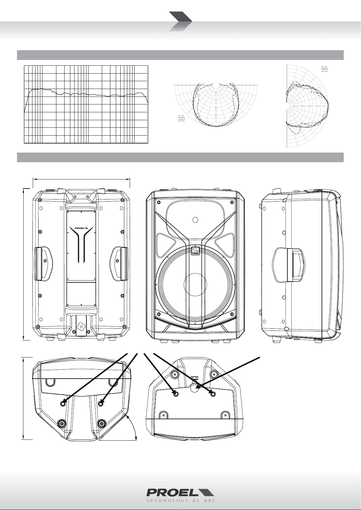
FREQUENCY RESPONSE . . . . . . . . . . . . . . . . . . . . . 4
DIMENSIONS AND FLYING POINTS. . . . . . . . . . . . . 4
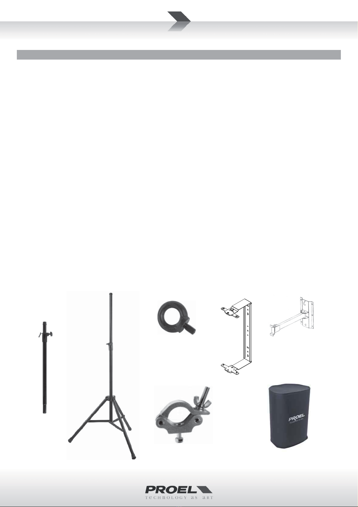
ACCESSORIES . . . . . . . . . . . . . . . . . . . . . . . . . . . . . 5
CONTROL PANEL (FIG.1). . . . . . . . . . . . . . . . . . . . . 6
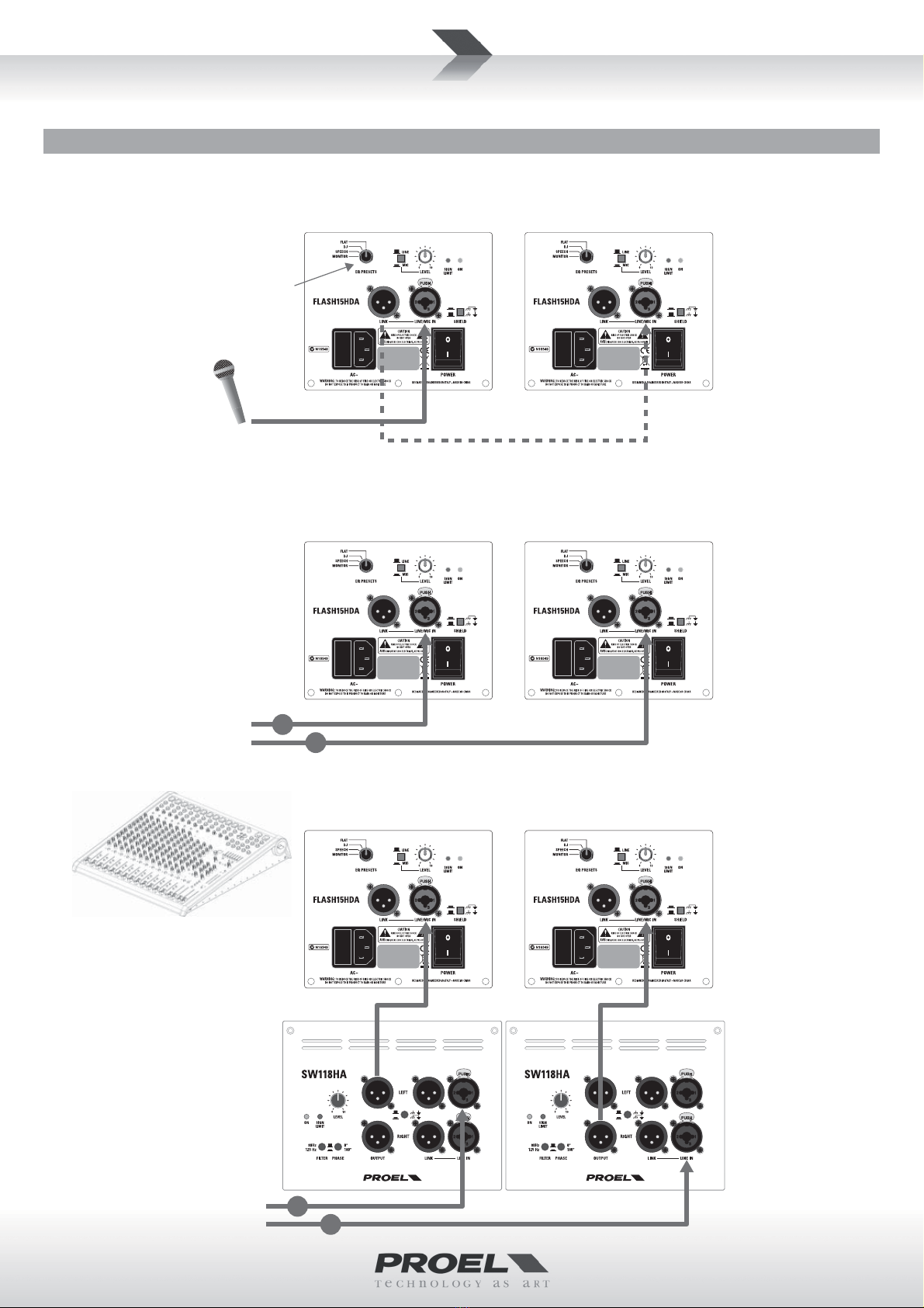
CONNECTIONS (FIG.2) . . . . . . . . . . . . . . . . . . . . . . 6
CONFIGURATION EXAMPLES (FIG.3) . . . . . . . . . . . 7
SAFETY AND PRECAUTIONS . . . . . . . . . . . . . . . . . . 8
IN CASE OF FAULT . . . . . . . . . . . . . . . . . . . . . . . . . . 8
TROUBLESHOOTING . . . . . . . . . . . . . . . . . . . . . . . . 8
CE CONFORMITY. . . . . . . . . . . . . . . . . . . . . . . . . . . 9
PACKAGING, SHIPPING AND COMPLAINT . . . . . . . 9
WARRANTY AND PRODUCTS RETURN . . . . . . . . . . 9
INSTALLATION AND DISCLAIMER . . . . . . . . . . . . . . 9
POWER SUPPLY AND MAINTENANCE . . . . . . . . . . 9
GENERAL INFORMATION . . . . . . . . . . . . . . . . . . . 10
INPUT AND CONTROL INSTRUCTIONS (FIG.1/2/3)10
INDICE
SPECIFICHE TECNICHE . . . . . . . . . . . . . . . . . . . . . . 3
RISPOSTA IN FREQUENZA. . . . . . . . . . . . . . . . . . . . 4
DIMENSIONI E PUNTI DI SOSPENSIONE. . . . . . . . . 4
ACCESSORI . . . . . . . . . . . . . . . . . . . . . . . . . . . . . . . 5
PANNELLO DI CONTROLLO (FIG.1) . . . . . . . . . . . . . 6
CONNESSIONI (FIG.2) . . . . . . . . . . . . . . . . . . . . . . . 6
ESEMPI CONFIGURAZIONI (FIG.3) . . . . . . . . . . . . . 7
AVVERTENZE PER LA SICUREZZA . . . . . . . . . . . . . 12
IN CASO DI GUASTO . . . . . . . . . . . . . . . . . . . . . . . 12
PROBLEMATICHE COMUNI. . . . . . . . . . . . . . . . . . 12
CONFORMITÀ CE. . . . . . . . . . . . . . . . . . . . . . . . . . 13
IMBALLAGGIO, TRASPORTO E RECLAMI . . . . . . . 13
GARANZIE E RESI . . . . . . . . . . . . . . . . . . . . . . . . . 13
INSTALLAZIONE E LIMITAZIONI D’USO. . . . . . . . . 13
ALIMENTAZIONE E MANUTENZIONE . . . . . . . . . . 13
INFORMAZIONI GENERALI . . . . . . . . . . . . . . . . . . 14
ISTRUZIONI INGRESSI E CONTROLLI (FIG.1/2/3) . 14
MODEL FLASH15HDA MODELLO FLASH15HDA
System type 2-way vented Sistema 2 vie bass-reflex
High Frequency Device 1” CELESTION compression driver with 1.75"VC Altoparlante aldriver a compressione 1" CELESTION - 1.75" VC
Low Frequency Device 15” CELESTION woofer with 3"VC Altoparlante bassi woofer 15" CELESTION - 3" VC
Angular Coverage 90° H x 60° V Copertura angolare 90° H x 60° V
Frequency response 45 Hz - 20 kHz Risposta in Frequenza 45 Hz - 20 kHz
Max SPL at 1mt (peak) 129 dBspl SPL massima a 1m (picco) 129 dBspl
Total Peak Power 1200 W Potenza Massima di Picco 1200 W
HF Amplifier Cont. Power 100 W Class AB Potenza Connua Amp. AF 100 W Classe AB
LF Amplifier Cont. Power 500 W Class D Potenza Connua Amp. BF 500 W Classe D
Power supply type SMPS Tipo alimentazione SMPS
Processing 96 KHz, 40 bit floang point CORE DSP Processore DSP 96 KHz, 40 bit floang point CORE DSP
Input Impedance 30 kohm balanced / 15 kohm unbalanced Impedenza ingresso 30 kohm sbilanciato / 15 kohm bilanciato
Input Sensivity LINE: +4 dBu / MIC: +34 dBu Sensibilità nom. ingresso LINE: +4 dBu / MIC: +34 dBu
Controls LEVEL, MIC/LINE selector, PRESET selector (FLAT,
DJ, SPEECH, MONITOR), GND li
Controlli LEVEL, seleore MIC/LINE, seleore PRESET (FLAT,
DJ, SPEECH, MONITOR), GND li
Connectors INPUT: COMBO (XLR-F/JACK)
LINK: XLR-M
Conneori INPUT: COMBO (XLR-F/JACK)
LINK: XLR-M
Power Supply 230 V~ or 120 V~ - 50/60 Hz Tensione alim. di rete 230 V~ o 120 V~ - 50/60 Hz
Maximum Consumpon 650 W Consumo massimo 650 W
Rated Consumpon* 200 W Consumo nominale* 200 W
Construcon Hi density Polypropylene with metal grid Costruzione Polipropilene Alta Densità con Griglia in Metallo
Cabinet Colour Black Colore Nero
Flying System 4 x M10 Sistema di sospensione 4 x M10
Pole Adapter 1 x boom Flangia per suppor1 x soo
Handles 2 x sides, 1 x top Maniglie 2 x ai la, 1 x sopra
Monitor taper 42° Inclinazione monitor 42°
Weight 26.5 Kg (60.6 lb) Peso 26.5 Kg
Dimensions (W x H x D) 470 x 730 x 400 mm Dimensioni (LxAxP) 470 x 730 x 400 mm
* Rated consumpon is measured with pink noise with a crest factor of 12 dB,
this can be considered a standard music program.
* Il consumo nominale è misurato con un rumore rosa con un faore di cresta
di 12 dB, considerato come un programma standard di musica.
TECHNICAL SPECIFICATIONS SPECIFICHE TECNICHE

4
FREQUENCY RESPONSE RISPOSTA IN FREQUENZA
DIMENSIONS AND FLYING POINTS DIMENSIONI E PUNTI DI SOSPENSIONE
0
-6
-12
-18
-24
-30
dB
30°
60°
90° -90°
-60°
-30°
2000 Hz
4000 Hz
8000 Hz
16000 Hz
HORIZONTAL
HORN POLAR PLOT
Q = 5.3 DI = 7.3
0
-6
-12
-18
-24
-30
dB 30°
60°
90°
-90°
-60°
-30°
2000 Hz
4000 Hz
8000 Hz
16000 Hz
VERTICAL
HORN POLAR PLOT
Q = 7.0 DI = 8.5
M10 flying points Pole Adaptor
73 cm (29 inch)
47 cm (18.5 inch)
40 cm (15.7 inch)
Monitor Taper 42°
10k5k2k1k500
200
10050
40 20kHz
120.0
dBSPL
110.0
100.0
90.0
80.0
70.0

5
ACCESSORIES
KP210
Adjustable speaker pole for speaker-subwoofer separaon
with terminal pieces Ø 35 mm. Supplied with a bolt
locking mechanism incorporang a steel pin for extra
safety. Adjustment: 825 - 1320 mm.
FRE300BK
Professional aluminium floor-stand for speaker with
terminal pieces Ø 35mm. Supplied with a screw locking
system, a steel safety pin and “Aircushioned” air-damped
release device to grant a flexible, fast and easy adjustment.
Adjustment: 1470-2180 mm.
AC169
Black galvanized steel eyebolt MA10 for flying mount.
KPTFL15
C-shape metal bracket for wall mount with 4 step of 15°
combined with 2 step of 40°.
KPTNX04
Horizontal and Vercal adjustable metal bracket for wall
mount, bar length 25 cm, 12.5° 4 step vert. aiming, 10°
7 step hor. aiming, must be used in conjunction with
KPTFL15.
PLH300
Single aluminium coupler with M12 bolt, always use two
couplers with the KPTFL15 for each speaker.
COVERFL15
Heavy duty cover for carrying.
ACCESSORI
KP210
Supporto distanziatore cassa-subwoofer regolabile in
acciaio con terminali Ø 35mm. Dotato di meccanismo di
chiusura a vite con pin di sicurezza in acciaio. Regolazione:
825 - 1320 mm.
FRE300BK
Supporto professionale in alluminio da pavimento con
terminali Ø 35mm. Con sistema di blocco a vite, pin di
sicurezza in acciaio e disposivo di smorzamento ad aria
per la massima velocità e facilità di regolazione.
Regolazione: 1470-2180 mm.
AC169
Golfare in acciaio zincato nero MA10 per sospensione.
KPTFL15
Supporto in metallo a C per montaggio a muro con 4 passi
da 15° combinabili con 2 passi a 40°.
KPTNX04
Staffa in metallo regolabile in orizzontale e vercale per
montaggio a muro, lunghezza barra 25 cm, 4 passi a 12.5°
in vercale e 7 passi a 10° in orizzontale, deve essere usata
con l'accessorio KPTFL15.
PLH300
Accoppiatore per truss in alluminio con bullone M12,
usarne sempre due insieme all'accessorio KPTFL15.
COVERFL15
Copertura di protezione per il trasporto.
COVERFL15
FRE300BK
PLH300
AC169 KPTNX04
KPTFL15
KP210

6
CONTROL PANEL (FIG.1) PANNELLO DI CONTROLLO (FIG.1)
CONNECTIONS (FIG.2) CONNESSIONI (FIG.2)
INPUT (ingresso)
Jack (bilanciato)
INPUT
Jack (balanced)
sleeve - ground
tip - hot
ring - cold
INPUT (ingresso)
XLR bilanciato maschio
INPUT
Balanced male XLR
ground
hot
cold
INPUT (ingresso)
Jack (sbilanciato)
INPUT
Jack (unbalanced)
ground
tip - hot
cold
*nota: connettere insieme cold e ground
per cavi da bilanciato a sbilanciato
*note: connect both cold and ground
to make cable from balanced to unbalanced
LINK (uscita)
XLR bilanciato femmina
LINK (output)
Balanced female XLR
ground
hot
cold

7
CONFIGURATION EXAMPLES (FIG.3) ESEMPI CONFIGURAZIONI (FIG.3)
PROEL suggested
equipment:
M-series mixer LEFT
FLASH15HDA (sat)
+ SW118HA (sub)
RIGHT
FLASH15HDA (sat)
+ SW118HA (sub)
RIGHT
FLASH15HDA
LEFT
FLASH15HDA
basic system
2x FLASH15HDA
FLASH15HDA
(mic in)
single voice system
FLASH15HDA
(mic in)
single voice system
minimal
conference
system
SUB+SAT system
2x SW118HA
+
2x FLASH15HDA
SET THE EQ PRESET ON “SPEECH”
AND LINE/MIC ON “MIC”
R
L
R
L
dynamic microphone
PROEL suggested types:
DM580 - DM586 - DM226
DM220 - DM800
or
WM wireless mic

8
SAFETY AND PRECAUTIONS
• CAUTION: before using this product read carefully the following safety instrucons. Take a look of this manual enrely and preserve it for
future reference.
When using any electric product, basic precauons should always be taken, including the following:
– To reduce the risk, close supervision is necessary when the product is used near children.
– Protect the apparatus from atmospheric agents and keep it away from water, rain and high humidity places.
– This product should be site away from heat sources such as radiators, lamps and any other device that generate heat.
– This product should be located so that its locaon or posion does not interfere with its proper venlaon and heang dissipaon.
– Care should be taken so that objects and liquids do not go inside the product.
– The product should be connected to a power supply mains line only of the type described on the operang instrucons or as marked on the
product. Connect the apparatus to a power supply using only power cord included making always sure it is in good condions.
– WARNING: The mains plug is used as disconnect device, the disconnect device shall remain readily operable.
– Do not cancel the safety feature assured by means of a polarized line plug (one blade wider than the other) or with a earth connecon.
– Make sure that power supply mains line has a proper earth connecon.
– Power supply cord should be unplugged from the outlet during strong thunderstorm or when leunused for a long period of me.
– Do not place objects on the product’s power cord or place it in a posion where anyone could trip over, walk on or roll anything over it. Do not
allow the product to rest on or to be installed over power cords of any type. Improper installaons of this type create the possibility of fire hazard
and/or personal injury.
– This product may be capable of producing sound levels that could cause
permanent hearing loss. Exposure to extremely high noise levels may cause
permanent hearing loss. Individuals vary considerably in suscepbility to noise-
induced hearing loss, but nearly everyone will lose some hearing if exposed
to sufficiently intense noise for a period of time. The U.S. Government’s
Occupational Safety and Health Administration (OSHA) has specified the
permissible noise level exposures shown in the following chart. According to
OSHA, any exposure in excess of these permissible limits could result in some
hearing loss. To ensure against potenally dangerous exposure to high sound
pressure levels, it is recommended that all persons exposed to equipment
capable of producing high sound pressure levels use hearing protectors while
the equipment is in operaon. Ear plugs or protectors in the ear canals or over
the ears must be worn when operang the equipment in order to prevent
permanent hearing loss if exposure is in excess of the limits set forth here. Keep
your's aenon that children and pets are more suscepble to excessive noise
levels.
IN CASE OF FAULT
• In case of fault or maintenance this product should be inspected only by qualified service personnel when:
– There is a flaw either in the connecons or in the supplied connecng cables.
– Liquids have spilled inside the product.
– The product has fallen and been damaged.
– The product does not appear to operate normally or exhibits a marked change in performance.
– The product has been lost liquids or gases or the enclosure is damaged.
• Do not operate on the product, it has no user-serviceable parts inside, refer servicing to an authorized maintenance centre.
TROUBLESHOOTING
No Power • The loudspeaker's "POWER" switch is off.
• Make sure the mains AC outlet is live (check with a tester or a lamp).
• Make sure the mains plug is securely plugged into mains AC outlet.
No Sound • Is the input LEVEL control for the channel turned up?
• Is the SIGNAL LED illuminated? If not check if your signal level is too low or check the signal cable, mixer and other
equipment seng and cabling.
• Are you sure your signal cables works properly? check it using a cable tester or replacing with a new one.
• Is the SPEAKON cable connector correctly inserted? turn it clockwise unl it clicks.
• Are you sure your power cable works properly? check it using a cable tester or replacing with a new one.
Distorted Sound • Input signal level is too high. Turn down your level controls.
NOTE: The loudspeakers should never be operated at a level which causes the amplifier Clip LEDs to illuminate
constantly.
Different channel
level
• Check if are using a balanced cable for one channel and an unbalanced one for the other, as this would cause a
considerable difference in channel levels.
• Be sure that your loudspeaker system is fully connected and both loudspeakers have the same impedance.
Noise / Hum • Enable GND LIFT buon on rear panel, if the problem persist press all GND LIFT buons for all system's amplifiers.
• Whenever possible, preferably use only balanced cables. Unbalanced lines may also be used but may result in noise
over long cable runs.
• Somemes it helps to plug all audio equipment into the same AC circuit so they share a common ground.
Duraon Per Day
In Hours
Sound Level dBA
Slow Response
Typical
Example
8 90 Duo in small club
692
4 95 Subway Train
397
2 100 Very loud classical music
1.5 102
1 105 Traffic noise
0.5 110
0.25 or less 115 Loudest parts at a rock concert

9
CE CONFORMITY
• Proel products comply with direcve 2004/108/EC (EMC), as stated in EN 55103-1 and EN 55103-2 standards and with direcve 2006/95/CE
(LVD), as stated in EN 60065 standard.
• Under the EM disturbance, the rao of signal-noise will be changed above 10dB.
PACKAGING, SHIPPING AND COMPLAINT
• This unit package has been submied to ISTA 1A integrity tests. We suggest you control the unit condions immediately aer unpacking it.
• If any damage is found, immediately advise the dealer. Keep all unit packaging parts to allow inspecon.
• Proel is not responsible for any damage that occurs during shipment.
• Products are sold “delivered ex warehouse” and shipment is at charge and risk of the buyer.
• Possible damages to unit should be immediately nofied to forwarder. Each complaint for package tampered with should be done within eight
days from product receipt.
WARRANTY AND PRODUCTS RETURN
• Proel products have operang warranty and comply their specificaons, as stated by manufacturer.
• Proel warrants all materials, workmanship and proper operaon of this product for a period of two years from the original date of purchase. If
any defects are found in the materials or workmanship or if the product fails to funcon properly during the applicable warranty period, the owner
should inform about these defects the dealer or the distributor, providing receipt or invoice of date of purchase and defect detailed descripon.
This warranty does not extend to damage resulng from improper installaon, misuse, neglect or abuse. Proel S.p.A. will verify damage on returned
units, and when the unit has been properly used and warranty is sll valid, then the unit will be replaced or repaired. Proel S.p.A. is not responsible
for any "direct damage" or "indirect damage" caused by product defecveness.
INSTALLATION AND DISCLAIMER
• Proel products have been expressly designed for audio applicaon, with signals in audio range (20Hz to 20kHz). Proel has no liability for damages
caused in case of lack of maintenance, modificaons, improper use or improper installaon non-applying safety instrucons.
• The installaon of these speakers is provided for indoors, in case of use outdoors be sure that the speakers are installed correctly in a safe
locaon protected from wind, rain and humidity. To avoid performance deterioraon of mechanical, acouscs and electrical parts is not advisable
to leave these speakers exposed outdoors for a long period of me, so we suggest a temporary installaon for the limited sound events.
• The installaon of these speakers is provided for floor or by means of specific stands able to support their weight. Therefore avoid installaon
on unstable elements such as: furniture, chairs and vibrant surfaces as stages or other speakers without appropriate fix point specifically designed
to avoid speaker movement. Then avoid the use of inadequate supports, we suggest to use PROEL stands and accessories only.
• In case of the speakers are provided of rigging points: DO NOT SUSPEND THE SPEAKERS FROM THE HANDLES, use exclusively these rigging points.
Consult professional rigger or structural engineers prior to suspending loudspeakers from a structure not intended for that use. Always know the
working load limit of the structure supporng the loudspeakers. Always make sure that the rigging hardware minimum rang is at least five mes
the actual load, speakers and rigging hardware.
• In case of suspended installaons of acve loudspeakers where is not possible to turn on and offthe speakers from their appropriate switches,
we recommend to install switches on the mains lines, for this purpose consult an expert electrician for the exact dimension of wiring.
• Locate the speakers as far away as possible from radio or television receivers or other sensive equipment. These speakers have a strong
magnec field which can induce hum and noise into unshielded devices that are located nearby with consequent deterioraon of recepon of
image and sound.
• Proel S.p.A. reserves the right to change these specificaons at any me without noce.
• Proel S.p.A. declines any liability for damages to objects or persons caused by lacks of maintenance, improper use, installaon not performed
with safety precauons and at the state of the art.
POWER SUPPLY AND MAINTENANCE
• Clean only with dry cloth.
• Check periodically that the slots for its proper venlaon and heang dissipaon are not obstructed by dust, remove the dust using a dry brush
or a compressed air gun.
• The amplified loudspeakers of Proel have been designed with CLASS I construcon and must be connected always to a mains socket outlet with
a protecve earth connecon (the third grounding prong).
• Before connecng the product to the mains outlet make certain that the mains line voltage matches that shown on the rear of the product, a
tolerance of up to ±10% is acceptable.
• Inside the amplified loudspeakers are present special safety devices such as:
9Transformer and amplifier over-heang protecon.
9Protecon against excessive power applied at each speaker.
• THE REPLACEMENT OF FUSES INSIDE THE APPARATUS MUST BE MADE ONLY BY QUALIFIED PERSONNEL.
• CHECK THE CONDITION OF THE PROTECTION FUSE, ACCESSIBLE OUTWARD, ONLY WITH THE APPARATUS SWITCHED OFF AND DISCONNECTED
FROM THE MAINS LINE OUTLET.
• REPLACE THE PROTECTION FUSE ONLY WITH SAME TYPE AS SHOWN ON THE PRODUCT.
• IF AFTER THE SUBSTITUTION, THE FUSE INTERRUPTS AGAIN THE APPARATUS WORKING, DO NOT TRY AGAIN THEN CONTACT THE PROEL
SERVICE CENTRE.

10
GENERAL INFORMATION
Thank you for having chosen a PROEL product.
FLASH15HDA is an acve full-range 2-way system featuring high-grade CELESTION transducers and a DSP-controlled
lightweight amplifier module in a sturdy polypropylene cabinet. The transducers employed include a 1” compression
driver with a 1.75" voice coil on a wide constant coverage horn, designed for providing an extended response and low
distoron levels, and a high-power 15” woofer with a 3” voice coil.
The profile of the cabinet allows the use of the enclosure also as a stage monitor, whereas four M10 suspension points
are provided for installaon in a variety of posions using the oponal accessories available. Two convenient aluminium
handles, plus a third on top of the cabinet, make for easy handling and transportaon.
The amplifier module includes a 100 W CLASS AB amplifier for the HF secon and a 500 W CLASS D amplifier with SMPS
for the LF secon. A built-in DSP secon features state-of-the-art signal processing with 40 bit floang point resoluon
and 24 bit AD/DA converters, for a superior sonic performance. Advanced funcons include full parametric EQ for the
system fine tuning, delay lines for speaker alignment, up to 48 dB/oct. crossover filters, three bands of dynamic EQ,
compressors/limiters for protecng the transducers against distoron and power overloads. 4 different PRESETS (FLAT,
DJ, SPEECH, MONITOR) opmized for using the system in different applicaons are also available.
INPUT AND CONTROL INSTRUCTIONS (FIG. 1 / 2 / 3)
1. LINE/MIC IN (combo XLR-JACK input)
This is a female combo connector, which accepts a XLR or a JACK plug from almost any type of equipment with a
balanced or unbalanced outputs. The XLR input is wired as follows:
Pin 1 = shield or ground
Pin 2 = + posive or "hot"
Pin 3 = - negave or "cold"
The JACK input is wired as follows:
Tip = + posive or "hot"
Ring = - negave or "cold"
Sleeve = shield or ground
When connecng an unbalanced signal, wire them as follows:
Pin2 / Tip = + posive or "hot"
Pin 1-3 / Sleeve = shield or ground
NOTE: whenever possible, use always balanced cables. Unbalanced lines may also be used but may result in noise over
long cable runs. In any case, avoid using a balanced cable for one channel and an unbalanced one for the other.
2. LINK (XLR output)
This is a male XLR connector, it is connected in parallel with the respecve LINE IN input, so the LINK is wired as LINE IN
input. Connect these to the inputs of other powered speakers to make an array.
3. GND LIFT switch
This switch lithe ground of the balanced audio inputs from the earth-ground of the amplifier. If you have HUM noise
problem on one or more loudspeaker try to change the posion of these switches (oen all up or all down for all the
amplifiers in the system). Please note that to have an effect all cables must be balanced.
4. MIC / LINE switch
This switch adjusts the gain of the LINE/MIC input varying the sensivity between MIC, suited to connect a microphone,
and LINE, suited to connect a device with high level output like a MIXER, a CD player etc.
NOTE: do not use the MIC sensivity to "pump up" the volume with the LINE level equipment, in order to avoid the AD
converter saturaon that could produce very annoying distoron.
5. LEVEL control
Rotary level control: it aenuates the level of the signal sent to the LINE input. The aenuaon ranges from “0” fully
closed (the signal is completely aenuated) to “10” fully open, nominal level (the signal is not aenuated in any way,
so is fed to the internal amplifier at the same level at which it arrives on input).

11
6. PRESET selector
This switch allows the selecon between four different DSP sengs (equalisaon curves, dynamics etc.), suited to four
different uses.
FLAT
Suited for live sound reinforcement, this preset includes a dynamic equalizer.
When the system is used at low or mid level, the deep lows and the top highs are
enhanced, resulng in an deep and detailed response, ideal for the reproducon
vocals and live instruments. When the level of the signal sent to the amplifier is
increased and it approaches the limiter acon, the enhancement of low and high
frequencies is reduced, thus increasing the dynamics and the efficiency of the
whole system. Together with that, the mid-high frequencies are slighlty decreased,
thus reducing the harshness that can occur when the sound is very loud and
making it more enjoyable.
DJ
Suited for the reproducon of recorded music, this preset includes a dynamic
equalizer.
When the system is used at low or mid level, the deep lows and the top highs are
enhanced, resulng in an richer and brighter response, ideal for the reproducon
of background music or for a DJ set. When the level of the signal sent to the
amplifier is increased and it approaches the limiter acon, the enhancement of low
and high frequencies is reduced, thus increasing the dynamics and the efficiency
of the whole system. Together with that, the mid-high frequencies are slightly
decreased, thus reducing the harshness that can occur when the sound is very loud
and making it more enjoyable.
SPEECH
This preset has been designed for applicaons (such as conferences) where a
dynamic microphone is directly connected to the speaker input and it provides the
correct equalizaon for enhancing the human voice intelligibility.
MONITOR
Suited for the use of the system as a stage monitor, in this preset the deep lows
are aenuated in order to compensate the floor posion, the mid-low frequencies
are enhanced for a beer presence and the mid-high frequencies are reduced for
an improved feedback rejecon.
7. SIGN / LIMIT indicator
GREEN LED illuminates to indicate the presence of the signal at the amplifier
input.
RED LED illuminates when the internal amplifier's output is limited or when the
input AD converter clips.
NOTE: When this LED flashes reduce the input signal level.
NOTE: If you hear annoying and excessive distoron check the MIC/LINE switch posion, most probably you are sending
to the speaker a high line level signal using the MIC sensivity, so switch it to LINE sensivity.
8. ON indicator
GREEN LED: when lighted indicates that the amplifier has been turned on and AC power is available.
9. POWER switch
Speaker is "ON" when the switch is in the "I" posion.
NOTE: When you shut down your equipment, turn offthe speaker first. When powering up, turn on the speaker last.
10. AC~ socket
Here’s where you plug in your speaker’s mains supply cord. You should always use the mains cord supplied with the
speaker. Be sure your speaker is turned offbefore you plug in the cord.
11. FUSE holder
Here is placed the mains protecon fuse. Please follow the instrucons on page 9 of this manual to replace it.
10k5k2k1k5002001005040 20kHz
120.0
dBSPL
110.0
100.0
90.0
80.0
70.0
10k5k2k1k5002001005040 20kHz
120.0
dBSPL
110.0
100.0
90.0
80.0
70.0
10k
5k
2k1k
500
200
10050
40 20kHz
120.0
dBSPL
110.0
100.0
90.0
80.0
70.0
10k5k2k1k5002001005040 20kHz
120.0
dBSPL
110.0
100.0
90.0
80.0
70.0

12
AVVERTENZE PER LA SICUREZZA
• ATTENZIONE: Durante le fasi di uso o manutenzione, devono essere prese alcune precauzioni onde evitare danneggiamenalle struure
meccaniche ed eleroniche del prodoo.
Prima di ulizzare il prodoo, si prega di leggere aentamente le seguenistruzioni per la sicurezza. Prendere visione del manuale d’uso e
conservarlo per successive consultazioni:
– In presenza di bambini, controllare che il prodoo non rappresenun pericolo.
– Posizionare l’apparecchio al riparo dagli agenatmosferici e a distanza di sicurezza dall’acqua, dalla pioggia e dai luoghi ad alto grado di
umidità.
– Collocare o posizionare il prodoo lontano da fondi calore quali radiatori, griglie di riscaldamento e ogni altro disposivo che produca
calore.
– Collocare o posizionare il prodoo in modo che non ci siano ostruzioni alla sua propria venlazione e dissipazione di calore.
– Evitare che qualsiasi oggeo o sostanza liquida entri all’interno del prodoo.
– Il prodoo deve essere connesso esclusivamente alla rete elerica delle caraerische descrie nel manuale d’uso o scrie sul prodoo,
usando esclusivamente il cavo rete in dotazione e controllando sempre che sia in buono stato, in parcolare la spina e il punto in cui il cavo esce
dal prodoo.
– ATTENZIONE: Se il cavo rete viene scollegato dall'apparecchio per spegnerlo, il cavo rete rimarrà operavo in quanto la sua spina è ancora
collegata alla rete elerica.
– Non annullare la sicurezza garanta dall'uso di spine polarizzate o con messa a terra.
– Fare aenzione che il punto di alimentazione della rete elerica sia dotato di una efficiente presa di terra.
– Disconneere il prodoo dalla rete elerica durante fortemporali o se non viene usato per un lungo periodo di tempo.
– Non disporre oggesul cavo di alimentazione, non disporre i cavi di alimentazione e segnale in modo che qualcuno possa incianparci. Altresì
non disporre l’apparecchio sui cavi di altri appara. Installazioni inappropriate
di questo po possono creare la possibilità di rischio di incendio e/o danni alle
persone.
– Questo prodoo può essere capace di produrre livelli sonori che possono
causare perdite d’udito permanen. Si raccomanda di evitare l’esposizione
ad alti livelli sonori o livelli non confortevoli per lunghi periodi di tempo.
Se si notano perdite d’udito o acufeni (fischi) consultare un audiologo. La
sensibilità alla perdita di udito causata da eccessiva esposizione al rumore varia
considerevolmente da individuo a individuo, ma mediamente ciascuno può
accusare perdita di udito se esposto al rumore per un certo periodo di tempo.
Come suggerimento viene riportata la tabella dei tempi massimi di esposizione
giornaliera al rumore al fine di evitare perdite di udito, fonte della tabella è l'ente
per la salute degli StaUni(OSHA).
Si fa presente inoltre che sia i bambini che gli animali domesci sono più sensibili
al rumore intenso.
IN CASO DI GUASTO
• In caso di guasto o manutenzione questo prodoo deve essere ispezionato da personale qualificato quando:
– Ci sono difesulle connessioni o sui cavi di collegamento in dotazione.
– Sostanze liquide sono penetrate all’interno del prodoo.
– Il prodoo è caduto e si è danneggiato.
– Il prodoo non funziona normalmente esibendo una marcato cambio di prestazioni.
– Il prodoo perde sostanze liquide o gassose o ha l’involucro danneggiato.
• Non intervenire sul prodoo. Rivolgersi a un centro di assistenza autorizzato Proel.
PROBLEMATICHE COMUNI
Assenza di
alimentazione
• L'interruore dell'altoparlante è spento.
• Accertarsi che ci sia effevamente tensione sulla presa di corrente (controllare con un tester o una lampada).
• Accertarsi che la spina di rete sia saldamente inserita nella presa.
Nessun Suono • È il controllo di livello LINE IN girato al massimo?
• È acceso il LED di segnale? Se no, controllate se il livello di segnale sia troppo basso o controllate il cavo di segnale,
le impostazioni e i cablaggi di mixer o altri apparecchi collega.
• Sei sicuro che il cavo di segnale sia in buono stato? controlla il cavo con un tester oppure sostuiscilo con un'altro.
Suono Distorto • Il livello del segnale di ingresso è troppo alto, abbassare i controlli del livello.
NOTA: L'altoparlante non deve mai lavorare con livelli che fanno illuminare in modo pressoché costante il LED rosso
dell'amplificatore.
Livello differente sui
canali
• Controllare se si stanno usando cavi bilanciasu un canale e sbilanciasull'altro, ciò può comportare una notevole
differenza di livello sui canali.
• Assicurarsi che gli altoparlansiano completamente collegae abbiano la medesima impedenza.
Rumore / Ronzio • Abilitare l'interruore GND LIFT sul pannello posteriore, se il problema persiste premere i GND LIFT su tugli
amplificatori del sistema.
• Qualora possibile, usare preferibilmente solo cavi bilancia. Cavi sbilanciapossono essere usama risultano
rumorosi su lunghe distanze.
• Talvolta può essere di aiuto alimentare tuo l'equipaggiamento audio collegandolo dalla stessa linea di corrente
AC, in modo che tugli apparacondividano la stessa presa di terra.
Ore di esposizione
giornaliera
Livello sonoro in dBA
costante di tempo SLOW
Esempio
Tipico
8 90 Duo acusco in un piccolo club
692
4 95 Treno metropolitano
397
2 100 Musica classica molto forte
1.5 102
1 105 Rumore da traffico urbano intenso
0.5 110
0.25 or less 115 Parte più rumorosa di un concerto rock

13
CONFORMITÀ CE
• I ProdoProel sono conformi alla direva 2004/108/EC (EMC), secondo gli standard EN 55103-1 ed EN 55103-2 ed alla direva 2006/95/CE
(LVD), secondo lo standard EN 60065.
• Se sooposto a disturbi EM, il rapporto segnale-rumore può essere superiore a 10dB.
IMBALLAGGIO, TRASPORTO E RECLAMI
• L’imballo è stato sooposto a test di integrità secondo la procedura ISTA 1A. Si raccomanda di controllare il prodoo subito dopo l’apertura
dell’imballo.
• Se vengono riscontradanni informare immediatamente il rivenditore. Conservare quindi l’imballo completo per permeerne l’ispezione.
• Proel declina ogni responsabilità per danni causadal trasporto.
• Le merci sono vendute “franco nostra sede” e viaggiano sempre a rischio e pericolo del distributore.
• Eventuali avarie e danni dovranno essere contestaal veore. Ogni reclamo per imballi manomessi dovrà essere inoltrato entro 8 giorni dal
ricevimento.
GARANZIE E RESI
• I ProdoProel sono provvisdella garanzia di funzionamento e di conformità alle proprie specifiche, come dichiarate dal costruore.
• La garanzia di funzionamento è di 24 mesi dopo la data di acquisto. I diferilevaentro il periodo di garanzia sui prodovendu, aribuibili a
materiali difeosi o difedi costruzione, devono essere tempesvamente segnalaal proprio rivenditore o distributore, allegando evidenza scria
della data di acquisto e descrizione del po di difeo riscontrato. Sono esclusi dalla garanzia difecausada uso improprio o manomissione. Proel
SpA constata tramite verifica sui resi la difeosità dichiarata, correlata all’appropriato ulizzo, e l’effeva validità della garanzia; provvede quindi
alla sostuzione o riparazione dei prodo, declinando tuavia ogni obbligo di risarcimento per danni direo indireeventualmente derivan
dalla difeosità.
INSTALLAZIONE E LIMITAZIONI D’USO
• I ProdoProel sono desnaesclusivamente ad un ulizzo specifico di po sonoro: segnali di ingresso di po audio (20Hz-20kHz). Proel declina
ogni responsabilità per danni a terzi causada mancata manutenzione, manomissioni, uso improprio o installazione non eseguita secondo le
norme di sicurezza.
• L'installazione di quesaltoparlanè prevista per uso interno, in caso di ulizzo all'esterno assicurarsi che gli altoparlansiano installa
correamente in un luogo sicuro e proteo dal vento, pioggia e umidità. Al fine di non deteriorarne le prestazioni meccaniche, acusche ed
eleriche non è consigliato lasciare quesaltoparlanesposall'aperto per lunghi periodi di tempo, si consiglia pertanto una installazione
temporanea all'evento da sonorizzare.
• L'installazione di quesaltoparlanè prevista a pavimento o tramite specifici supporadeguaal peso da sostenere. Pertanto evitare
l'installazione su elemeninstabili quali: mobili, sedie e superfici vibranquali palchi e altri altoparlannon dotadi fissaggi aa evitare
spostamendell'altoparlante. Quindi evitare di ulizzare suppornon adegua, si consiglia di usare solo i supporsuggerida PROEL.
• Qualora gli altoparlansiano munidi pundi fissaggio per la sospensione: NON SOSPENDERE GLI ALTOPARLANTI DALLE MANIGLIE usare
esclusivamente quespundi fi
ssaggio. Consultare arezzisprofessioniso ingegneri struurali prima di sospendere altoparlanda struure non
intese per questo specifico scopo. Non superare il limite di carico della struura che sosterrà gli altoparlan. Assicurarsi che tue le meccaniche
di sostegno siano in grado di sopportare un peso almeno 5 volte superiore al carico degli altoparlanincluse le meccaniche di sospensione.
• Nel caso di installazioni sospese di altoparlanavi in cui non sia possibile l'uso dei singoli interruori degli altoparlanper l'accensione e lo
spegnimento dei medesimi, si raccomanda l'installazione di interruori sulle linee di alimentazione della rete elerica, a tale proposito consultare
un esperto elericista per il correo dimensionamento dell'impianto elerico.
• Installare quesaltoparlanil più lontano possibile da radioricevitori e televisori. Un altoparlante installato in prossimità di quesapparapuò
causare interferenza e rumore con conseguente degrado della ricezione di immagini e suoni.
• La Proel S.p.a. si riserva di modificare il prodoo e le sue specifiche senza preavviso.
• Proel declina ogni responsabilità per danni a terzi causada mancata manutenzione, manomissioni, uso improprio o installazione non eseguita
secondo le norme di sicurezza e a regola d'arte.
ALIMENTAZIONE E MANUTENZIONE
• Pulire il prodoo unicamente con un panno asciuo.
• Controllare periodicamente che le aperture di raffredamento non siano ostruite da accumuli di polvere, provvedere alla rimozione della polvere
mediante un pennello o aria compressa.
• Gli altoparlanamplificadella Proel sono costruiin CLASSE I e prevedono sempre il collegamento mediante presa di corrente con terminale
di terra di protezione (terzo terminale di terra).
• Prima di collegare l'apparecchio alla presa di corrente, accertatevi che la tensione di rete corrisponda a quella indicata sul retro dell’apparato, è
consento un margine del ±10% rispeo al valore nominale.
• Negli altoparlanamplificasono presenanche i seguendisposivi di sicurezza:
9protezioni termiche del trasformatore e dell'amplificatore.
9protezioni alla potenza erogata in eccesso ai singoli altoparlan.
• LA SOSTITUZIONE DI FUSIBILI ALL'INTERNO DELL'APPARATO È CONSENTITO SOLAMENTE A PERSONALE QUALIFICATO.
• CONTROLLARE LO STATO DEI FUSIBILI DI PROTEZIONE ESCLUSIVAMENTE AD APPARATO SPENTO E DISCONNESSO DALLA RETE ELETTRICA.
• RIMPIAZZARE IL FUSIBILE DI PROTEZIONE ESCLUSIVAMENTE CON UN FUSIBILE CON LE MEDESIME CARATTERISTICHE RIPORTATE SUL
PRODOTTO.
• SE DOPO LA SOSTITUZIONE, IL FUSIBILE INTERROMPE NUOVAMENTE IL FUNZIONAMENTO DELL'APPARATO, NON INSISTERE E CONTATTARE
IL SERVIZIO ASSISTENZA PROEL.

14
INFORMAZIONI GENERALI
Grazie per aver scelto un prodoo PROEL.
FLASH15HDA è un sistema a 2 vie che ulizza altoparlanCELESTION di elevata qualità e un modulo amplificatore con
DSP in una cabinet di polipropilene rinforzato. Gli altoparlanimpiegasono un driver a compressione da 1" con bobina
da 1.75" su tromba a direvità costante ed un woofer da 15" con bobina da 3".
Il profilo trapezoidale del cabinet ne permee l'ulizzo anche in posizione da monitor. Sono disponibili quaro pun
di sospensione fileaM10 da ulizzarsi con gli accessori dedicaall'installazione. Due comode maniglia laterali e una
superiore ne omizzano il trasporto.
Il modulo amplificatore con alimentazione SMPS include una sezione da 100W in classe AB per gli ale un amplificatore
in classe D da 500W per i bassi. Il modulo è completato da una sezione DSP allo stato dell'arte con processamento a
40bit in virgola mobile e convertori AD/DA a 24bit per oenere prestazioni sonore molto elevate. Le funzioni di cui
dispone includono equalizzatori parametrici, delay per l'allineamento degli altoparlan, filtri crossover, equalizzatore
dinamico, compressori e limiter per la riduzione della distorsione e la protezione degli altoparlan. Sono disponibili 4
PRESET differen(FLAT, DJ, SPEECH, MONITOR) omizzaper l'ulizzo del sistema nelle più svariate situazioni.
ISTRUZIONI INGRESSI E CONTROLLI (FIG. 1 / 2 / 3)
1. LINE/MIC IN (ingresso COMBO XLR/JACK)
Questo è un conneore combinato XLR/JACK femmina che preleva il segnale da pracamente qualsiasi apparecchio
bilanciato o sbilanciato. Le terminazioni dell' ingresso XLR sono:
Pin 1 = schermo o massa
Pin 2 = + posivo o "caldo"
Pin 3 = - negavo o "freddo"
Le terminazioni dell' ingresso JACK sono:
Tip (punta) = + posivo o "caldo"
Ring (anello) = - negavo o "freddo"
Sleeve (manicoo) = schermo o massa
E quando si collega un segnale sbilanciato, sono le seguen:
Pin2 / Tip (punta) = + posivo o "caldo"
Pin 1-3 / Sleeve (manicoo) = schermo o massa
NOTA: Se possibile, usare sempre cavi bilancia. Cavi sbilanciapossono essere usama potrebbero dare problemi di
rumore se molto lunghi. In ogni caso, evitate di usare un cavo bilanciato per un canale e uno sbilanciato per l’altro.
2. LINK (XLR uscita)
Questo è un conneore XLR maschio connesso in parallelo con il rispevo conneore LINE IN, perciò il LINK è terminato
come il LINE IN. Collegarlo ad altri altoparlanamplificaper realizzare un complesso sistema di rinforzo sonoro.
3. GND LIFT (interruore sollevamento massa)
Questo interruore solleva la massa degli ingressi audio bilanciadalla massa-terra dell'amplificatore. Se si hanno
problemi di ronzio su uno o più altoparlanprovare a cambiare la posizione di quesinterruori: perché abbiano effeo
spesso occorre siano tusu o tugiù per tugli amplificatori e che tui cavi siano bilancia.
4. MIC / LINE (seleore sensibilità linea / microfono)
Questo seleore cambia la sensibilità dell'ingresso variando il guadagno tra: MIC, adao a collegare direamente un
microfono, e LINE, adaa a collegare una apparecchiatura con uscita di livello elevato quale un MIXER, un leore CD,
etc.
NOTE: non usare la sensibilità MIC per "pompare" il volume con apparecchi a livello LINEA, per evitare la saturazione
dei convertori AD che può produrre una distorsione molto sgradevole.
5. LEVEL (controllo di livello ingresso)
Controllo di livello rotavo: aenua il livello del segnale inviato all'amplificatore interno, l'aenuazione varia tra
completamente chiuso “0” a completamente aperto “10” o livello nominale (il segnale non è aenuato in nessun modo,
viene inviato all'amplificatore interno allo stesso livello con cui arriva all'ingresso).

15
6. PRESET (seleore)
Permee la selezione fra quaro differenimpostazioni del DSP (curva di equalizzazione, dinamica etc.), adaate a
quaro differenusi.
FLAT
Adao alla riproduzione del suono dal vivo, questo preset include un equalizzatore
dinamico.
Quando il sistema è usato a bassi o medi livelli, i bassi profondi e gli estremi al
sono esalta, risultando cosi una profonda e deagliata risposta, ideale per le voci
e gli strumen. Quando il livello del segnale aumenta e si avvicina all'intervento
dei limiter, l'esaltazione dei bassi e degli alsi riduce, aumentando cosi la dinamica
e l'efficienza del sistema. Contemporaneamente, le frequenze medio alte sono
lievemente diminuite, ciò riduce l'asprezza del suono a livelli molto elevati
rendendolo meno affacante.
DJ
Adatto alla riproduzione della musica registrata, questo preset include un
equalizzatore dinamico.
Quando il sistema è usato a bassi o medi livelli, i bassi profondi e gli estremi
alsono esalta, risultando cosi una ricca e brillante risposta, ideale per la
riproduzione di musica di sottofondo o per un DJ set. Quando il livello del
segnale aumenta e si avvicina all'intervento dei limiter, l'esaltazione dei bassi
e degli alsi riduce, aumentando cosi la dinamica e l'efficienza del sistema.
Contemporaneamente, le frequenze medio alte sono lievemente diminuite, ciò
riduce l'asprezza del suono a livelli molto elevarendendolo meno affacante.
SPEECH
Questo preset è stato concepito per quelle applicazioni (come le conferenze) in
cui un microfono dinamico è collegato direamente all'ingresso dell'altoparlante
e fornisce la correa equalizzazione adaa ad aumentare l'intelligibilità della voce
umana.
MONITOR
Adao per l'uso del sistema come monitor di palco, in questo preset i bassi
profondi sono aenuaper compensare il posizionamento al pavimento, la gamma
medio-bassa è lievemente esaltata per una miglior presenza e le frequenze medio-
alte sono aenuate per ridurre fenomeni di feedback.
7. SIGN/LIMIT (indicatore di segnale e clip limiter)
LED VERDE si accende per indicare la presenza del segnale sull'ingresso
dell'amplificatore.
LED ROSSO si accende quando si ava il limiter interno o quando il convertore
AD di ingresso satura.
NOTA: Se questo LED lampeggia ridurre il segnale di ingresso.
NOTA: Se si sente una fasdiosa ed eccessiva distorsione controllare la posizione del tasto MIC/LINE, molto probabilmente
si sta inviando all'altoparlante un segnale ad alto livello di linea usando la sensibilità MIC, commutare questo tasto su
LINE.
8. ON (indicatore di accensione)
LED VERDE: quando acceso indica che l'altoparlante è stato acceso e l'alimentazione AC è disponibile.
9. POWER (interruore di accensione)
L'altoparlante è acceso "ON" quando è nella posizione "I". Usarlo per accendere o spegnere l'altoparlante.
NOTA: ricordarsi sempre di spegnere per primi gli altoparlaned accendere gli altoparlanper ulmi.
10. AC~ (presa di alimentazione di rete)
Inserire in questa presa il cavo di alimentazione di rete ulizzando esclusivamente il cavo in dotazione. Accertarsi che
l'altoparlante sia spento prima di collegarlo alla rete.
11. FUSE (portafusibili)
In questo vano è inserito il fusibile di protezione principale di rete.
Seguire aentamente le istruzioni a pagina 13 di questo manuale per sostuirlo.
10k5k2k1k5002001005040 20kHz
120.0
dBSPL
110.0
100.0
90.0
80.0
70.0
10k5k2k1k5002001005040 20kHz
120.0
dBSPL
110.0
100.0
90.0
80.0
70.0
10k
5k
2k1k
500
200
10050
40 20kHz
120.0
dBSPL
110.0
100.0
90.0
80.0
70.0
10k5k2k1k5002001005040 20kHz
120.0
dBSPL
110.0
100.0
90.0
80.0
70.0

REV. 16/13 CODE 96MAN0079
PROEL S.p.A.
(World Headquarter)
Via alla Ruenia 37/43
64027 Sant’Omero (TE) - ITALY
Tel: +39 0861 81241
Fax: +39 0861 887862
www.proel.com
Table of contents
Languages:
Other PROEL Speakers manuals

PROEL
PROEL CS81HF User manual

PROEL
PROEL FREEPASS10 User manual

PROEL
PROEL AVE10A User manual

PROEL
PROEL FLASH5A V2 User manual

PROEL
PROEL GS62 User manual

PROEL
PROEL Xeos User manual

PROEL
PROEL FLASH12A User manual

PROEL
PROEL V10WAVE User manual

PROEL
PROEL CSE06T User manual

PROEL
PROEL NEOS152AXS User manual

PROEL
PROEL Freepass6 User manual

PROEL
PROEL SMART V plus User manual

PROEL
PROEL FREEPACK 65 User manual

PROEL
PROEL Session 1 User manual

PROEL
PROEL CS5TAL User manual

PROEL
PROEL XE51CTX User manual

PROEL
PROEL CS06EN User manual

PROEL
PROEL WD10P User manual

PROEL
PROEL WEDGE WD10A User manual

PROEL
PROEL FLASH8A V2 User manual