PROEL Freepass6 User manual

FREEPASS6
PORTABLE SOUND SYSTEM
USER MANUAL
MANUALE D'USO

FCC COMPLIANCE NOTICE
This device complies with part 15 of the FCC rules. Operaon is subject to the following two condions:
(1) This device may not cause harmful interference, and
(2) this device must accept any interference received, including interference that may cause undesired operaon.
CAUTION: Changes or modicaons not expressly approved by the party responsible for compliance could void
the user’s authority to operate the equipment.
NOTE: This equipment has been tested and found to comply with the limits for a Class B digital device, pursuant to
part 15 of the FCC Rules. These limits are designed to provide reasonable protecon against harmful interference in
a residenal installaon. This equipment generates, uses, and can radiate radio frequency energy and, if not installed
and used in accordance with the instrucon manual, may cause harmful interference to radio communicaons.
However, there is no guarantee that interference will not occur in a parcular installaon. If this equipment does
cause harmful interference to radio or television recepon, which can be determined by turning the equipment o
and on, the user is encouraged to try to correct the interference by one or more of the following measures:
• Reorient or relocate the receiving antenna.
• Increase the separaon between the equipment and receiver.
• Connect the equipment into an outlet on a circuit dierent from that to which the receiver is connected.
• Consult the dealer or an experienced radio/TV technician for help.
This marking shown on the product or its literature, indicates that it should not be disposed with other household wastes at the end of
its working life. To prevent possible harm to the environment or human health from uncontrolled waste disposal, please separate this
from other types of wastes and recycle it responsibly to promote the sustainable reuse of material resources. Household users should
contact either the retailer where they purchased this product, or their local government oce, for details of where and how they can
take this item for environmentally safe recycling. Business users should contact their supplier and check the terms and condions of the
purchase contract. This product should not be mixed with other commercial wastes for disposal.
The lightning ash with arrowhead symbol within an equilateral triangle is intended to alert the user to the presence of uninsulated
“dangerous voltage” within the product’s enclosure, that may be of sucient magnitude to constute a risk of electric shock to persons.
The exclamaon point within an equilateral triangle is intended to alert the user to the presence of important operang and maintenance
(servicing) instrucons in the literature accompanying the appliance.
The informaon contained in this publicaon has been carefully prepared and checked. However no responsibility will be taken for any errors. All
rights are reserved and this document cannot be copied, photocopied or reproduced in part or completely without wrien consent being obtained
in advance from PROEL. PROEL reserves the right to make any aesthec, funconal or design modicaon to any of its products without any prior
noce. PROEL assumes no responsibility for the use or applicaon of the products or circuits described herein.
Il marchio riportato sul prodoo o sulla documentazione indica che il prodoo non deve essere smalto con altri riu domesci al
termine del ciclo di vita. Per evitare eventuali danni all’ambiente si invita l’utente a separare questo prodoo da altri pi di riu e di
riciclarlo in maniera responsabile per favorire il riulizzo sostenibile delle risorse materiali. Gli uten domesci sono invita a contaare
il rivenditore presso il quale è stato acquistato il prodoo o l’ucio locale preposto per tue le informazioni relave alla raccolta
dierenziata e al riciclaggio per questo po di prodoo. Gli uten aziendali sono invita a contaare il proprio fornitore e vericare i
termini e le condizioni del contrao di acquisto. Questo prodoo non deve essere smalto unitamente ad altri riu commerciali.
Il simbolo del lampo con freccia in un triangolo equilatero intende avverre l'ulizzatore per la presenza di "tensioni pericolose" non isolate
all'interno dell'involucro del prodoo, che possono avere una intensità suciente a costuire rischio di scossa elerica alle persone.
Il punto esclamavo in un triangolo equilatero intende avverre l'ulizzatore per la presenza di importan istruzioni per l'ulizzo e la
manutenzione nella documentazione che accompagna il prodoo.
Le informazioni contenute in questo documento sono state aentamente redae e controllate. Tuavia non è assunta alcuna responsabilità per
eventuali inesaezze. Tu i diri sono riserva e questo documento non può essere copiato, fotocopiato, riprodoo per intero o in parte senza
previo consenso scrio della PROEL. PROEL si riserva il dirio di apportare senza preavviso cambiamen e modiche esteche, funzionali o di
design a ciascun proprio prodoo. PROEL non assume alcuna responsabilità sull’uso o sul l’applicazione dei prodo o dei circui qui descri.

3
INDEX
TECHNICAL SPECIFICATIONS .................3
DIMENSIONS. .............................4
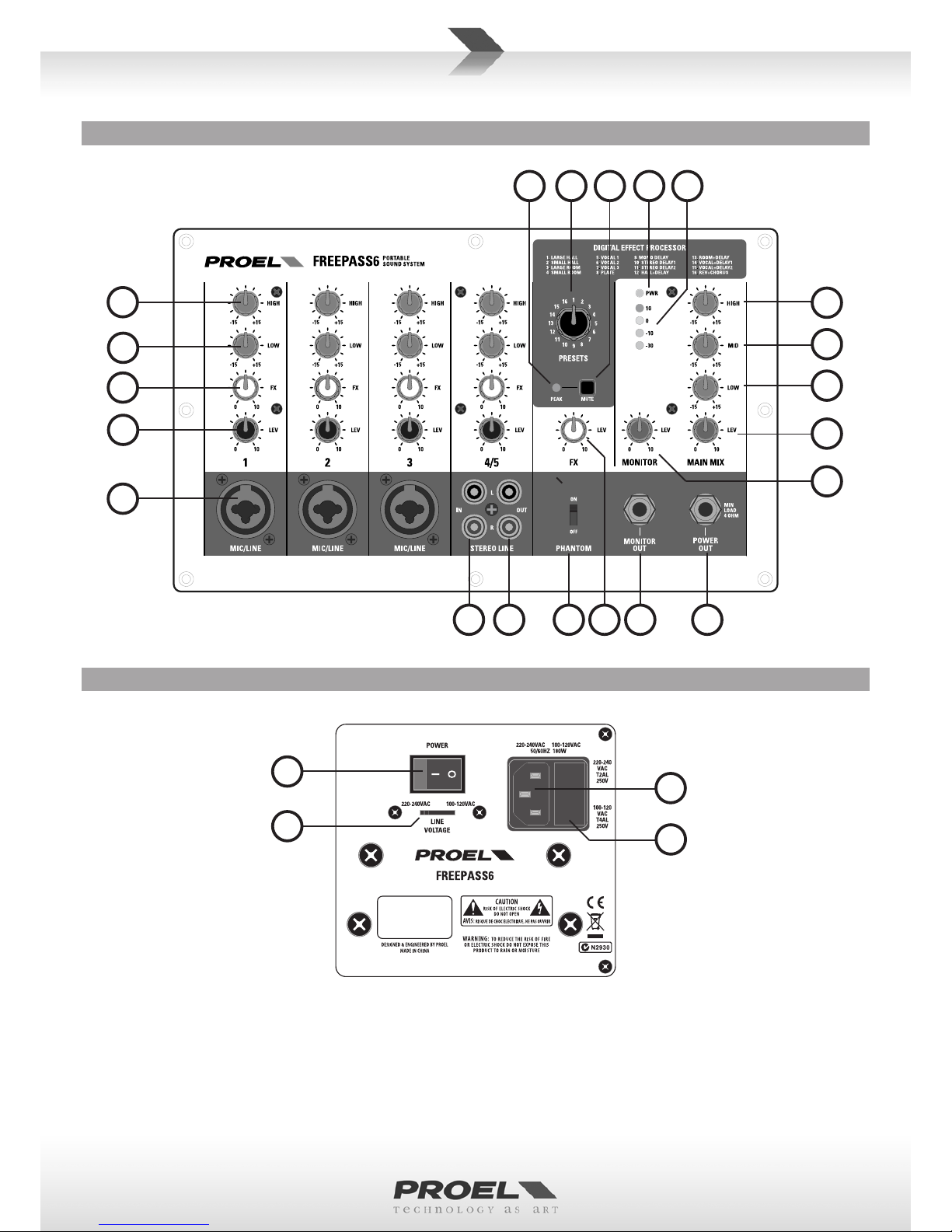
CONTROL PANEL (FIG.1). ....................5
REAR PANEL (FIG.2) . .......................5
CONNECTIONS (FIG.3) . .....................6
CONFIGURATION EXAMPLE (FIG.4) . ...........6
ENGLISH LANGUAGE. .......................7
SAFETY AND PRECAUTIONS . .................7
IN CASE OF FAULT. .........................7
CE CONFORMITY. ..........................7
PACKAGING, SHIPPING AND COMPLAINT . ......7
WARRANTY AND PRODUCTS RETURN . .........7
INSTALLATION AND DISCLAIMER . .............7
POWER SUPPLY AND MAINTENANCE . .........7
GENERAL INFORMATION . ...................8
OPERATING INSTRUCTIONS (FIG. 1 / 2 / 3 / 4) . ..8
INDICE
SPECIFICHE TECNICHE ......................3
DIMENSIONI . .............................4
PANNELLO DI CONTROLLO (FIG.1) . ............5
PANNELLO POSTERIORE (FIG.2) . ..............5
CONNESSIONI (FIG.3) . ......................6
ESEMPIO CONFIGURAZIONE (FIG.4) . ..........6
LINGUA ITALIANA . ........................11
AVVERTENZE PER LA SICUREZZA . ............11
IN CASO DI GUASTO . ......................11
CONFORMITÀ CE. .........................11
IMBALLAGGIO, TRASPORTO E RECLAMI . ......11
GARANZIE E RESI . ........................11
INSTALLAZIONE E LIMITAZIONI D’USO. ........11
ALIMENTAZIONE E MANUTENZIONE . .........11
INFORMAZIONI GENERALI . .................12
ISTRUZIONI OPERATIVE (FIG. 1 / 2 / 3 / 4). . . . . . 12
MIXER SECTION SEZIONE MIXER
MONO channels (3) MIC/LINE input (XLR/JACK combo) Canali MONO (3) ingresso MIC/LINE (XLR/JACK combo)
STEREO channels (1) LINE input (2 x RCA) Canali STEREO (1) ingresso LINE (2 x RCA)
Input Channel EQ HIGH: +/-15dB 10 kHz, LOW: +/- 15dB 100 Hz Equalizzatori Ingressi ALTI: +/-15dB 10 kHz, BASSI: +/- 15dB 100 Hz
Phantom power + 15 V (CH 1-3) Alimentazione Phantom + 15 V (CH 1-3)
Eect processor 24 bit digital - 16 Preset Processore eeo 24 bit digitale - 16 Preset
Eect presets HALL, ROOM, VOCAL and PLATE reverbs,
DELAY, REV + DELAY, REV +CHORUS
Impostazioni eeo riverberi HALL, ROOM, VOCAL e PLATE,
DELAY, REV + DELAY, REV +CHORUS
MONITOR out 1 x 3/4" jack Uscita MONITOR 2 x JACK 6,3mm
STEREO LINE out 2 x RCA Uscita STEREO LINE 2 x RCA
Main EQ 3-band EQ (HIGH, MID & LOW) EQ Main EQ 3-bande (HIGH, MID & LOW)
POWER OUT 1 x 3/4" jack (speaker 4 ohm min) Uscita SPEAKER 1 x jack 6,3mm (altoparlante min 4 ohm)
Metering 4-LED VU-METER Misurazione Livello 4-LED VU-METER
AMPLIFIER SECTION SEZIONE AMPLIFICATORE
Connuous Power 75 W @ 4 ohm (1 KHz, 1% THD) Potenza Connua 75 W @ 4 ohm (1 KHz, 1% THD)
Maximum Power 150 W @ 4 ohm (1 KHz, 1% THD) Potenza massima 150 W @ 4 ohm (1 KHz, 1% THD)
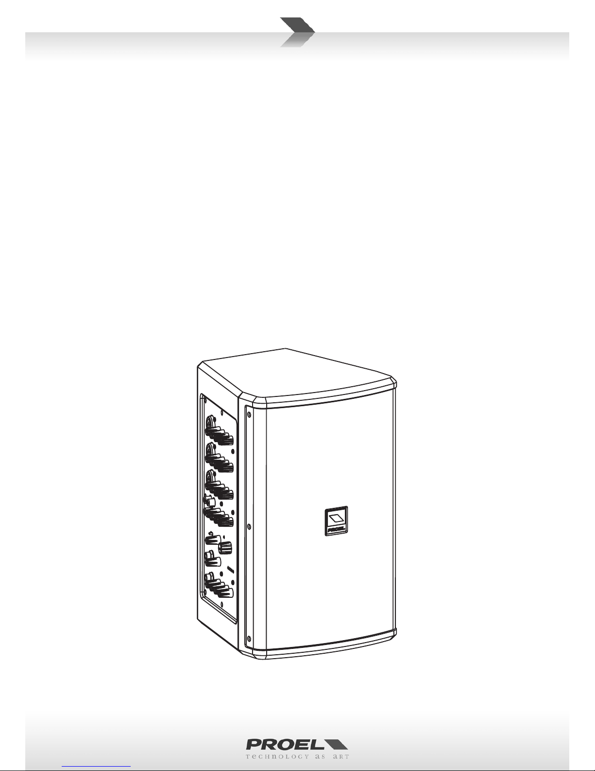
LOUDSPEAKER SECTION SEZIONE ALTOPARLANTE
System 2 Way - Vented Box Sistema 2 Vie - Bass Reex
Low Frequency Device 6.5” woofer with 1" VC Altoparlante Bassi 6.5” woofer con 1" VC
High Frequency Device 1” neodymium tweeter Altoparlante Al 1” neodymium tweeter
Angular Coverage 90° H x 60° V Copertura Angolare 90° O x 60° V
Impedance 4 ohm Impedenza nominale 4 ohm
Frequency Response 75 Hz - 20 kHz (-6 dB) Risposta in Frequenza 75 Hz - 20 kHz (-6 dB)
Max SPL 110 dB SPL massima 110 dB
Construcon MDF with black anscratch paint, metal grille Costruzione MDF colore nero angrao, griglia metallica
Pole holder 1 oponally aachable at boom or at side Flangia per supporto 1 opzionale collegabile soo o al anco
GENERAL SPECIFICATION SPECIFICHE GENERALI
Power Supply 230 V~ / 120 V~ (switchable) 50/60 Hz Alimentazione 230 V~ / 120 V~ (commutabile) 50/60 Hz
Consumpon 180 W Assorbimento 180 W
Dimensions (W x H x D) 200 x 320 x 220 mm Dimensioni (L x A x P) 200 x 320 x 220 mm
Weight 6.2 kg (13.7 lb) Peso 6.2 kg
TECHNICAL SPECIFICATIONS SPECIFICHE TECNICHE

4
DIMENSIONS DIMENSIONI
32.0 cm
12.6"
20.0 cm
7.87"
22.0 cm
8.66"
M4 Pole holder
fixing point
LT6 Pole adapter (supplied)

5
CONTROL PANEL (FIG.1) PANNELLO DI CONTROLLO (FIG.1)
1
2
3
4
5
REAR PANEL (FIG.2) PANNELLO POSTERIORE (FIG.2)
22 1417 1820
8
10
9
11
15
671213 1619
23
24
21
25

6
LINE IN
Jack (bilanciato)
LINE IN
Jack (balanced)
sleeve - ground
p - hot
ring - cold
MIC INPUT
XLR bilanciato maschio
MIC INPUT
Balanced male XLR
ground
hot
cold
INPUT B, REC OUTPUT
RCA (sbilanciato)
INPUT B, REC OUTPUT
RCA (unbalanced)
ground
hot
LINE IN, PRE OUT
Jack (sbilanciato)
LINE IN, PRE OUT
Jack (unbalanced)
USCITA ALTOPARLANTISPEAKER OUTPUT
note: use the power cable supplied nota: usare il cavo di potenza fornito
ground
p - hot
*nota: conneere insieme 2 e 3
per cavi da bilanciato a sbilanciato
*note: connect both 2 and 3 to
make cable from balanced to unbalanced
CONNECTIONS (FIG.3) CONNESSIONI (FIG.3)
CONFIGURATION EXAMPLE (FIG.4) ESEMPIO CONFIGURAZIONE (FIG.4)
KEYBOARD
GUITAR
VOCAL MIC
PERSONAL
COMPUTER
LT6A or other
acve speaker
LT6P or other
passive speaker
(75W applicable power and
4 ohm minimum impedance)

7
ENGLISH LANGUAGE
SAFETY AND PRECAUTIONS
• CAUTION: before using this product read carefully the following safety instrucons. Take a look of this manual enrely and preserve it for
future reference.
When using any electric product, basic precauons should always be taken, including the following:
– To reduce the risk, close supervision is necessary when the product is used near children.
– Protect the apparatus from atmospheric agents and keep it away from water, rain and high humidity places.
– This product should be site away from heat sources such as radiators, lamps and any other device that generate heat.
– Care should be taken so that objects and liquids do not go inside the product.
– The product should be connected to a power supply mains line only of the type described on the operang instrucons or as marked on the
product. Connect the apparatus to a power supply using only power cord included making always sure it is in good condions.
– WARNING: The mains plug is used as disconnect device, the disconnect device shall remain readily operable.
– Power supply cord should be unplugged from the outlet during strong thunderstorm or when le unused for a long period of me.
– Do not place objects on the product’s power cord or place it in a posion where anyone could trip over, walk on or roll anything over it. Do not
allow the product to rest on or to be installed over power cords of any type. Improper installaons of this type create the possibility of re hazard
and/or personal injury.
IN CASE OF FAULT
• In case of fault or maintenance this product should be inspected only by qualied service personnel when:
– There is a aw either in the connecons or in the supplied connecng cables.
– Liquids have spilled inside the product.
– The product has fallen and been damaged.
– The product does not appear to operate normally or exhibits a marked change in performance.
– The product has been lost liquids or gases or the enclosure is damaged.
• Do not operate on the product, it has no user-serviceable parts inside, refer servicing to an authorized maintenance centre.
CE CONFORMITY
• Proel products comply with direcve 2004/108/EC (EMC), as stated in EN 55013 standard and with direcve 2006/95/CE (LVD), as stated in EN
60065 standard.
• Under the EM disturbance, the rao of signal-noise will be changed above 10dB.
PACKAGING, SHIPPING AND COMPLAINT
• This unit package has been submied to ISTA 1A integrity tests. We suggest you control the unit condions immediately aer unpacking it.
• If any damage is found, immediately advise the dealer. Keep all unit packaging parts to allow inspecon.
• Proel is not responsible for any damage that occurs during shipment.
• Products are sold “delivered ex warehouse” and shipment is at charge and risk of the buyer.
• Possible damages to unit should be immediately noed to forwarder. Each complaint for package tampered with should be done within eight
days from product receipt.
WARRANTY AND PRODUCTS RETURN
• Proel products have operang warranty and comply their specicaons, as stated by manufacturer.
• Proel warrants all materials, workmanship and proper operaon of this product for a period of two years from the original date of purchase. If
any defects are found in the materials or workmanship or if the product fails to funcon properly during the applicable warranty period, the owner
should inform about these defects the dealer or the distributor, providing receipt or invoice of date of purchase and defect detailed descripon.
This warranty does not extend to damage resulng from improper installaon, misuse, neglect or abuse. Proel S.p.A. will verify damage on returned
units, and when the unit has been properly used and warranty is sll valid, then the unit will be replaced or repaired. Proel S.p.A. is not responsible
for any "direct damage" or "indirect damage" caused by product defecveness.
INSTALLATION AND DISCLAIMER
• Proel products have been expressly designed for audio applicaon, with signals in audio range (20Hz to 20kHz). Proel has no liability for damages
caused in case of lack of maintenance, modicaons, improper use or improper installaon non-applying safety instrucons.
• Proel S.p.A. reserves the right to change these specicaons at any me without noce.
• Proel S.p.A. declines any liability for damages to objects or persons caused by lacks of maintenance, improper use, installaon not performed
with safety precauons and at the state of the art.
POWER SUPPLY AND MAINTENANCE
• Clean only with dry cloth.
• Before connecng the product to the mains outlet make certain that the mains line voltage matches that shown on the rear of the product, a
tolerance of up to ±10% is acceptable.

8
GENERAL INFORMATION
Thank you for having chosen a PROEL product.
FREEPASS6 is a combo sound system including a speaker, an amplier and a 5-input mixer in an ultra-compact and
portable package. The 2-way speaker system includes a 1” neodymium tweeter and a 6.5” woofer, able to provide an
extended and detailed frequency response. The built-in amplier delivers to the speakers 75W of connuous power. In
addion, it can power an external speaker with another 75W thru the POWER OUT connector.
The system includes a high-quality 5-input mixer featuring 2-band CHANNEL EQ, 3-band MAIN MIX EQ, MONITOR output
and a sophiscated DIGITAL EFFECT with 16 presets.
FREEPASS6 is hosted in a compact and rugged MDF cabinet nished with a durable an-scratch black paint, which
provides maximum portability and road-proof operaon. Two M4 threaded inserts on the boom and on the side of
the cabinet allow the included metal adapter to be used for installing the system on a standard speaker stand, both in
vercal and horizontal posion.
FREEPASS6 is a cost-eecve, ultra-compact, all-in-one system for mobile musicians, vocal P.A. and indoor sporng,
religious or business events. The 5 inputs available in the built-in mixer allows a variety of signals to be connected,
while the possibility to double the power connecng a second speaker allows the system to be used also in outdoor
applicaon where a higher SPL is required.
OPERATING INSTRUCTIONS (FIG. 1 / 2 / 3 / 4)
1. CH1-3 MIC/LINE Input
This is a female JACK/XLR combo connector, which accepts a balanced microphone XLR input from almost any type of
microphone, or a line JACK input, which accepts a balanced or unbalanced line level input signal from almost any source.
The XLR inputs are wired as follows:
Pin 1 = shield or ground
Pin 2 = + posive or "hot"
Pin 3 = - negave or "cold"
The ¼” (6.3mm) jack inputs are wired as follows:
Tip = + posive or "hot"
Ring = - negave or "cold"
Sleeve = shield or ground
When connecng an unbalanced signal, wire them as follows:
Tip = + posive or "hot"
Sleeve = shield or ground
2. CH1-5 LEVEL control.
Adjusts the level of the channel signal.
3. CH1-5 HIGH tone control
This control boosts or cuts the high frequencies with a "SHELVING" curve shape. Use it to increase or reduce the sound
"clarity" or "brightness".
4. CH1-5 LOW tone control
This control boosts or cuts the low frequencies with a "SHELVING" curve shape. Use it to increase or reduce the sound
"punch".
5. CH1-5 FX level control
This control sends the signal to the internal digital eect processor. This signal is post-fader, or in other words it depends
on the posion of the channel's FADER.
6. CH4-5 STEREO LINE inputs
Use these unbalanced RCA connectors to patch the output of a player, such as an analog tape deck, MP3 player, CD/DVD
player or a Personal Computer.
7. CH1-3 PHANTOM switch
This switch acvates (ON) and deacvates (OFF) the phantom power on MIC Inputs. Most professional condenser
microphones require phantom power, which is a lower DC voltage delivered to the microphone on pin 2 and 3 of the
XLR microphone connector. Dynamic microphones do not require phantom power, however phantom power will not
harm most dynamic microphones should you plug one in while the phantom power is on. Check the manual of your
microphone to nd out for sure whether or not phantom power can damage it.
8. MAIN MIX HIGH tone control
This control gives you up to 12dB boost or cut at 8KHz with a "SHELVING" curve shape. Use it to increase or reduce the
sound "clarity" or "brightness" of the whole mix.

9
9. MAIN MIX MID tone control
This control gives you up to 12 dB boost or cut at 2.5 KHz with a "PEAKING" curve shape. Use it to add or reduce the
sound "presence" of the whole mix.
10. MAIN MIX LOW tone control
This control gives you up to 12dB boost or cut at 100Hz with a "SHELVING" curve shape. Use it to increase or reduce the
sound "punch" of the whole mix.
11. MAIN MIX level control
It controls the output level of the built-in speaker, of the STEREO LINE output and of the POWER OUT. It controls also
the level of the signal sent to the MONITOR OUTPUT just before its level control.
12. POWER OUT (75W auxiliary output)
This is a jack connector sending the amplied signal to an external passive speaker. Use always power cables to connect
the speaker and note that the minimum acceptable impedance is 4 ohm.
The JACK power output is wired as follows:
Tip = + posive speaker terminal
Sleeve = - negave speaker terminal
13. STEREO LINE outputs
These are RCA connectors sending the MAIN MIX signal to a line level equipment, which could be a recorder or another
audio system. Please note that the level depends on the MAIN MIX control.
14. LEVEL METER
This meter shows the level of the signal sent to the outputs. To avoid excessive distoron, try to avoid the last RED "10"
LED to be connuously on.
15. MONITOR level control
It controls the signal level of the MONITOR OUT. This level depends from the MAIN MIX level.
16. MONITOR OUT
This is a jack connector sending the signal to a line level equipment, which could be a recorder or another audio system.
Each jack output is wired as follows:
Tip = + posive or "hot"
Sleeve = shield or ground
17. PEAK detector
This LED shows 2 condions:
• always lighted = the eect is MUTED.
• ashing = too high input level, near to the overload of the eect input stage. In this case, reduce
the level of the FX sends. The PEAK LED ashes when the eect input signal is near to the A/D saturaon point of the
internal eect processor.
18. MUTE buon
Engage this switch if you want to mute the internal eect.
19. FX level control
It adjusts the level of the internal eect signal sent to the MAIN MIX.
20. PRESETS Selector
Rotate this detented switch to select the preset eect you want to use.
Preset descripons:
1. LARGE HALL - This type of reverb simulates the ambience of a grand concert hall. Dense, smooth reverb with long
tail, long pre delay and some early reecons. Works well with vocals, electric and acousc guitars, strings.
2. SMALL HALL - This type of reverb simulates the ambience of a grand concert hall. Dense, smooth reverb with short
tail, normal pre delay and increased early reecons. Works well with vocals, guitars, woodwinds.
3. LARGE ROOM - This type of reverb reproduces the more inmate ambience of natural room acouscs. Feature
very fast and scaered early reecons, long pre delay. Works well with vocals, woodwinds, strings.
4. SMALL ROOM - This type of reverb reproduces the more inmate ambience of natural room acouscs. Feature
very fast and scaered early reecons, short pre delay. Works well with vocals, ngered guitars, drums.
5. VOCAL 1 - Amazing reverb designed for vocals with a long tail.
6. VOCAL 2 - Amazing reverb designed for vocals with a dense tail.
7. VOCAL 3 - Amazing reverb designed for vocals with a short tail.
8. PLATE - This is a simulaon of metal plate reverb, as used on classic recordings from the '70s and '80s.
9. MONO DELAY - Typical mono delay.
10. STEREO DELAY 1 - Echo eect characterized with a short me.

10
11. STEREO DELAY 2 - Echo e ect characterized with a long me.
12. HALL+DELAY - Combina on of two of the previous presets.
13. ROOM+DELAY - Combina on of two of the previous presets.
14. VOCAL+DELAY 1 - Combina on of two of the previous presets, reverb with short tail and a long delay.
15. VOCAL+DELAY 2 - Combina on of two of the previous presets, reverb with a long tail and a mono delay.
16. REV+CHORUS - Typical vocal reverb and chorus e ect combined together, useful to simulate more instruments
playing together, works well on vocals, guitars, strings, woodwinds.
21. POWER switch
Switch this one on and the unit has power. Make sure that all MAIN knobs are turned all the way down when powering
up or down.
22. PWR indicator
Indicates when the unit is switched on.
23. AC~ SOCKET
Here’s where you plug in your mains supply cord. You should always use the mains cord supplied with the device. Be
sure that your device is turned o before you plug the mains supply cord into an electrical outlet.
24. FUSE holder
Here is where the mains protec on fuse is placed.
REPLACE THE PROTECTION FUSE ONLY WITH SAME TYPE AS SHOWN ON THE PRODUCT.
IF AFTER THE SUBSTITUTION, THE FUSE INTERRUPTS AGAIN THE APPARATUS WORKING, DO NOT TRY AGAIN
THEN CONTACT THE PROEL SERVICE CENTER.
25. LINE VOLTAGE selector
This switch sets the AC voltage line of your country (usually it is set by factory and isn't necessary to change it). The 115V
se ng is for mains line in the range of 105-120V~ and 230V se ng is for mains line in the range of 210-240V~.
WARNING: an incorrect se ng of AC LINE VOLTAGE could damage seriously the internal electronics!

11
LINGUA ITALIANA
AVVERTENZE PER LA SICUREZZA
• ATTENZIONE: Durante le fasi di uso o manutenzione, devono essere prese alcune precauzioni onde evitare danneggiamen alle struure
meccaniche ed eleroniche del prodoo.
Prima di ulizzare il prodoo, si prega di leggere aentamente le seguen istruzioni per la sicurezza. Prendere visione del manuale d’uso e
conservarlo per successive consultazioni:
– In presenza di bambini, controllare che il prodoo non rappresen un pericolo.
– Posizionare l’apparecchio al riparo dagli agen atmosferici e a distanza di sicurezza dall’acqua, dalla pioggia e dai luoghi ad alto grado di
umidità.
– Collocare o posizionare il prodoo lontano da fon di calore quali radiatori, griglie di riscaldamento e ogni altro disposivo che produca
calore.
– Evitare che qualsiasi oggeo o sostanza liquida entri all’interno del prodoo.
– Il prodoo deve essere connesso esclusivamente alla rete elerica delle caraerische descrie nel manuale d’uso o scrie sul prodoo,
usando esclusivamente il cavo rete in dotazione e controllando sempre che sia in buono stato, in parcolare la spina e il punto in cui il cavo esce
dal prodoo.
– ATTENZIONE: Se il cavo rete viene scollegato dall'apparecchio per spegnerlo, il cavo rete rimarrà operavo in quanto la sua spina è ancora
collegata alla rete elerica.
– Disconneere il prodoo dalla rete elerica durante for temporali o se non viene usato per un lungo periodo di tempo.
– Non disporre ogge sul cavo di alimentazione, non disporre i cavi di alimentazione e segnale in modo che qualcuno possa incianparci. Altresì
non disporre l’apparecchio sui cavi di altri appara. Installazioni inappropriate di questo po possono creare la possibilità di rischio di incendio
e/o danni alle persone.
IN CASO DI GUASTO
• In caso di guasto o manutenzione questo prodoo deve essere ispezionato da personale qualicato quando:
– Ci sono dife sulle connessioni o sui cavi di collegamento in dotazione.
– Sostanze liquide sono penetrate all’interno del prodoo.
– Il prodoo è caduto e si è danneggiato.
– Il prodoo non funziona normalmente esibendo una marcato cambio di prestazioni.
– Il prodoo perde sostanze liquide o gassose o ha l’involucro danneggiato.
• Non intervenire sul prodoo. Rivolgersi a un centro di assistenza autorizzato Proel.
CONFORMITÀ CE
• I Prodo Proel sono conformi alla direva 2004/108/EC (EMC), secondo lo standard EN 55013 ed alla direva 2006/95/CE (LVD), secondo lo
standard EN 60065.
• Se sooposto a disturbi EM, il rapporto segnale-rumore può essere superiore a 10dB.
IMBALLAGGIO, TRASPORTO E RECLAMI
• L’imballo è stato sooposto a test di integrità secondo la procedura ISTA 1A. Si raccomanda di controllare il prodoo subito dopo l’apertura
dell’imballo.
• Se vengono riscontra danni informare immediatamente il rivenditore. Conservare quindi l’imballo completo per permeerne l’ispezione.
• Proel declina ogni responsabilità per danni causa dal trasporto.
• Le merci sono vendute “franco nostra sede” e viaggiano sempre a rischio e pericolo del distributore.
• Eventuali avarie e danni dovranno essere contesta al veore. Ogni reclamo per imballi manomessi dovrà essere inoltrato entro 8 giorni dal
ricevimento.
GARANZIE E RESI
• I Prodo Proel sono provvis della garanzia di funzionamento e di conformità alle proprie speciche, come dichiarate dal costruore.
• La garanzia di funzionamento è di 24 mesi dopo la data di acquisto. I dife rileva entro il periodo di garanzia sui prodo vendu, aribuibili a
materiali difeosi o dife di costruzione, devono essere tempesvamente segnala al proprio rivenditore o distributore, allegando evidenza scria
della data di acquisto e descrizione del po di difeo riscontrato. Sono esclusi dalla garanzia dife causa da uso improprio o manomissione. Proel
SpA constata tramite verica sui resi la difeosità dichiarata, correlata all’appropriato ulizzo, e l’eeva validità della garanzia; provvede quindi
alla sostuzione o riparazione dei prodo, declinando tuavia ogni obbligo di risarcimento per danni dire o indire eventualmente derivan
dalla difeosità.
INSTALLAZIONE E LIMITAZIONI D’USO
• I Prodo Proel sono desna esclusivamente ad un ulizzo specico di po sonoro: segnali di ingresso di po audio (20Hz-20kHz). Proel declina
ogni responsabilità per danni a terzi causa da mancata manutenzione, manomissioni, uso improprio o installazione non eseguita secondo le
norme di sicurezza.
• La Proel S.p.a. si riserva di modicare il prodoo e le sue speciche senza preavviso.
• Proel declina ogni responsabilità per danni a terzi causa da mancata manutenzione, manomissioni, uso improprio o installazione non eseguita
secondo le norme di sicurezza e a regola d'arte.
ALIMENTAZIONE E MANUTENZIONE
• Pulire il prodoo unicamente con un panno asciuo.
• Prima di collegare l'apparecchio alla presa di corrente, accertatevi che la tensione di rete corrisponda a quella indicata sul retro dell’apparato, è
consento un margine del ±10% rispeo al valore nominale.

12
INFORMAZIONI GENERALI
Grazie per aver scelto un prodoo PROEL.
FREEPASS6 è un sistema audio combinato formato da un diusore, un amplicatore ed un mixer da 5 canali in un
formato ultra compao e portale. Il diusore a due vie ulizza un tweeter al neodimio da 1” ed un woofer da 6.5”, in
grado di fornire una risposta in frequenza estesa e deagliata.
L’amplicatore incorporato eroga agli altoparlan 75 W di potenza connua e, grazie ad un conneore POWER OUT, è
in grado di alimentare anche un secondo diusore. Il sistema include un mixer a 5 canali di elevata qualità, con EQ di
canale a 2 bande, EQ per il MAIN MIX a 3 bande, uscita MONITOR e un soscato EFFETTO DIGITALE a 16 presets.
FREEPASS6 è alloggiato in un cabinet in MDF robusto e compao, rinito con una resistente vernice an-gra o, che
assicura la massima portabilità e protezione per ogni po di ulizzo. Due inser lea M4 sul fondo e su un anco del
cabinet consentono l’applicazione di un adaatore metallico fornito di serie per l’installazione del sistema su supporto
standard per diusori, in posizione sia vercale che orizzontale.
FREEPASS6 è un sistema di completo ultra-compao ed estremamente conveniente per musicis live, diusione vocale
ed even al chiuso di po religioso, sporvo o commerciale. I 5 ingressi disponibili nel mixer incorporato consentono di
collegare una grande varietà di segnali, mentre la possibilità di raddoppiare la potenza collegando un secondo diusore
rende possibile ulizzare il sistema anche in applicazione all’aperto in cui è richiesta una maggiore pressione sonora.
ISTRUZIONI OPERATIVE (FIG. 1 / 2 / 3 / 4)
1. CH1-3 MIC/LINE (ingresso microfono/linea)
È un conneore femmina XLR/JACK combinato, in grado di acceare un segnale microfonico bilanciato XLR da ogni po
di microfono, o un ingresso JACK linea, in grado di acceare un segnale a livello linea bilanciato o sbilanciato da ogni
po di sorgente.
L'ingresso XLR ha i seguen terminali:
Pin 1 = schermo o massa
Pin 2 = + posivo o "caldo"
Pin 3 = - negavo o "freddo"
L'ingresso JACK femmina da ¼” (6.3mm) ha i seguen terminali:
Tip (punta) = + posivo o "caldo"
Ring (anello) = - negavo o "freddo"
Sleeve (manicoo) = schermo o massa
Quando si collega un segnale sbilanciato, le terminazioni sono le seguen:
Tip (punta) = + posivo o "caldo"
Sleeve (manicoo) = schermo o massa
2. CH1-5 CHANNEL LEVEL (controllo di livello canale).
Regola il livello del segnale del canale corrispondente.
3. CH1-5 HIGH (controllo di toni al)
Questo controllo esalta o aenua le alte frequenze con una curva po "SHELVING". Usarlo per aumentare o ridurre la
"chiarezza" o "brillantezza" del suono.
4. CH1-5 LOW (controllo di toni bassi)
Questo controllo esalta o aenua le basse frequenze con una curva po "SHELVING". Usarlo per aumentare o ridurre
il "vigore" del suono.
5. CH1-5 FX (controllo livello eeo)
Questo controllo invia il segnale all'eeo interno (digital eect processor). Questo segnale è post-fader, o in altre parole
esso dipende dalla posizione del controllo di livello del canale.
6. CH4-5 STEREO LINE (ingresso linea stereo)
Usare ques ingressi sbilancia con conneori RCA per collegare l'uscita di una sorgente linea quale un registratore
analogico, un leore MP3, un leore CD/DVD, l'uscita audio di un computer.
7. CH1-3 PHANTOM (interruore alimentazione phantom)
Questo interruore ava e disava l'alimentazione phantom negli ingressi microfonici MIC. La maggior parte dei
microfoni professionali a condensatore richiedono l'alimentazione phantom, la quale è una bassa tensione connua DC
portata al microfono sui terminali 2 e 3 del conneore XLR. I microfoni dinamici non richiedono l'alimentazione phantom,
tuavia l'alimentazione phantom non dovrebbe arrecare alcun danno ai microfoni dinamici se inseri quando accesa.
Controllare il manuale del microfono per assicurarsi se l'alimentazione phantom possa danneggiarlo.
8. EQ MAIN HIGH (toni al MAIN)
Questo controllo permee di guadagnare o aenuare no a 12dB a 8KHz con una curva di po "SHELVING". Da usarsi
per aumentare o ridurre la "chiarezza" o "brillanza" del suono.

13
9. EQ MAIN MID (toni medi MAIN)
Questo controllo permee di guadagnare o aenuare no a 12 dB a 2.5 KHz con una curva po "PEAKING". Da usarsi
per aumentare o ridurre la "presenza" del suono.
10. EQ MAIN LOW (toni bassi MAIN)
Questo controllo permee di guadagnare o aenuare no a 12dB a 100Hz con una curva di po "SHELVING". Da usarsi
per aumentare o ridurre il "vigore" del suono.
11. MAIN MIX (controllo livello MAIN MIX)
Il MAIN MIX controlla il livello di uscita dell’altoparlante incluso, delle uscite STEREO LINE e dell’uscita POWER OUT.
Controlla anche il livello dell’uscita MONITOR OUT prima del suo proprio controllo.
12. POWER OUT (uscita di potenza ausiliaria 75W)
Questo jack è in grado di inviare il segale amplicato ad un'altro altoparlante. Usare sempre cavi di potenza per collegare
gli altoparlan e notare che l’impedenza minima acceata è di 4 ohm.
I JACK delle uscite di potenza sono termina come segue:
Tip (punta) = + terminale posivo altoparlante
Sleeve (manico) = - terminale negavo altoparlante
13. STEREO LINE (uscita registratore esterno)
Ques sono conneori RCA che inviano il segnale del MAIN MIX ad un apparecchio esterno a livello linea, il quale può
essere un registratore o un'altro sistema audio. Il livello è dipendente dal controllo MAIN MIX.
14. LEVEL METER (indicatore di livello)
L'indicatore di livello mostra il livello del segnale inviato alle uscite. Per evitare una eccessiva distorsione, cercare di
evitare l'accensione pressoché costante dell'ulmo LED rosso "10".
15. MONITOR LEVEL (controllo di livello MONITOR)
Il MONITOR LEVEL controlla il livello dell'uscita MONITOR. Questo livello è dipendente dal livello MAIN MIX.
16. MONITOR OUT (uscita linea monitor)
Questo conneore jack invia all'esterno un segnale linea ad un'altro apparato che può essere un registratore o un'altro
sistema audio.
Ogni uscita jack è terminata come segue:
Tip (punta) = + posivo o "caldo"
Sleeve (manicoo) = schermo o massa
17. PEAK (rilevatore di picco)
Questo LED mostra 2 condizioni:
• sempre acceso = l'eeo e in MUTE.
• lampeggiante = segnala un livello di ingresso troppo alto, prossimo a sovvracaricare l'ingresso dell'eeo. In questo
caso, ridurre il livello delle mandate FX.
18. MUTE (pulsante per silenziare l'eeo)
Premere questo pulsante se si vuole silenziare l'eeo interno.
19. FX LEVEL (livello eeo)
Regola il livello del segnale dell'eeo interno inviato al MAIN MIX.
20. PRESETS (seleore eeo)
Ruotare questo seleore per scegliere l'eeo desiderato.
Descrizione dei PRESET:
1. LARGE HALL - Questo po di riverbero simula l'ambiente di una grande sala da concerto. Denso e armonioso
riverbero con una coda lunga, lungo pre delay e poche prime riessioni. Adao a voci, chitarre eleriche e acusche,
archi.
2. SMALL HALL - Questo po di riverbero simula l'ambiente di una grande sala da concerto. Denso e armonioso
riverbero con una coda corta, normale pre delay e tante prime riessioni. Adao a voci, chitarre, a.
3. LARGE ROOM - Questo po di riverbero riproduce un più inmo ambiente acusco di una stanza. Caraerizzato
da veloci e sparpagliate prime riessioni, lungo pre delay. Adao a voci, a, archi.
4. SMALL ROOM - Questo po di riverbero riproduce un più inmo ambiente acusco di una stanza. Caraerizzato
da veloci e sparpagliate prime riessioni, corto pre delay. Adao a voci, chitarre pizzicate, percussioni.
5. VOCAL 1 - Riverbero modellato per voci con coda lunga.
6. VOCAL 2 - Riverbero modellato per voci con coda densa.
7. VOCAL 3 - Riverbero modellato per voci con coda corta.
8. PLATE - Questa è una simulazione del riverbero "plate", usato nelle classiche registrazioni degli anni '70 e '80.
9. MONO DELAY - Tipico eco mono.

14
10. STEREO DELAY 1 - E e o eco, cara erizzato da un tempo di ripe zione corto.
11. STEREO DELAY 2 - E e o eco, cara erizzato da un tempo di ripe zione lungo.
12. HALL+DELAY - Combinazione di due dei preceden e e .
13. ROOM+DELAY - Combinazione di due dei preceden e e .
14. VOCAL+DELAY 1 - Combinazione di due dei preceden e e , riverbero con una coda corta e un delay lungo.
15. VOCAL+DELAY 2 - Combinazione di due dei preceden e e , riverbero con una coda lunga e un delay corto.
16. REV+CHORUS - Tipico riverbero per voce e e e o chorus combina assieme, u le per simulare più strumen
suonan assieme, opera bene su voci, chitarre, archi, a .
21. POWER (interru ore accensione)
Commutando su ON questo interru ore l'apparato è alimentato. Assicurarsi che tu e le manopole MAIN siano al minimo
quando si accende o spegne l'apparato.
22. PWR (indicatore di accensione)
Indica quando l'apparato è acceso.
23. AC~ (presa di rete)
Inserire in questa presa il cavo di alimentazione di rete, u lizzando esclusivamente il cavo in dotazione. Accertarsi che
l'altoparlante sia spento prima di collegarlo alla rete.
24. FUSE (portafusibile)
In questo vano è inserito il fusibile di protezione principale di rete.
RIMPIAZZARE IL FUSIBILE DI PROTEZIONE ESCLUSIVAMENTE CON UN FUSIBILE CON LE MEDESIME
CARATTERISTICHE RIPORTATE SUL PRODOTTO.
SE DOPO LA SOSTITUZIONE, IL FUSIBILE INTERROMPE NUOVAMENTE IL FUNZIONAMENTO DELL'APPARATO, NON
INSISTERE E CONTATTARE IL SERVIZIO ASSISTENZA PROEL.
25. LINE VOLTAGE (sele ore tensione di rete)
Questo sele ore imposta la tensione di rete della linea ele rica del vostro paese ( picamente è già impostato di fabbrica
e non è necessario cambiarlo). L'impostazione 115V è per le linee ele riche da 105-120V~ e l'impostazione 230V è per
le linee ele riche da 210-240V~.
ATTENZIONE una sbagliata impostazione della linea ele rica AC LINE VOLTAGE può danneggiare seriamente
l'ampli catore interno.

15

REV. 16/14 CODE 96MAN0093
PROEL S.p.A.
(World Headquarter)
Via alla Ruenia 37/43
64027 Sant’Omero (TE) - ITALY
Tel: +39 0861 81241
Fax: +39 0861 887862
www.proel.com
Table of contents
Languages:
Other PROEL Speakers manuals

PROEL
PROEL CS06EN User manual

PROEL
PROEL MO3T User manual

PROEL
PROEL A31T User manual

PROEL
PROEL NEOS SERIES User manual

PROEL
PROEL V8PLUS User manual

PROEL
PROEL WEDGE WD10A User manual

PROEL
PROEL HSPL40 User manual

PROEL
PROEL NET10A User manual

PROEL
PROEL CS5TALEN User manual

PROEL
PROEL FLASH15HDA User manual

PROEL
PROEL NEXT User manual

PROEL
PROEL NEOS152AXS User manual

PROEL
PROEL FREE8LT User manual

PROEL
PROEL HSPL30 User manual

PROEL
PROEL FLASH15A V2 User manual

PROEL
PROEL NEOS15PX User manual

PROEL
PROEL NEOS15AXS User manual

PROEL
PROEL XE55CTX Operating manual

PROEL
PROEL V10A User manual

PROEL
PROEL FLASH8XD User manual