PROEL V10A User manual

V series
V10A - V12A - V15A
acve loudspeakers
USER MANUAL
MANUALE D'USO
BENUTZERHANDBUCH
NOTICE D'UTILISATION
MANUAL DE USO

FCC COMPLIANCE NOTICE
This device complies with part 15 of the FCC rules. Operaon is subject to the following two condions:
(1) This device may not cause harmful interference, and
(2) this device must accept any interference received, including interference that may cause undesired operaon.
CAUTION: Changes or modicaons not expressly approved by the party responsible for compliance could void
the user’s authority to operate the equipment.
NOTE: This equipment has been tested and found to comply with the limits for a Class B digital device, pursuant to
part 15 of the FCC Rules. These limits are designed to provide reasonable protecon against harmful interference in
a residenal installaon. This equipment generates, uses, and can radiate radio frequency energy and, if not installed
and used in accordance with the instrucon manual, may cause harmful interference to radio communicaons.
However, there is no guarantee that interference will not occur in a parcular installaon. If this equipment does
cause harmful interference to radio or television recepon, which can be determined by turning the equipment o
and on, the user is encouraged to try to correct the interference by one or more of the following measures:
• Reorient or relocate the receiving antenna.
• Increase the separaon between the equipment and receiver.
• Connect the equipment into an outlet on a circuit dierent from that to which the receiver is connected.
• Consult the dealer or an experienced radio/TV technician for help.
This marking shown on the product or its literature, indicates that it should not be disposed with other household wastes at the end of
its working life. To prevent possible harm to the environment or human health from uncontrolled waste disposal, please separate this
from other types of wastes and recycle it responsibly to promote the sustainable reuse of material resources. Household users should
contact either the retailer where they purchased this product, or their local government oce, for details of where and how they can
take this item for environmentally safe recycling. Business users should contact their supplier and check the terms and condions of the
purchase contract. This product should not be mixed with other commercial wastes for disposal.
The lightning ash with arrowhead symbol within an equilateral triangle is intended to alert the user to the presence of uninsulated
“dangerous voltage” within the product’s enclosure, that may be of sucient magnitude to constute a risk of electric shock to persons.
The exclamaon point within an equilateral triangle is intended to alert the user to the presence of important operang and maintenance
(servicing) instrucons in the literature accompanying the appliance.
The informaon contained in this publicaon has been carefully prepared and checked. However no responsibility will be taken for any errors. All
rights are reserved and this document cannot be copied, photocopied or reproduced in part or completely without wrien consent being obtained
in advance from PROEL. PROEL reserves the right to make any aesthec, funconal or design modicaon to any of its products without any prior
noce. PROEL assumes no responsibility for the use or applicaon of the products or circuits described herein.
Il marchio riportato sul prodoo o sulla documentazione indica che il prodoo non deve essere smalto con altri riu domesci al
termine del ciclo di vita. Per evitare eventuali danni all’ambiente si invita l’utente a separare questo prodoo da altri pi di riu e di
riciclarlo in maniera responsabile per favorire il riulizzo sostenibile delle risorse materiali. Gli uten domesci sono invita a contaare
il rivenditore presso il quale è stato acquistato il prodoo o l’ucio locale preposto per tue le informazioni relave alla raccolta
dierenziata e al riciclaggio per questo po di prodoo. Gli uten aziendali sono invita a contaare il proprio fornitore e vericare i
termini e le condizioni del contrao di acquisto. Questo prodoo non deve essere smalto unitamente ad altri riu commerciali.
Il simbolo del lampo con freccia in un triangolo equilatero intende avverre l'ulizzatore per la presenza di "tensioni pericolose" non isolate
all'interno dell'involucro del prodoo, che possono avere una intensità suciente a costuire rischio di scossa elerica alle persone.
Il punto esclamavo in un triangolo equilatero intende avverre l'ulizzatore per la presenza di importan istruzioni per l'ulizzo e la
manutenzione nella documentazione che accompagna il prodoo.
Le informazioni contenute in questo documento sono state aentamente redae e controllate. Tuavia non è assunta alcuna responsabilità per
eventuali inesaezze. Tu i diri sono riserva e questo documento non può essere copiato, fotocopiato, riprodoo per intero o in parte senza
previo consenso scrio della PROEL. PROEL si riserva il dirio di apportare senza preavviso cambiamen e modiche esteche, funzionali o di
design a ciascun proprio prodoo. PROEL non assume alcuna responsabilità sull’uso o sull’applicazione dei prodo o dei circui qui descri.

Das Kennzeichen auf dem Gerät oder den beiliegenden Unterlagen zeigt an, dass das Gerät am Ende seiner Lebensdauer nicht im Hausmüll entsorgt werden darf.
Aus Umweltschutzgründen bien wir den Anwender, das Gerät von anderem Müll getrennt zu entsorgen und dem Recycling zuzuführen, damit die Rohstoe
umweltverträglich wiederverwertet werden können. Private Anwender wenden sich dazu bie an den Händler, bei dem sie das Produkt gekau haben, oder an eine
örtliche Behörde, die für Informaonen zur Mülltrennung und zum Recycling dieser Art von Geräten geben kann. Gewerbliche Anwender werden gebeten, sich an
den Zulieferer zu wenden und die Vertragsbedingungen des Kaufvertrags zu überprüfen. Das Gerät darf nicht zusammen mit anderem Gewerbemüll entsorgt werden.
Das Symbol mit einem Pfeilblitz in einem gleichseigen Dreieck warnt den Anwender vor „gefährlicher Spannung“ ohne Isolierung im Gehäuse des Geräts. Diese kann
hoch genug sein, um Stromschlaggefahr zu verursachen.
Das Ausrufezeichen in einem gleichseigen Dreieck weist den Anwender auf wichge Anweisungen zum Gebrauch und zur Instandhaltung des Geräts in den beiligenden
Unterlagen hin.
Die Angaben in diesem Dokument wurden sorgfälg zusammengestellt und kontrolliert. Für mögliche Ungenauigkeiten übernehmen wir dennoch keine Haung. Alle Rechte
vorbehalten. Das Dokument darf ohne vorherige schriliche Genehmigung von PROEL nicht ganz oder in Teilen kopiert oder reproduziert werden. PROEL behält sich das Recht
vor, ohne Vorankündigung Änderungen an der Gestaltung, an den Funkonen oder am Design aller ihrer Produkte vorzunehmen. PROEL haet nicht für den Gebrauch oder die
Verwendung der hier beschriebenen Geräte oder elektrischen Systeme.
La marque reportée sur le produit ou sur la documentaon indique que l'appareil ne doit pas être éliminé avec d'autres déchets domesques au
terme du cycle de sa vie. An d'éviter tout dommage à l'environnement, l'ulisateur est invité à séparer cet appareil des autres types de déchets
et de le recycler de manière responsable pour favoriser la réulisaon durable des ressources matérielles. Les ulisateurs domesques sont invités
à contacter le revendeur où l'appareil a été acheté ou le service local préposé an d'obtenir toutes les informaons relaves au tri sélecf et au
recyclage pour ce type de produit. Les ulisateurs des entreprises sont invités à contacter leur fournisseur et à vérier les termes et les condions
du contrat d'achat. Cet appareil ne doit pas être éliminé avec d'autres déchets commerciaux.
Le symbole d'un éclair avec une èche dans un triangle équilatéral est desné à averr l'ulisateur de la présence de « tensions dangereuses » non
isolées dans le boîer de l'appareil, lesquelles peuvent avoir une intensité susante pour constuer un risque de choc électrique pour les personnes.
Le point d'exclamaon dans un triangle équilatéral est desné à averr l'ulisateur de la présence d'instrucons importantes en vue de l'ulisaon
et de la maintenance de l'appareil dans la documentaon qui l'accompagne.
Les informaons contenues dans ce document ont été rédigées avec aenon et contrôlées. Toutefois, la société PROEL n'assume aucune responsabilité
en cas d'inexactude. Tous les droits sont réservés et ce document ne peut être copié, photocopié, reproduit en ener ou en pare, sans avoir obtenu au
préalable le consentement écrit de la société PROEL. PROEL se réserve le droit d'apporter, sans préavis, des changements et des modicaons esthéques,
fonconnelles ou de design à tous ses produits. PROEL n'assume aucune responsabilité quant à l'ulisaon ou l'applicaon des appareils ou des circuits
décrits dans cee noce.
La marca reproducida en el producto o en la documentación indica que el producto no se debe eliminar con otros desechos doméscos al nal de su
ciclo de vida úl. Para evitar posibles daños al medio ambiente se invita al usuario a separar este producto de otros pos de desechos y reciclarlo de
forma responsable para favorecer el uso sostenible de los recursos materiales. Los usuarios doméscos deben ponerse en contacto con el revendedor
donde han comprado el producto o la ocina local encargada, para conocer todas las informaciones correspondientes a la recogida selecva y al
reciclaje para este po de producto. Se invita a las empresas a ponerse en contacto con su proveedor y controlar los términos y las condiciones del
contrato de compra. Este producto no se debe eliminar junto con otros desechos comerciales.
El símbolo del relámpago con echa en un triángulo equilátero ene la intención de adverr al usuario respecto a la presencia de "tensiones peligrosas"
no aisladas dentro de la envoltura del producto, que pueden tener una intensidad suciente para constuir riesgo de descarga eléctrica a las personas.
El punto exclamavo en un triángulo equilátero ene la intención de adverr al usuario respecto a la presencia de importantes instrucciones para el
uso y el mantenimiento en la documentación que acompaña el producto.
Las informaciones contenidas en este documento se han redactado y controlado atentamente. Sin embargo, el fabricante se exime de toda responsabilidad
por posibles inexactudes. Todos los derechos reservados; por tanto este documento no se puede copiar, fotocopiar, reproducir total o parcialmente sin la
autorización previa escrita por parte de PROEL. PROEL si reserva el derecho de realizar sin previo aviso cambios estécos, funcionales o de diseño a cualquier
producto suyo. PROEL no se asume ninguna responsabilidad por el uso o la aplicación de los productos o de los circuitos que se describen aquí.
PROELPROEL
PROEL

4
INDEX
TECHNICAL SPECIFICATIONS . . . . . . . . . . . . . . . . . 5
FREQUENCY RESPONSE . . . . . . . . . . . . . . . . . . . . . 5
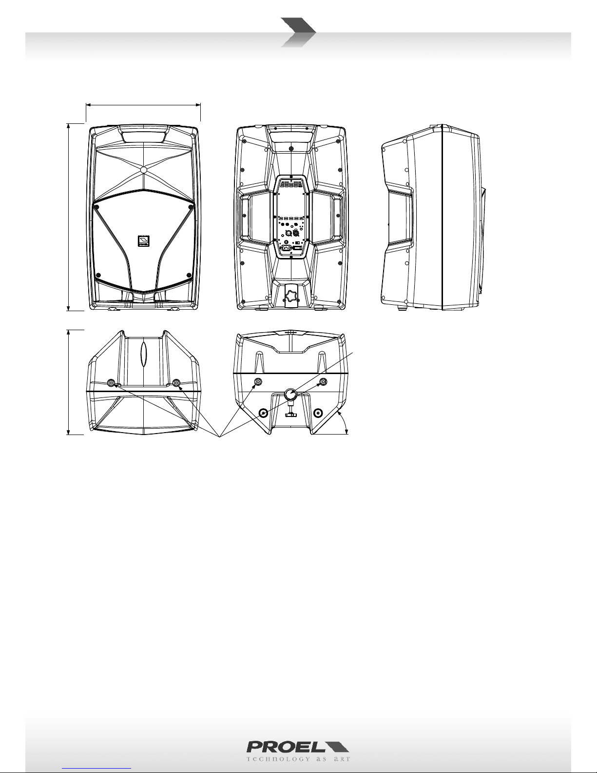
DIMENSIONS AND FLYING POINTS .............6
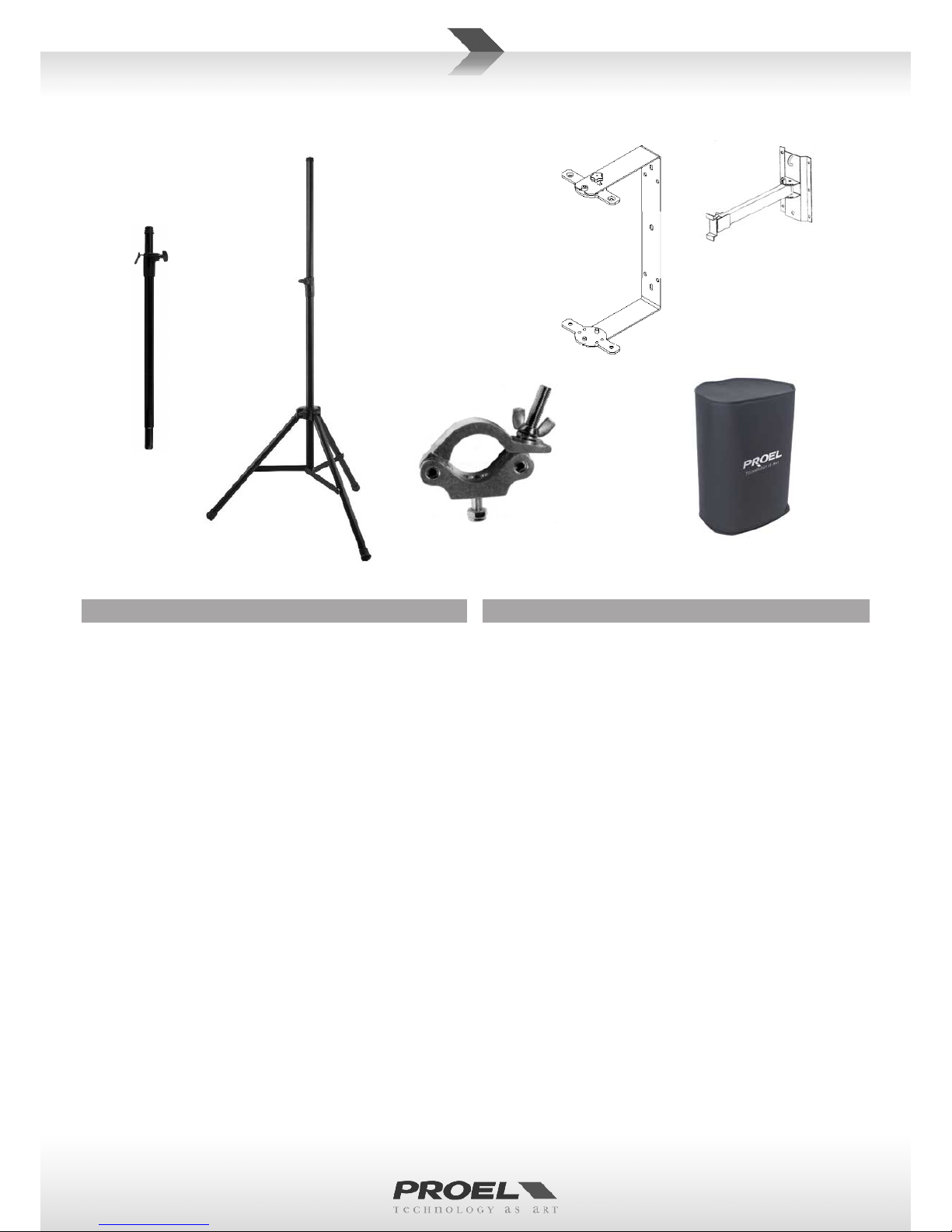
ACCESSORIES .............................8
CONTROL PANEL (FIG.1) .....................9
CONNECTIONS (FIG.2) .....................10
CONFIGURATIONS (FIG.3) . . . . . . . . . . . . . . . . . . 11
SAFETY AND PRECAUTIONS .................12
IN CASE OF FAULT .........................12
TROUBLESHOOTING .......................12
CE CONFORMITY ..........................13
PACKAGING, SHIPPING AND COMPLAINT . . . . . . 13
WARRANTY AND PRODUCTS RETURN . . . . . . . . . 13
INSTALLATION AND DISCLAIMER . . . . . . . . . . . . . 13
POWER SUPPLY AND MAINTENANCE . . . . . . . . . 13
GENERAL INFORMATION . . . . . . . . . . . . . . . . . . . 14
INSTRUCTIONS (FIG. 1 / 2 / 3) . . . . . . . . . . . . . . . 14
INDICE
SPECIFICHE TECNICHE . . . . . . . . . . . . . . . . . . . . . . 5
RISPOSTA IN FREQUENZA . . . . . . . . . . . . . . . . . . . . 5
DIMENSIONI E PUNTI DI SOSPENSIONE. . . . . . . . . 6
ACCESSORI ...............................8
PANNELLO DI CONTROLLO (FIG.1) .............9
CONNESSIONI (FIG.2) ......................10
CONFIGURAZIONI (FIG.3) . . . . . . . . . . . . . . . . . . . 11
AVVERTENZE PER LA SICUREZZA .............16
IN CASO DI GUASTO .......................16
PROBLEMATICHE COMUNI . . . . . . . . . . . . . . . . . . 16
CONFORMITÀ CE ..........................18
IMBALLAGGIO, TRASPORTO E RECLAMI . . . . . . . 17
GARANZIE E RESI .........................17
INSTALLAZIONE E LIMITAZIONI D’USO . . . . . . . . . 17
ALIMENTAZIONE E MANUTENZIONE . . . . . . . . . . 17
INFORMAZIONI GENERALI . . . . . . . . . . . . . . . . . . 18
ISTRUZIONI (FIG. 1 / 2 / 3) . . . . . . . . . . . . . . . . . . 18
INHALT
TECHNISCHE DATEN ........................5
FREQUENZGANG ...........................5
ABMESSUNGEN UND AUFHÄNGEPUNKTE . . . . . . 6
ZUBEHÖR ................................9
REGLER (ABB.1). . . . . . . . . . . . . . . . . . . . . . . . . . . 10
ANSCHLÜSSE (ABB.2) ......................11
KONFIGURATIONEN (ABB.3) . . . . . . . . . . . . . . . . . 12
SICHERHEITSHINWEISE . . . . . . . . . . . . . . . . . . . . . 21
BEI EINEM DEFEKT ........................21
HÄUFIG AUFTRETENDE PROBLEME . . . . . . . . . . . 21
EG-KONFORMITÄT .........................22
VERPACKUNG, TRANSPORT UND REKLAMATIONEN . .22
GARANTIE UND RÜCKGABE . . . . . . . . . . . . . . . . . 22
INSTALLATION UND VERWENDUNGSEINSCHRÄNKUNGEN . .22
STROMVERSORGUNG UND INSTANDHALTUNG . 22
ALLGEMEINE INFORMATIONEN . . . . . . . . . . . . . . 23
ANLEITUNGEN (ABB. 1 / 2 / 3) . . . . . . . . . . . . . . . 23
INDEX
SPÉCIFICATIONS TECHNIQUES . . . . . . . . . . . . . . . . 5
RÉPONSE EN FRÉQUENCE . . . . . . . . . . . . . . . . . . . 5
DIMENSIONS ET POINTS DE SUSPENSION . . . . . . . 6
ACCESSOIRES .............................9
PANNEAU DE COMMANDE (FIG.1) . . . . . . . . . . . . 10
CONNEXIONS (FIG.2) . . . . . . . . . . . . . . . . . . . . . . 11
CONFIGURATIONS (FIG.3) . . . . . . . . . . . . . . . . . . 12
MISES EN GARDE DE SÉCURITÉ . . . . . . . . . . . . . . 25
EN CAS DE PANNE .........................25
PROBLÈMES COMMUNS . . . . . . . . . . . . . . . . . . . . 25
CONFORMITÉ CE ..........................26
EMBALLAGE, TRANSPORT ET RÉCLAMATIONS . . 26
GARANTIES ET RETOURS . . . . . . . . . . . . . . . . . . . 26
INSTALLATION ET LIMITES D'UTILISATION . . . . . . 26
ALIMENTATION ET MAINTENANCE . . . . . . . . . . . 26
INFORMATIONS GÉNÉRALES . . . . . . . . . . . . . . . . 27
INSTRUCTIONS (FIG. 1 / 2 / 3) . . . . . . . . . . . . . . . 27
ÍNDICE
CARACTERÍSTICAS TÉCNICAS . . . . . . . . . . . . . . . . . 5
RESPUESTA EN FRECUENCIA . . . . . . . . . . . . . . . . . 5
DIMENSIONES Y PUNTOS DE SUSPENSIÓN . . . . . . 6
ACCESORIOS ..............................9
PANEL DE CONTROL (FIG.1) . . . . . . . . . . . . . . . . . 10
CONEXIONES (FIG.2) . . . . . . . . . . . . . . . . . . . . . . . 11
CONFIGURACIONES (FIG.3) . . . . . . . . . . . . . . . . . 12
ADVERTENCIAS PARA LA SEGURIDAD . . . . . . . . . 29
EN CASO DE AVERÍA .......................29
PROBLEMAS COMUNES . . . . . . . . . . . . . . . . . . . . 29
CONFORMIDAD CE ........................29
EMBALAJE, TRANSPORTE Y RECLAMACIONES . . . 30
GARANTÍAS Y DEVOLUCIONES . . . . . . . . . . . . . . . 30
INSTALACIÓN Y LIMITACIONES DE USO . . . . . . . . 30
ALIMENTACIÓN Y MANTENIMIENTO . . . . . . . . . . 30
INFORMACIÓN GENERAL . . . . . . . . . . . . . . . . . . . 31
INSTRUCCIONES (FIG. 1 / 2 / 3) . . . . . . . . . . . . . . 31
5
5
6
9
10
11
12
33
33
33
33
33
34
34
34
35
35

5
V12AV10A V15A
MODEL V10A V12A V15A
System type 2-way vented enclosure 2-way vented enclosure 2-way vented enclosure
High Frequency Device 1’’ neodymium compression driver 1’’ neodymium compression driver 1’’ neodymium compression driver
Low Frequency Device 10” woofer with 2"VC 12” woofer with 2.5"VC 15” woofer with 2.5"VC
Angular Coverage 90° H x 60° V 90° H x 60° V 90° H x 60° V
Total peak power 600 W 600 W 600 W
HF Amplier Cont. Power 50 W Class AB 50 W Class AB 50 W Classe AB
LF Amplier Cont. Power 250 W Class D 250 W Class D 250 W Classe D
Power Supply type SMPS SMPS SMPS
Frequency Response 60 Hz - 20 kHz 50 Hz - 20 kHz 45 Hz - 20 kHz
Processing Analog Analog Analog
Max SPL at 1mt (peak) 123 dBspl 124 dBspl 126 dBspl
Crossover Frequency 2000 Hz 2000 Hz 2000 Hz
Input Impedance 30 kohm balanced
15 kohm unbalanced
30 kohm balanced
15 kohm unbalanced
30 kohm balanced
15 kohm unbalanced
Input Sensivity LINE: +4 dBu / MIC: +34 dBu LINE: +4 dBu / MIC: +34 dBu LINE: +4 dBu / MIC: +34 dBu
Controls MIC/LINE selector, LEVEL, LOW EQ, HIGH
EQ, GND li, FRONT LED selector.
MIC/LINE selector, LEVEL, LOW EQ, HIGH
EQ, GND li, FRONT LED selector.
MIC/LINE selector, LEVEL, LOW EQ,
HIGH EQ, GND li, FRONT LED selector.
Connectors MIC/LINE: Combo XLR-F / JACK
LINK: XLR-M
MIC/LINE: Combo XLR-F / JACK
LINK: XLR-M
MIC/LINE: Combo XLR-F / JACK
LINK: XLR-M
Power Supply 230 V~ or 120 V~ - 50/60 Hz 230 V~ or 120 V~ - 50/60 Hz 230 V~ or 120 V~ - 50/60 Hz
Rated Consumpon 300 W 300 W 300 W
Construcon Polypropylene Polypropylene Polypropylene
Cabinet Colour Black Black Black
Flying System 4 x M10 top/boom 4 x M10 top/boom 4 x M10 top/boom
Handles 1 x top 1 x top 1 x top, 2 x sides
Mounng Pole 1 x boom 1 x boom 1 x boom
Monitor taper 45° 44° 44°
Weight 10 Kg (22 lb) 13 Kg (28.6 lb) 18 Kg (39.7 lb)
Dimensions (W x H x D) 330 x 512 x 280 mm 380 x 600 x 328 mm 440 x 712 x 400 mm
10k
5k
2k1k
500
200
100
50
40 20kHz
120.0
dBSPL
110.0
100.0
90.0
80.0
70.0 10k
5k
2k1k
500
200
100
50
40 20kHz
120.0
dBSPL
110.0
100.0
90.0
80.0
70.0 10k
5k
2k1k
500
200
100
50
40 20kHz
120.0
dBSPL
110.0
100.0
90.0
80.0
70.0
TECHNICAL SPECIFICATIONS
TECHNISCHE DATEN
SPECIFICHE TECNICHE
SPÉCIFICATIONS TECHNIQUES
CARACTERÍSTICAS TÉCNICAS
FREQUENCY RESPONSE FREQUENZGANG
RISPOSTA IN FREQUENZA
RÉPONSE EN FRÉQUENCE
RESPUESTA EN FRECUENCIA

6
45°
Pole Adapter
M10 Flying Point
33 cm
13"
51.2 cm
20"
28 cm
11"
V12A
V10A
44°
60 cm
23.6"
32.8 cm
12.9"
38 cm
15"
Pole Adapter
M10 Flying Point
DIMENSIONS AND FLYING POINTS
ABMESSUNGEN UND AUFHÄNGEPUNKTE
DIMENSIONI E PUNTI DI SOSPENSIONE
DIMENSIONS ET POINTS DE SUSPENSION
DIMENSIONES Y PUNTOS DE SUSPENSIÓN

7
V15A
71 cm
28"
40 cm
15.7"
44 cm
17.3"
M10 Flying Point
Pole Adapter
44°

8
ACCESSORIES
KP210
Adjustable speaker pole for speaker-subwoofer
separaon with terminal pieces Ø 35 mm. Supplied with
a bolt locking mechanism incorporang a steel pin for
extra safety. Adjustment: 825 - 1320 mm.
FRE300BK
Professional aluminium floor-stand for speaker with
terminal pieces Ø 35mm. Supplied with a screw locking
system, a steel safety pin and “Aircushioned” air-
damped release device to grant a exible, fast and easy
adjustment. Adjustment: 1470-2180 mm.
KPTV10 / KPTV12 / KPTV15
C-shape metal bracket for wall mount with +/- 45° free
rotaon.
KPTNX04
Horizontal and Vercal adjustable metal bracket for wall
mount, bar length 25 cm, 12.5° 4 step vert. aiming, 10° 7
step hor. aiming, must be used in conjuncon with KPTV.
PLH300
Single aluminium coupler for 50mm truss with M12 bolt,
always use two couplers with the KPTV for each speaker.
COVERV10 / COVERV12 / COVERV15
Heavy duty cover for carrying.
ACCESSORI
KP210
Supporto distanziatore cassa-subwoofer regolabile in
acciaio con terminali Ø 35mm. Dotato di meccanismo
di chiusura a vite con pin di sicurezza in acciaio.
Regolazione: 825 - 1320 mm.
FRE300BK
Supporto professionale in alluminio da pavimento con
terminali Ø 35mm. Con sistema di blocco a vite, pin di
sicurezza in acciaio e disposivo di smorzamento ad aria
per la massima velocità e facilità di regolazione.
Regolazione: 1470-2180 mm.
KPTV10 / KPTV12 / KPTV15
Supporto in metallo a C per montaggio a muro con
rotazione di +/- 45°.
KPTNX04
Sta a in metallo regolabile in orizzontale e vercale per
montaggio a muro, lunghezza barra 25 cm, 4 passi a 12.5°
in vercale e 7 passi a 10° in orizzontale, deve essere
usata con l'accessorio KPTV.
PLH300
Accoppiatore per truss 50mm in alluminio con bullone
M12, usarne sempre due insieme all'accessorio KPTV.
COVERV10 / COVERV12 / COVERV15
Copertura di protezione per il trasporto.
COVERFL12
FRE300BK
PLH300
KP210
KPTNX04
KPTV10 KPTV12 KPTV15

9
ZUBEHÖR
KP210
Einstellbarer Abstandshalter Lautsprecher-Subwoofer aus
Edelstahl mit Anschlüssen Ø 35mm. Befesgungssystem
mit Edelstahl-Schrauben mit Sicherheitss. Einstellung:
825 - 1320 mm.
FRE300BK
Professioneller Bodenständer aus Aluminium mit
Anschlüssen Ø 35mm. Befesgungssystem mit Edelstahl-
Schrauben mit Sicherheitsstift und Luftfederung für
besonders schnelles und leichtes Verstellen.
Einstellung: 1470-2180 mm.
KPTV10 / KPTV12 / KPTV15
Hufeisenförmiger Metallbügel zur Wandmontage, um
+/- 45° drehbar.
KPTNX04
Horizontal und vertikal verstelbarer Metallbügel für
die Wandbefesgung, Stangenlänge 25 cm, 4 verkale
Schrie nach 12.5° und 7 horizontale Schrie nach 10°,
mit KPTV-Zubehör zu benutzen.
PLH300
Verbindungsstück für 50-mm-Stab, aus Aluminium mit
M12 Schraube. Es müssen immer zwei mit dem Zubehör
KPTV kombiniert werden.
COVERV10 / COVERV12 / COVERV15
Schützhülle für den Transport.
ACCESORIOS
KP210
Soporte distanciador caja-subwoofer regulable en acero
con terminales Ø 35 mm. Con mecanismo de cierre con
tornillo y pin de seguridad en acero. Regulación: 825 -
1320 mm.
FRE300BK
Soporte profesional en aluminio de suelo con terminales
Ø 35 mm. Con sistema de bloqueo con tornillo, pin de
seguridad en acero y disposivo de amorguamiento
por aire, que permiten obtener la velocidad máxima y
facilidad de regulación.
Regulación: 1470-2180 mm.
KPTV10 / KPTV12 / KPTV15
Soporte de metal en C para montaje de pared con
rotación de +/- 45°.
KPTNX04
Brida de metal regulable en horizontal y vercal para
montaje en la pared, longitud de la barra de 25 cm, 4
pasos a 12.5° en vercal y 7 pasos a 10° en horizontal, se
debe usar con el accesorio KPTV.
PLH300
Acoplamiento truss de 50 mm de aluminio con tornillo
M12, use siempre dos junto al accesorio KPTV.
COVERV10 / COVERV12 / COVERV15
Cubierta de protección para el transporte.
KP210
35
1320825
FRE300BK
35
45°C
KPTNX04
425
10°7
KPTV
PLH300
M12
KPTV
ACCESSOIRES
KP210
Support écarteur enceinte-subwoofer réglable en acier
avec des bornes de 35 mm de diamètre. Doté d'un
mécanisme de fermeture à vis avec goupille de sécurité
en acier. Réglage : 825 - 1 320 mm.
FRE300BK
Support professionnel en aluminium de sol avec
des bornes de 35 mm de diamètre. Avec système
de verrouillage à vis, goupille de sécurité en acier et
disposif d'amorssement à air pour la vitesse maximale
et une facilité de réglage.
Réglage : 1 470-2 180 mm.
KPTV10 / KPTV12 / KPTV15
Support en métal en C pour montage mural avec rotaon
de +/- 45°.
KPTNX04
Bride en métal réglable horizontalement et vercalement
pour montage au mur, longueur de la barre 25 cm, 4
pas à 12,5° à la vercale et 7 pas à 10° à l'horizontale, à
uliser avec l’accessoire KPTV.
PLH300
Coupleur pour treillis 50 mm en aluminium avec boulon
M12. En uliser toujours deux avec l'accessoire KPTV.
COVERV10 / COVERV12 / COVERV15
Housse de protecon pour le transport.

10
CONTROL PANEL (FIG.1) REGLER (ABB.1)
PANNELLO DI CONTROLLO (FIG.1)
PANNEAU DE COMMANDE (FIG.1)
)1
PANEL DE CONTROL (FIG.1)

11
CONNECTIONS (FIG.2) ANSCHLÜSSE (ABB.2)
CONNESSIONI (FIG.2)
CONNEXIONS (FIG.2)
)2
CONEXIONES (FIG.2)
INPUT
Balanced male XLR
INPUT (ingresso)
XLR bilanciato maschio
INPUT (Eingang)
XLR symmetrisch, männlich
INPUT (entrée)
XLR symétrique mâle
INPUT (entrada)
XLR balanceado macho
INPUT
XLR
LINK (output)
Balanced female XLR
LINK (uscita)
XLR bilanciato femmina
LINK (Ausgang)
XLR symmetrisch, weiblich
LINK (sore)
XLR symétrique femelle
LINK (salida)
XLR balanceado hembra
LINK
XLR
INPUT
Jack (balanced)
INPUT (ingresso)
Jack (bilanciato)
INPUT (Eingang)
Klinkenstecker (symmetrisch)
INPUT (entrée)
Jack (symétrique)
INPUT (entrada)
Jack (balanceado)
INPUT
INPUT
Jack (unbalanced)
INPUT (ingresso)
Jack (sbilanciato)
INPUT (Eingang)
Klinkenstecker (unsymmetrisch)
INPUT (entrée)
Jack (asymétrique)
INPUT (entrada)
Jack (debalanceado)
INPUT
*note: connect both cold and ground to make cable from balanced to unbalanced
*nota: conneere insieme cold e ground per cavi da bilanciato a sbilanciato
*Hinweis: bei Verbindung von symmetrisch zu unsymmetrisch Kalt und Masse zusammen anschließen
*remarque : connecter ensemble cold et ground pour des câbles de symétrique à asymétrique
*nota: conecte juntos cold y ground para cables de balanceado a desbalanceado

12
R
L
PROEL suggested
equipment:
Mi and M series mixer
dynamic microphone
PROEL suggested types:
DM580 - DM586 - DM226
DM220 - DM800
or
WM wireless mic
RIGHT
V10A / V12A / V15A
LEFT
V10A / V12A / V15A
stereo basic system
2x V10A / V12A / V15A
V10A / V12A / V15A
(mic in)
single voice system
V10A / V12A / V15A
(mic in)
double voice system
basic
conference
system
set this switch as “MIC”
use preferably balanced cables
CONFIGURATIONS (FIG.3) KONFIGURATIONEN (ABB.3)
CONFIGURAZIONI (FIG.3)
CONFIGURATIONS (FIG.3)
CONFIGURACIONES (FIG.3)

13
SAFETY AND PRECAUTIONS
• CAUTION: before using this product read carefully the following safety instrucons. Take a look of this manual enrely and preserve it for
future reference.
When using any electric product, basic precauons should always be taken, including the following:
– To reduce the risk, close supervision is necessary when the product is used near children.
– Protect the apparatus from atmospheric agents and keep it away from water, rain and high humidity places.
– This product should be site away from heat sources such as radiators, lamps and any other device that generate heat.
– This product should be located so that its locaon or posion does not interfere with its proper venlaon and heang dissipaon.
– Care should be taken so that objects and liquids do not go inside the product.
– The product should be connected to a power supply mains line only of the type described on the operang instrucons or as marked on the
product. Connect the apparatus to a power supply using only power cord included making always sure it is in good condions.
– WARNING: The mains plug is used as disconnect device, the disconnect device shall remain readily operable.
– Do not cancel the safety feature assured by means of a polarized line plug (one blade wider than the other) or with a earth connecon.
– Make sure that power supply mains line has a proper earth connecon.
– Power supply cord should be unplugged from the outlet during strong thunderstorm or when le unused for a long period of me.
– Do not place objects on the product’s power cord or place it in a posion where anyone could trip over, walk on or roll anything over it. Do not
allow the product to rest on or to be installed over power cords of any type. Improper installaons of this type create the possibility of re hazard
and/or personal injury.
– This product may be capable of producing sound levels that could cause
permanent hearing loss. Exposure to extremely high noise levels may cause
permanent hearing loss. Individuals vary considerably in suscepbility to noise-
induced hearing loss, but nearly everyone will lose some hearing if exposed
to sufficiently intense noise for a period of time. The U.S. Government’s
Occupational Safety and Health Administration (OSHA) has specified the
permissible noise level exposures shown in the following chart. According to
OSHA, any exposure in excess of these permissible limits could result in some
hearing loss. To ensure against potenally dangerous exposure to high sound
pressure levels, it is recommended that all persons exposed to equipment
capable of producing high sound pressure levels use hearing protectors while
the equipment is in operaon. Ear plugs or protectors in the ear canals or over
the ears must be worn when operang the equipment in order to prevent
permanent hearing loss if exposure is in excess of the limits set forth here. Keep
your's aenon that children and pets are more suscepble to excessive noise
levels.
IN CASE OF FAULT
• In case of fault or maintenance this product should be inspected only by qualied service personnel when:
– There is a aw either in the connecons or in the supplied connecng cables.
– Liquids have spilled inside the product.
– The product has fallen and been damaged.
– The product does not appear to operate normally or exhibits a marked change in performance.
– The product has been lost liquids or gases or the enclosure is damaged.
• Do not operate on the product, it has no user-serviceable parts inside, refer servicing to an authorized maintenance centre.
TROUBLESHOOTING
No Power • The loudspeaker's "POWER" switch is o.
• Make sure the mains AC outlet is live (check with a tester or a lamp).
• Make sure the mains plug is securely plugged into mains AC outlet.
No Sound • Is the input LEVEL control for the channel turned up?
• Is the SIGNAL LED illuminated? If not check if your signal level is too low or check the signal cable, mixer and other
equipment seng and cabling.
• Are you sure your signal cables works properly? check it using a cable tester or replacing with a new one.
• Is the SPEAKON cable connector correctly inserted? turn it clockwise unl it clicks.
• Are you sure your power cable works properly? check it using a cable tester or replacing with a new one.
Distorted Sound • Input signal level is too high. Turn down your level controls.
NOTE: The loudspeakers should never be operated at a level which causes the amplier Clip LEDs to illuminate
constantly.
Dierent channel
level
• Check if are using a balanced cable for one channel and an unbalanced one for the other, as this would cause a
considerable dierence in channel levels.
• Be sure that your loudspeaker system is fully connected and both loudspeakers have the same impedance.
Noise / Hum • Enable GND LIFT buon on rear panel, if the problem persist press all GND LIFT buons for all system's ampliers.
• Whenever possible, preferably use only balanced cables. Unbalanced lines may also be used but may result in noise
over long cable runs.
• Somemes it helps to plug all audio equipment into the same AC circuit so they share a common ground.
Duraon Per Day
In Hours
Sound Level dBA
Slow Response
Typical
Example
890 Duo in small club
6 92
4 95 Subway Train
3 97
2100 Very loud classical music
1.5 102
1 105 Trac noise
0.5 110
0.25 or less 115 Loudest parts at a rock concert

14
CE CONFORMITY
• Proel products comply with direcve 2004/108/EC (EMC), as stated in EN 55103-1 and EN 55103-2 standards and with direcve 2006/95/CE
(LVD), as stated in EN 60065 standard.
• Under the EM disturbance, the rao of signal-noise will be changed above 10dB.
PACKAGING, SHIPPING AND COMPLAINT
• This unit package has been submied to ISTA 1A integrity tests. We suggest you control the unit condions immediately aer unpacking it.
• If any damage is found, immediately advise the dealer. Keep all unit packaging parts to allow inspecon.
• Proel is not responsible for any damage that occurs during shipment.
• Products are sold “delivered ex warehouse” and shipment is at charge and risk of the buyer.
• Possible damages to unit should be immediately noed to forwarder. Each complaint for package tampered with should be done within eight
days from product receipt.
WARRANTY AND PRODUCTS RETURN
• Proel products have operang warranty and comply their specicaons, as stated by manufacturer.
• Proel warrants all materials, workmanship and proper operaon of this product for a period of two years from the original date of purchase. If
any defects are found in the materials or workmanship or if the product fails to funcon properly during the applicable warranty period, the owner
should inform about these defects the dealer or the distributor, providing receipt or invoice of date of purchase and defect detailed descripon.
This warranty does not extend to damage resulng from improper installaon, misuse, neglect or abuse. Proel S.p.A. will verify damage on returned
units, and when the unit has been properly used and warranty is sll valid, then the unit will be replaced or repaired. Proel S.p.A. is not responsible
for any "direct damage" or "indirect damage" caused by product defecveness.
INSTALLATION AND DISCLAIMER
• Proel products have been expressly designed for audio applicaon, with signals in audio range (20Hz to 20kHz). Proel has no liability for damages
caused in case of lack of maintenance, modicaons, improper use or improper installaon non-applying safety instrucons.
• The installaon of these speakers is provided for indoors, in case of use outdoors be sure that the speakers are installed correctly in a safe
locaon protected from wind, rain and humidity. To avoid performance deterioraon of mechanical, acouscs and electrical parts is not advisable
to leave these speakers exposed outdoors for a long period of me, so we suggest a temporary installaon for the limited sound events.
• The installaon of these speakers is provided for oor or by means of specic stands able to support their weight. Therefore avoid installaon
on unstable elements such as: furniture, chairs and vibrant surfaces as stages or other speakers without appropriate x point specically designed
to avoid speaker movement. Then avoid the use of inadequate supports, we suggest to use PROEL stands and accessories only.
• In case of the speakers are provided of rigging points: DO NOT SUSPEND THE SPEAKERS FROM THE HANDLES, use exclusively these rigging points.
Consult professional rigger or structural engineers prior to suspending loudspeakers from a structure not intended for that use. Always know the
working load limit of the structure supporng the loudspeakers. Always make sure that the rigging hardware minimum rang is at least ve mes
the actual load, speakers and rigging hardware.
• In case of suspended installaons of acve loudspeakers where is not possible to turn on and o the speakers from their appropriate switches,
we recommend to install switches on the mains lines, for this purpose consult an expert electrician for the exact dimension of wiring.
• Locate the speakers as far away as possible from radio or television receivers or other sensive equipment. These speakers have a strong
magnec eld which can induce hum and noise into unshielded devices that are located nearby with consequent deterioraon of recepon of
image and sound.
• Proel S.p.A. reserves the right to change these specicaons at any me without noce.
• Proel S.p.A. declines any liability for damages to objects or persons caused by lacks of maintenance, improper use, installaon not performed
with safety precauons and at the state of the art.
POWER SUPPLY AND MAINTENANCE
• Clean only with dry cloth.
• Check periodically that the slots for its proper venlaon and heang dissipaon are not obstructed by dust, remove the dust using a dry brush
or a compressed air gun.
• The amplied loudspeakers of Proel have been designed with CLASS I construcon and must be connected always to a mains socket outlet with
a protecve earth connecon (the third grounding prong).
• Before connecng the product to the mains outlet make certain that the mains line voltage matches that shown on the rear of the product, a
tolerance of up to ±10% is acceptable.
• Inside the amplied loudspeakers are present special safety devices such as:
ü Transformer and amplier over-heang protecon.
ü Protecon against excessive power applied at each speaker.
• THE REPLACEMENT OF FUSES INSIDE THE APPARATUS MUST BE MADE ONLY BY QUALIFIED PERSONNEL.
• CHECK THE CONDITION OF THE PROTECTION FUSE, ACCESSIBLE OUTWARD, ONLY WITH THE APPARATUS SWITCHED OFF AND DISCONNECTED
FROM THE MAINS LINE OUTLET.
• REPLACE THE PROTECTION FUSE ONLY WITH SAME TYPE AS SHOWN ON THE PRODUCT.
• IF AFTER THE SUBSTITUTION, THE FUSE INTERRUPTS AGAIN THE APPARATUS WORKING, DO NOT TRY AGAIN THEN CONTACT THE PROEL
SERVICE CENTRE.

15
GENERAL INFORMATION
Thank you for having chosen a PROEL product.
V Series is the new generaon of PROEL powered loudspeakers delivering absolute value in terms of performance,
engineering and design.
These ultra-portable speakers combine, in carefully engineered and light-weight cabinets, the clearest and most accurate
PROEL sound with Class D amplier technology and Switch Mode Power Supply, oering an unbeatable PA soluon at
its price point.
All the three models feature an extremely ecient amplier module capable of delivering 600 W of robust power to
the transducers. Thanks to the use of SMPS technology, this power comes in an ultra-lightweight package, making the
V models the most portable PROEL speakers ever. The power module is hosted in a fully sealed aluminium box, which
provides protecon, perfect insulaon of the cabinet from the outside and extremely ecient cooling.
Thanks to the carefully selected speakers and to the sophiscated acve electronics, including dual CLIP LIMITERS for
an undistorted sound even at the loudest level, the sound of the V Series has been precisely tuned in every details, in
order to provide unheard performance in this price range.
The V series cabinets, expression of the most advanced Italian design, include a super-comfortable luggage-style top
handle for an eortless portability. The slanted shape allows the V speakers to be laid on their side and used also as
stage monitors.
INSTRUCTIONS (FIG. 1 / 2 / 3)
1. INPUT (combo XLR-JACK input)
This is a female combo connector, which accepts a XLR or a JACK plug from almost any type of equipment with a
balanced or unbalanced outputs. The XLR input is wired as follows:
Pin 1 = shield or ground
Pin 2 = + posive or "hot"
Pin 3 = - negave or "cold"
The JACK input is wired as follows:
Tip = + posive or "hot"
Ring = - negave or "cold"
Sleeve = shield or ground
When connecng an unbalanced signal, wire them as follows:
Pin2 / Tip = + posive or "hot"
Pin 1-3 / Sleeve = shield or ground
NOTE: whenever possible, use always balanced cables. Unbalanced lines may also be used but may result in noise over
long cable runs. In any case, avoid using a balanced cable for one channel and an unbalanced one for the other.
2. LINK (XLR output)
This is a male XLR connector, it is connected in parallel with the respecve INPUT socket, so the LINK is wired as INPUT.
Connect these to the inputs of other powered speakers to make an array.
3. MIC / LINE switch
This switch adjusts the gain of the LINE/MIC input varying the sensivity between MIC, suited to connect a microphone,
and LINE, suited to connect a device with high level output like a MIXER, a CD player etc.
NOTE: do not use the MIC sensivity to "pump up" the volume with the LINE level equipment, in order to avoid the analog
input saturaon that could produce very annoying distoron.
4. GND LIFT switch
This switch li the ground of the balanced audio inputs from the earth-ground of the amplier. If you have HUM noise
problem on one or more loudspeaker try to change the posion of these switches (oen all up or all down for all the
ampliers in the system). Please note that to have an eect all cables must be balanced.
5. LEVEL control
Rotary level control: it aenuates the level of the signal sent to the INPUT. The aenuaon ranges from “0” fully closed
(the signal is completely aenuated) to “10” fully open, nominal level (the signal is not aenuated in any way, so it is
fed to the internal amplier at the same level at which it arrives on input).
6. LOW control
This control gives you up to 6 dB boost or cut at 90 Hz with a "SHELVING" curve shape. Use it to add or reduce the sound
"punch", or to reduce the low frequency rise when the speaker is set near walls or on oor as stage monitor.

16
7. HIGH control
This control gives you up to 6 dB boost or cut at 8 KHz with a "SHELVING" curve shape. Use it to add or reduce the sound
"clarity" and "brightness".
8. SIGN/LIMIT indicator
GREEN LED illuminates to indicate the presence of the signal at the amplier input.
RED LED illuminates when the internal amplier's output is limited. When this LED ashes reduce the input signal
level.
9. ON indicator
GREEN LED: when lighted indicates amplier has been turned on and AC power is available.
10. FRONT LED switch
This switch enables the front LED to indicate the speaker power ON status or to replicate the SIGNAL/LIMIT
indicaon.
11. POWER switch
Speaker is "ON" when the switch is in the "I" posion, use this switch to set the speaker power to ON or OFF.
NOTE: When you shut down your equipment, turn o the speaker rst. When powering up, turn on the speaker last.
12. LINE VOLTAGE selector
This switch sets the AC voltage line of your country (usually it is set by factory and isn't necessary to change it). The 115V
seng is for mains line in the range of 105-120V~ and 230V seng is for mains line in the range of 210-240V~.
WARNING: AN INCORRECT SETTING OF AC LINE VOLTAGE COULD DAMAGE SERIOUSLY THE INTERNAL
ELECTRONICS!
13. FUSE holder
Here is placed the mains protecon fuse.
WARNING: REPLACE THE PROTECTION FUSE ONLY WITH SAME TYPE AS SHOWN ON THE PRODUCT.
IF AFTER THE SUBSTITUTION, THE FUSE INTERRUPTS AGAIN THE APPARATUS WORKING, DO NOT TRY AGAIN
THEN CONTACT THE PROEL SERVICE CENTER.
14. AC~ socket
Here’s where you plug in your speaker’s mains supply cord. You should always use the mains cord supplied with the
speaker. Be sure your speaker is turned o before you plug the mains supply cord into an electrical outlet.

17
AVVERTENZE PER LA SICUREZZA
• ATTENZIONE: Durante le fasi di uso o manutenzione, devono essere prese alcune precauzioni onde evitare danneggiamen alle struure
meccaniche ed eleroniche del prodoo.
Prima di ulizzare il prodoo, si prega di leggere aentamente le seguen istruzioni per la sicurezza. Prendere visione del manuale d’uso e
conservarlo per successive consultazioni:
– In presenza di bambini, controllare che il prodoo non rappresen un pericolo.
– Posizionare l’apparecchio al riparo dagli agen atmosferici e a distanza di sicurezza dall’acqua, dalla pioggia e dai luoghi ad alto grado di umidità.
– Collocare o posizionare il prodoo lontano da fon di calore quali radiatori, griglie di riscaldamento e ogni altro disposivo che produca calore.
– Collocare o posizionare il prodoo in modo che non ci siano ostruzioni alla sua propria venlazione e dissipazione di calore.
– Evitare che qualsiasi oggeo o sostanza liquida entri all’interno del prodoo.
– l prodoo deve essere connesso esclusivamente alla rete elerica delle caraerische descrie nel manuale d’uso o scrie sul prodoo,
usando esclusivamente il cavo rete in dotazione e controllando sempre che sia in buono stato, in parcolare la spina e il punto in cui il cavo esce
dal prodoo.
– ATTENZIONE: Se il cavo rete viene scollegato dall'apparecchio per spegnerlo, il cavo rete rimarrà operavo in quanto la sua spina è ancora
collegata alla rete elerica.
– Non annullare la sicurezza garanta dall'uso di spine polarizzate o con messa a terra.
– Fare aenzione che il punto di alimentazione della rete elerica sia dotato di una eciente presa di terra.
– Disconneere il prodoo dalla rete elerica durante for temporali o se non viene usato per un lungo periodo di tempo.
– Non disporre ogge sul cavo di alimentazione, non disporre i cavi di alimentazione e segnale in modo che qualcuno possa incianparci. Altresì
non disporre l’apparecchio sui cavi di altri appara. Installazioni inappropriate
di questo po possono creare la possibilità di rischio di incendio e/o danni alle
persone.
– Questo prodoo può essere capace di produrre livelli sonori che possono
causare perdite d’udito permanen. Si raccomanda di evitare l’esposizione
ad alti livelli sonori o livelli non confortevoli per lunghi periodi di tempo.
Se si notano perdite d’udito o acufeni (schi) consultare un audiologo. La
sensibilità alla perdita di udito causata da eccessiva esposizione al rumore varia
considerevolmente da individuo a individuo, ma mediamente ciascuno può
accusare perdita di udito se esposto al rumore per un certo periodo di tempo.
Come suggerimento viene riportata la tabella dei tempi massimi di esposizione
giornaliera al rumore al ne di evitare perdite di udito, fonte della tabella è l'ente
per la salute degli Sta Uni (OSHA).
Si fa presente inoltre che sia i bambini che gli animali domesci sono più sensibili
al rumore intenso.
IN CASO DI GUASTO
• In caso di guasto o manutenzione questo prodoo deve essere ispezionato da personale qualicato quando:
– Ci sono dife sulle connessioni o sui cavi di collegamento in dotazione.
– Sostanze liquide sono penetrate all’interno del prodoo.
– Il prodoo è caduto e si è danneggiato.
– Il prodoo non funziona normalmente esibendo una marcato cambio di prestazioni.
– Il prodoo perde sostanze liquide o gassose o ha l’involucro danneggiato.
• Non intervenire sul prodoo. Rivolgersi a un centro di assistenza autorizzato Proel.
PROBLEMATICHE COMUNI
Assenza di
alimentazione
• L'interruore dell'altoparlante è spento.
• Accertarsi che ci sia eevamente tensione sulla presa di corrente (controllare con un tester o una lampada).
• Accertarsi che la spina di rete sia saldamente inserita nella presa.
Nessun Suono • È il controllo di livello LINE IN girato al massimo?
• È acceso il LED di segnale? Se no, controllate se il livello di segnale sia troppo basso o controllate il cavo di segnale,
le impostazioni e i cablaggi di mixer o altri apparecchi collega.
• Sei sicuro che il cavo di segnale sia in buono stato? controlla il cavo con un tester oppure sostuiscilo con un'altro.
Suono Distorto • Il livello del segnale di ingresso è troppo alto, abbassare i controlli del livello.
NOTA: L'altoparlante non deve mai lavorare con livelli che fanno illuminare in modo pressoché costante il LED rosso
dell'amplicatore.
Livello dierente sui
canali
• Controllare se si stanno usando cavi bilancia su un canale e sbilancia sull'altro, ciò può comportare una notevole
dierenza di livello sui canali.
• Assicurarsi che gli altoparlan siano completamente collega e abbiano la medesima impedenza.
Rumore / Ronzio • Abilitare l'interruore GND LIFT sul pannello posteriore, se il problema persiste premere i GND LIFT su tu gli
amplicatori del sistema.
• Qualora possibile, usare preferibilmente solo cavi bilancia. Cavi sbilancia possono essere usa ma risultano
rumorosi su lunghe distanze.
• Talvolta può essere di aiuto alimentare tuo l'equipaggiamento audio collegandolo dalla stessa linea di corrente
AC, in modo che tu gli appara condividano la stessa presa di terra.
Ore di esposizione
giornaliera
Livello sonoro in dBA
costante di tempo SLOW
Esempio
Tipico
890 Duo acusco in un piccolo club
6 92
4 95 Treno metropolitano
3 97
2100 Musica classica molto forte
1.5 102
1 105 Rumore da traco urbano intenso
0.5 110
0.25 or less 115 Parte più rumorosa di un concerto rock

18
CONFORMITÀ CE
• I Prodo Proel sono conformi alla direva 2004/108/EC (EMC), secondo gli standard EN 55103-1 ed EN 55103-2 ed alla direva 2006/95/CE
(LVD), secondo lo standard EN 60065.
• Se sooposto a disturbi EM, il rapporto segnale-rumore può essere superiore a 10dB.
IMBALLAGGIO, TRASPORTO E RECLAMI
• L’imballo è stato sooposto a test di integrità secondo la procedura ISTA 1A. Si raccomanda di controllare il prodoo subito dopo l’apertura
dell’imballo.
• Se vengono riscontra danni informare immediatamente il rivenditore. Conservare quindi l’imballo completo per permeerne l’ispezione.
• Proel declina ogni responsabilità per danni causa dal trasporto.
• Le merci sono vendute “franco nostra sede” e viaggiano sempre a rischio e pericolo del distributore.
• Eventuali avarie e danni dovranno essere contesta al veore. Ogni reclamo per imballi manomessi dovrà essere inoltrato entro 8 giorni dal
ricevimento.
GARANZIE E RESI
• I Prodo Proel sono provvis della garanzia di funzionamento e di conformità alle proprie speciche, come dichiarate dal costruore.
• La garanzia di funzionamento è di 24 mesi dopo la data di acquisto. I dife rileva entro il periodo di garanzia sui prodo vendu, aribuibili a
materiali difeosi o dife di costruzione, devono essere tempesvamente segnala al proprio rivenditore o distributore, allegando evidenza scria
della data di acquisto e descrizione del po di difeo riscontrato. Sono esclusi dalla garanzia dife causa da uso improprio o manomissione. Proel
SpA constata tramite verica sui resi la difeosità dichiarata, correlata all’appropriato ulizzo, e l’eeva validità della garanzia; provvede quindi
alla sostuzione o riparazione dei prodo, declinando tuavia ogni obbligo di risarcimento per danni dire o indire eventualmente derivan
dalla difeosità.
INSTALLAZIONE E LIMITAZIONI D’USO
• I Prodo Proel sono desna esclusivamente ad un ulizzo specico di po sonoro: segnali di ingresso di po audio (20Hz-20kHz). Proel declina
ogni responsabilità per danni a terzi causa da mancata manutenzione, manomissioni, uso improprio o installazione non eseguita secondo le
norme di sicurezza.
• L'installazione di ques altoparlan è prevista per uso interno, in caso di ulizzo all'esterno assicurarsi che gli altoparlan siano installa
correamente in un luogo sicuro e proteo dal vento, pioggia e umidità. Al ne di non deteriorarne le prestazioni meccaniche, acusche ed
eleriche non è consigliato lasciare ques altoparlan espos all'aperto per lunghi periodi di tempo, si consiglia pertanto una installazione
temporanea all'evento da sonorizzare.
• L'installazione di ques altoparlan è prevista a pavimento o tramite specici suppor adegua al peso da sostenere. Pertanto evitare
l'installazione su elemen instabili quali: mobili, sedie e superci vibran quali palchi e altri altoparlan non dota di ssaggi a a evitare
spostamen dell'altoparlante. Quindi evitare di ulizzare suppor non adegua, si consiglia di usare solo i suppor suggeri da PROEL.
• Qualora gli altoparlan siano muni di pun di ssaggio per la sospensione: NON SOSPENDERE GLI ALTOPARLANTI DALLE MANIGLIE usare
esclusivamente ques pun di ssaggio. Consultare arezzis professionis o ingegneri struurali prima di sospendere altoparlan da struure non
intese per questo specico scopo. Non superare il limite di carico della struura che sosterrà gli altoparlan. Assicurarsi che tue le meccaniche
di sostegno siano in grado di sopportare un peso almeno 5 volte superiore al carico degli altoparlan incluse le meccaniche di sospensione.
• Nel caso di installazioni sospese di altoparlan avi in cui non sia possibile l'uso dei singoli interruori degli altoparlan per l'accensione e lo
spegnimento dei medesimi, si raccomanda l'installazione di interruori sulle linee di alimentazione della rete elerica, a tale proposito consultare
un esperto elericista per il correo dimensionamento dell'impianto elerico.
• Installare ques altoparlan il più lontano possibile da radioricevitori e televisori. Un altoparlante installato in prossimità di ques appara può
causare interferenza e rumore con conseguente degrado della ricezione di immagini e suoni.
• La Proel S.p.a. si riserva di modicare il prodoo e le sue speciche senza preavviso.
• Proel declina ogni responsabilità per danni a terzi causa da mancata manutenzione, manomissioni, uso improprio o installazione non eseguita
secondo le norme di sicurezza e a regola d'arte.
ALIMENTAZIONE E MANUTENZIONE
• Pulire il prodoo unicamente con un panno asciuo.
• Controllare periodicamente che le aperture di raredamento non siano ostruite da accumuli di polvere, provvedere alla rimozione della polvere
mediante un pennello o aria compressa.
• Gli altoparlan amplica della Proel sono costrui in CLASSE I e prevedono sempre il collegamento mediante presa di corrente con terminale
di terra di protezione (terzo terminale di terra).
• Prima di collegare l'apparecchio alla presa di corrente, accertatevi che la tensione di rete corrisponda a quella indicata sul retro dell’apparato, è
consento un margine del ±10% rispeo al valore nominale.
• Negli altoparlan amplica sono presen anche i seguen disposivi di sicurezza:
ü protezioni termiche del trasformatore e dell'amplicatore.
ü protezioni alla potenza erogata in eccesso ai singoli altoparlan.
• LA SOSTITUZIONE DI FUSIBILI ALL'INTERNO DELL'APPARATO È CONSENTITO SOLAMENTE A PERSONALE QUALIFICATO.
• CONTROLLARE LO STATO DEI FUSIBILI DI PROTEZIONE ESCLUSIVAMENTE AD APPARATO SPENTO E DISCONNESSO DALLA RETE ELETTRICA.
• RIMPIAZZARE IL FUSIBILE DI PROTEZIONE ESCLUSIVAMENTE CON UN FUSIBILE CON LE MEDESIME CARATTERISTICHE RIPORTATE SUL
PRODOTTO.
• SE DOPO LA SOSTITUZIONE, IL FUSIBILE INTERROMPE NUOVAMENTE IL FUNZIONAMENTO DELL'APPARATO, NON INSISTERE E CONTATTARE
IL SERVIZIO ASSISTENZA PROEL.

19
INFORMAZIONI GENERALI
Grazie per aver scelto un prodoo PROEL.
La Serie V è la nuova generazione di diusori amplica PROEL in grado di orirvi il massimo valore possibile in termini
di prestazioni, innovazione e design.
Ques diusori ultra-portali uniscono, in cabinets leggeri e accuratamente progea, il suono PROEL più deagliato
alla tecnologia in Classe D con Switch Mode Power Supply per gli amplicatori, orendo una soluzione per la diusione
acusca imbabile in questa categoria di prezzo.
Tu i tre modelli includono un modulo di amplicazione estremamente eciente, in grado di fornire ai trasduori 600
W di potenza totale. Grazie all’ulizzo della tecnologia SMPS, questa potenza viene generata da un disposivo ultra-
leggero, facendo dei modelli V i diusori PROEL più portali di sempre. I moduli di potenza sono alloggia in box di
alluminio totalmente sigilla, che forniscono la massima protezione, un isolamento perfeo del cabinet dall’esterno e
un sistema di rareddamento parcolarmente eciente.
Grazie agli altoparlan seleziona e alla soscata eleronica ava, che include un doppio circuito di LIMITER per un
suono indistorto anche ai massimi livelli, il suono della serie V è stato accuratamente denito in modo da orire una
performance sorprendente per questa fascia di prezzo.
I cabinets della serie V, espressione del più avanzato design Italiano, includono una super-comoda maniglia superiore
in sle valigea per un trasporto senza sforzi. Il prolo inclinato ne consente l’ulizzo anche su un anco come monitor
da palco.
ISTRUZIONI (FIG. 1 / 2 / 3)
1. INPUT (ingresso COMBO XLR/JACK)
Questo è un conneore combinato XLR/JACK femmina che preleva il segnale da pracamente qualsiasi apparecchio
bilanciato o sbilanciato. Le terminazioni dell' ingresso XLR sono:
Pin 1 = schermo o massa
Pin 2 = + posivo o "caldo"
Pin 3 = - negavo o "freddo"
Le terminazioni dell' ingresso JACK sono:
Tip (punta) = + posivo o "caldo"
Ring (anello) = - negavo o "freddo"
Sleeve (manicoo) = schermo o massa
E quando si collega un segnale sbilanciato, sono le seguen:
Pin2 / Tip (punta) = + posivo o "caldo"
Pin 1-3 / Sleeve (manicoo) = schermo o massa
NOTA: Se possibile, usare sempre cavi bilancia. Cavi sbilancia possono essere usa ma potrebbero dare problemi di
rumore se molto lunghi. In ogni caso, evitate di usare un cavo bilanciato per un canale e uno sbilanciato per l’altro.
2. LINK (XLR uscita)
Questo è un conneore XLR maschio connesso in parallelo con il rispevo conneore INPUT, perciò il LINK è terminato
come il LINE IN. Collegarlo ad altri altoparlan amplica per realizzare un complesso sistema di rinforzo sonoro.
3. MIC / LINE (seleore sensibilità linea / microfono)
Questo seleore cambia la sensibilità dell'ingresso variando il guadagno tra MIC, adao a collegare direamente un
microfono, e LINE, adao a collegare una apparecchiatura con uscita di livello elevato quale un MIXER, un leore CD,
etc.
NOTE: non usare la sensibilità MIC per "pompare" il volume con apparecchi a livello LINEA, onde evitare la saturazione
del circuito di ingresso che può produrre una distorsione molto sgradevole.
4. GND LIFT (interruore sollevamento massa)
Questo interruore solleva la massa degli ingressi audio bilancia dalla massa-terra dell'amplicatore. Se si hanno
problemi di ronzio su uno o più altoparlan provare a cambiare la posizione di ques interruori: perché abbiano eeo
spesso occorre siano tu su o tu giù per tu gli amplicatori e che tu i cavi siano bilancia.
5. LEVEL (controllo di livello ingresso linea)
Controllo di livello rotavo: aenua il livello del segnale inviato all'amplicatore interno. L'aenuazione varia tra
completamente chiuso “0” a completamente aperto “10” o livello nominale (il segnale non è aenuato in nessun modo,
viene inviato all'amplicatore interno allo stesso livello con cui arriva all'ingresso).

20
6. EQ LOW (equalizzatore controllo bassi)
Questo controllo permee di guadagnare o aenuare no a 6 dB a 90 Hz con una curva di po "SHELVING". Da usarsi
per aumentare o ridurre il "vigore" del suono, o per ridurre l'aumento delle basse frequenze quando l'altoparlante è
posizionato vicino a muri o sul pavimento come monitor da palco.
7. HIGH (equalizzatore controllo al)
Questo controllo permee di guadagnare o aenuare no a 6 dB a 8 KHz con una curva di po "SHELVING". Da usarsi
per aumentare o ridurre la "chiarezza" o "brillanza" del suono.
8. SIGN/LIMIT (indicatore di segnale e clip limiter)
LED VERDE che si accende per indicare la presenza del segnale sull'ingresso dell'amplicatore.
LED ROSSO che si accende quando l'uscita dell'amplicatore interno è limitata. Quando questo LED lampeggia ridurre
il segnale di ingresso.
9. ON (indicatore di accensione)
LED VERDE: quando acceso indica che l'altoparlante è stato acceso e l'alimentazione AC è disponibile.
10. FRONT LED (interruore)
Questo interruore abilita il LED frontale ad indicare lo stato di accensione dell'altoparlante od a replicare l'indicazione
SIGNAL/LIMIT.
11. POWER (interruore di accensione)
L'altoparlante è acceso "ON" quando l'interruore è nella posizione "I". Agite su questo tasto per accendere o spegnere
l'altoparlante.
NOTA: Quando si spegne l'impianto sonoro, spegnere per primi gli altoparlan. Quando si accende l'impianto sonoro,
accendere gli altoparlan per ulmi.
12. LINE VOLTAGE (seleore tensione di rete)
Questo seleore imposta la tensione di rete della linea elerica del vostro paese (picamente è già impostato di fabbrica
e non è necessario cambiarlo). L'impostazione 115V è per le linee eleriche da 105-120V~ e l'impostazione 230V è per
le linee eleriche da 210-240V~.
ATTENZIONE: UNA SBAGLIATA IMPOSTAZIONE DELLA LINEA ELETTRICA AC LINE VOLTAGE PUÒ DANNEGGIARE
SERIAMENTE L'AMPLIFICATORE INTERNO.
13. FUSE (portafusibili)
In questo vano è inserito il fusibile di protezione principale di rete.
ATTENZIONE: RIMPIAZZARE IL FUSIBILE DI PROTEZIONE ESCLUSIVAMENTE CON UN FUSIBILE CON LE MEDESIME
CARATTERISTICHE RIPORTATE SUL PRODOTTO.
SE DOPO LA SOSTITUZIONE, IL FUSIBILE INTERROMPE NUOVAMENTE IL FUNZIONAMENTO DELL'APPARATO, NON
INSISTERE E CONTATTARE IL SERVIZIO ASSISTENZA PROEL.
14. AC~ (presa di alimentazione di rete)
In questa presa va inserito il cavo di alimentazione di rete dell'altoparlante. Si raccomanda di ulizzare esclusivamente
il cavo di alimentazione in dotazione all'altoparlante. Accertarsi che l'altoparlante sia spento prima di inserire il cavo di
alimentazione nella presa di corrente.
Other manuals for V10A
1
This manual suits for next models
2
Table of contents
Languages:
Other PROEL Speakers manuals

PROEL
PROEL NEOS152AXS User manual

PROEL
PROEL FLASH12HA User manual

PROEL
PROEL FREE50V3 User manual

PROEL
PROEL LT812A User manual

PROEL
PROEL CS602WIFI User manual

PROEL
PROEL NEOS10PX User manual

PROEL
PROEL FGS10 User manual

PROEL
PROEL A31T User manual

PROEL
PROEL WS50EN User manual

PROEL
PROEL NEOS12AXS User manual