PROEL LT6P User manual

LITE series
LT6P - LT8P - LT10P - LT12P
passive loudspeakers
USER MANUAL
MANUALE D'USO

This marking shown on the product or its literature, indicates that it should not be disposed with other household wastes at the end of
its working life. To prevent possible harm to the environment or human health from uncontrolled waste disposal, please separate this
from other types of wastes and recycle it responsibly to promote the sustainable reuse of material resources. Household users should
contact either the retailer where they purchased this product, or their local government office, for details of where and how they can
take this item for environmentally safe recycling. Business users should contact their supplier and check the terms and condions of the
purchase contract. This product should not be mixed with other commercial wastes for disposal.
The lightning flash with arrowhead symbol within an equilateral triangle is intended to alert the user to the presence of uninsulated
“dangerous voltage” within the product’s enclosure, that may be of sufficient magnitude to constute a risk of electric shock to persons.
The exclamaon point within an equilateral triangle is intended to alert the user to the presence of important operang and maintenance
(servicing) instrucons in the literature accompanying the appliance.
The informaon contained in this publicaon has been carefully prepared and checked. However no responsibility will be taken for any errors. All
rights are reserved and this document cannot be copied, photocopied or reproduced in part or completely without wrien consent being obtained
in advance from PROEL. PROEL reserves the right to make any aesthec, funconal or design modificaon to any of its products without any prior
noce. PROEL assumes no responsibility for the use or applicaon of the products or circuits described herein.
Il marchio riportato sul prodoo o sulla documentazione indica che il prodoo non deve essere smalto con altri rifiudomesci al
termine del ciclo di vita. Per evitare eventuali danni all’ambiente si invita l’utente a separare questo prodoo da altri pi di rifiue di
riciclarlo in maniera responsabile per favorire il riulizzo sostenibile delle risorse materiali. Gli utendomesci sono invitaa contaare
il rivenditore presso il quale è stato acquistato il prodoo o l’ufficio locale preposto per tue le informazioni relave alla raccolta
differenziata e al riciclaggio per questo po di prodoo. Gli uten
aziendali sono invitaa contaare il proprio fornitore e verificare i
termini e le condizioni del contrao di acquisto. Questo prodoo non deve essere smalto unitamente ad altri rifiucommerciali.
Il simbolo del lampo con freccia in un triangolo equilatero intende avverre l'ulizzatore per la presenza di "tensioni pericolose" non isolate
all'interno dell'involucro del prodoo, che possono avere una intensità sufficiente a costuire rischio di scossa elerica alle persone.
Il punto esclamavo in un triangolo equilatero intende avverre l'ulizzatore per la presenza di importanistruzioni per l'ulizzo e la
manutenzione nella documentazione che accompagna il prodoo.
Le informazioni contenute in questo documento sono state aentamente redae e controllate. Tuavia non è assunta alcuna responsabilità per
eventuali inesaezze. Tui dirisono riservae questo documento non può essere copiato, fotocopiato, riprodoo per intero o in parte senza
previo consenso scrio della PROEL. PROEL si riserva il dirio di apportare senza preavviso cambiamene modifiche esteche, funzionali o di
design a ciascun proprio prodoo. PROEL non assume alcuna responsabilità sull’uso o sull’applicazione dei prodoo dei circuiqui descri.
INDEX
TECHNICAL SPECIFICATIONS . . . . . . . . . . . . . . . . . 3
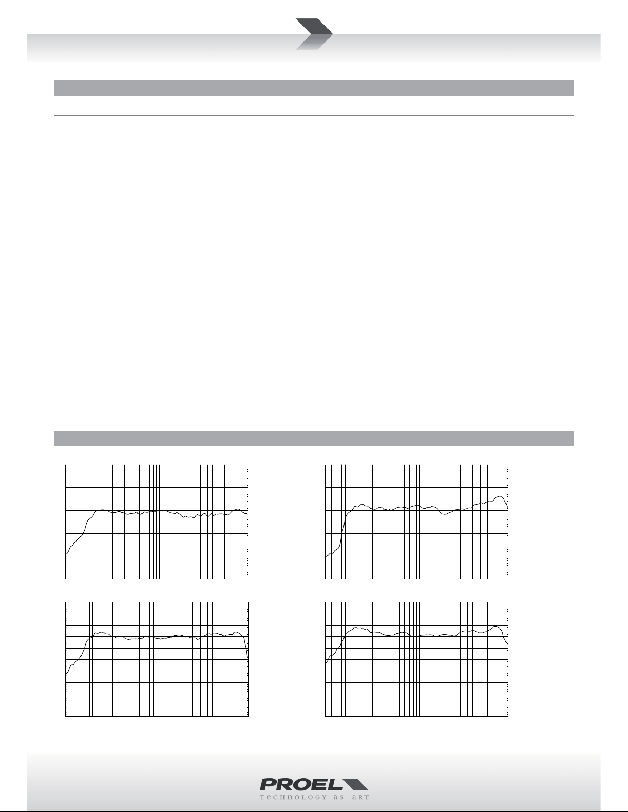
FREQUENCY RESPONSE . . . . . . . . . . . . . . . . . . . . . 3
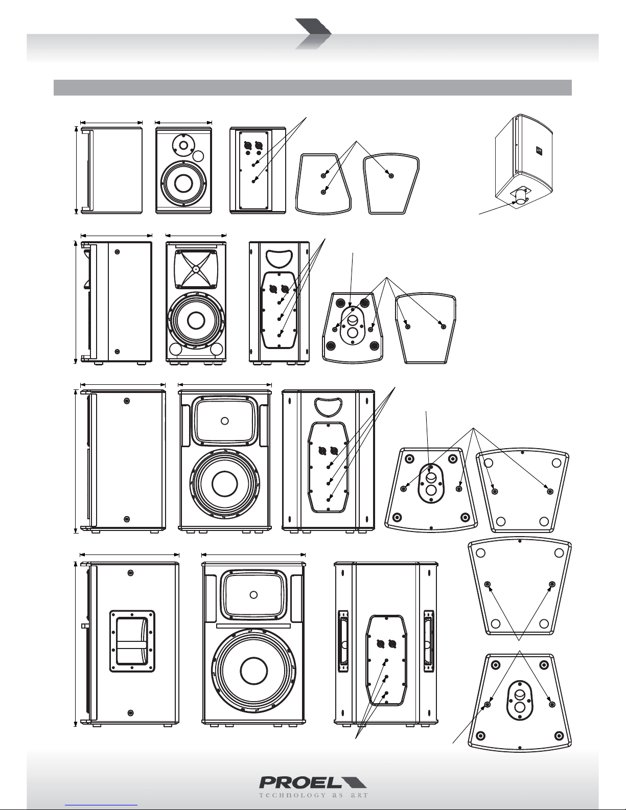
DIMENSIONS AND FLYING POINTS. . . . . . . . . . . . . 4
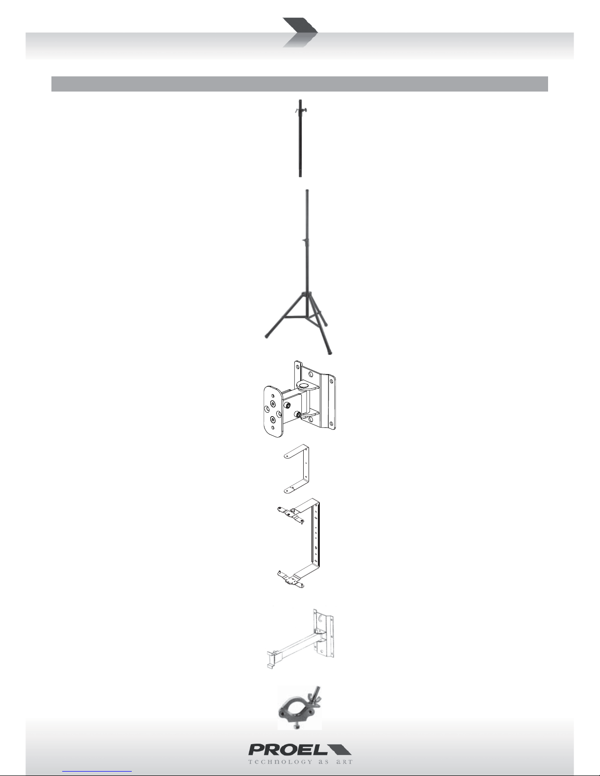
ACCESSORIES . . . . . . . . . . . . . . . . . . . . . . . . . . . . . 5
INPUT PANEL (FIG.1). . . . . . . . . . . . . . . . . . . . . . . . 6
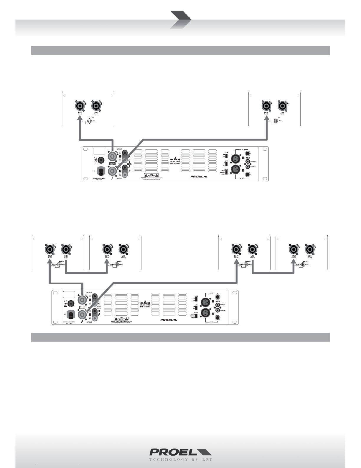
CONNECTIONS (FIG.2) . . . . . . . . . . . . . . . . . . . . . . 6
CONFIGURATIONS (FIG.3) . . . . . . . . . . . . . . . . . . . 7
SPARE PART LIST . . . . . . . . . . . . . . . . . . . . . . . . . . . 7
SAFETY AND PRECAUTIONS . . . . . . . . . . . . . . . . . . 8
IN CASE OF FAULT . . . . . . . . . . . . . . . . . . . . . . . . . . 8
TROUBLESHOOTING . . . . . . . . . . . . . . . . . . . . . . . . 8
CE CONFORMITY. . . . . . . . . . . . . . . . . . . . . . . . . . . 8
PACKAGING, SHIPPING AND COMPLAINT . . . . . . . 8
WARRANTY AND PRODUCTS RETURN . . . . . . . . . . 9
INSTALLATION AND DISCLAIMER . . . . . . . . . . . . . . 9
GENERAL INFORMATION . . . . . . . . . . . . . . . . . . . 10
INSTRUCTIONS (FIG. 1 / 2 / 3) . . . . . . . . . . . . . . . 10
INDICE
SPECIFICHE TECNICHE . . . . . . . . . . . . . . . . . . . . . . 3
RISPOSTA IN FREQUENZA. . . . . . . . . . . . . . . . . . . . 3
DIMENSIONI E PUNTI DI SOSPENSIONE. . . . . . . . . 4
ACCESSORI . . . . . . . . . . . . . . . . . . . . . . . . . . . . . . . 5
PANNELLO INGRESSI (FIG.1). . . . . . . . . . . . . . . . . . 6
CONNESSIONI (FIG.2) . . . . . . . . . . . . . . . . . . . . . . . 6
CONFIGURAZIONI (FIG.3). . . . . . . . . . . . . . . . . . . . 7
PARTI DI RICAMBIO. . . . . . . . . . . . . . . . . . . . . . . . . 7
AVVERTENZE PER LA SICUREZZA . . . . . . . . . . . . . 12
IN CASO DI GUASTO . . . . . . . . . . . . . . . . . . . . . . . 12
PROBLEMATICHE COMUNI. . . . . . . . . . . . . . . . . . 12
CONFORMITÀ CE. . . . . . . . . . . . . . . . . . . . . . . . . . 12
IMBALLAGGIO, TRASPORTO E RECLAMI . . . . . . . 12
GARANZIE E RESI . . . . . . . . . . . . . . . . . . . . . . . . . 13
INSTALLAZIONE E LIMITAZIONI D’USO. . . . . . . . . 13
INFORMAZIONI GENERALI . . . . . . . . . . . . . . . . . . 14
ISTRUZIONI (FIG. 1 / 2 / 3) . . . . . . . . . . . . . . . . . . 14

3
FREQUENCY RESPONSE RISPOSTA IN FREQUENZA
LT6P
MODEL LT6P LT8P LT10P LT12P
System type 2-way vented enclosure 2-way vented enclosure 2-way vented enclosure 2-way vented enclosure
High Frequency Device 1’’ neodymium tweeter 1’’ compression driver 1" VC 1’’ compression driver 1" VC 1’’ compression driver 1.35" VC
Low Frequency Device 6.5” woofer with 1" VC 8” woofer with 1.5" VC 10” woofer with 2" VC 12” woofer with 2.5" VC
Angular Coverage 60° H x 40° V 60° H x 40° V 90° H x 60° V 90° H x 60° V
Nominal Impedance 8 ohm 8 ohm 8 ohm 8 ohm
Power RaƟng (conƟnuous) 75 W 150 W 200 W 300 W
Power RaƟng (peak) 150 W 300 W 400 W 600 W
Frequency Response 75 Hz - 20 kHz 70 Hz - 20 kHz 60 Hz - 20 kHz 50 Hz - 20 kHz
SensiƟvity (1 W / 1 m) 88 dBspl 92 dBspl 94 dBspl 96 dBspl
Max SPL at 1mt (peak) 110 dBspl 117 dBspl 120 dBspl 124 dBspl
Crossover Frequency 2400 Hz 2400 Hz 2200 Hz 2200 Hz
Connectors INPUT, LINK:
Neutrik SPEAKON© (NL4MP)
6.3mm JACK female socket
INPUT, LINK:
Neutrik SPEAKON© (NL4MP) INPUT, LINK:
Neutrik SPEAKON© (NL4MP)
ConstrucƟon Plywood Plywood Plywood Plywood
Cabinet Colour Black or White Black or White Black or White Black or White
Finish An-scratch Paint An-scratch Paint An-scratch Paint An-scratch Paint
Flying System 1 x M4 top, 2 x M4 boom,
2 x M6 rear 4 x M8 top and boom,
3 x M6 rear 4 x M10 top and boom
3 x M6 rear
Handles - 1 x rear 1 x rear 2 x sides
MounƟng Pole 1 x boom 1 x boom, dual angle 1 x boom, dual angle 1 x boom, dual angle
Weight 4.9 kg (10.8 lb) 7.5 kg (16.5 lb) 11.5 kg (25.4 lb) 15.5 kg (34.2 lb)
Dimensions (W x H x D) 204 x 295 x 223 mm 220 x 442 x 260 mm 340 x 515 x 310 mm 380 x 595 x 360 mm
TECHNICAL SPECIFICATIONS SPECIFICHE TECNICHE
LT10P
LT8P
LT12P
10k
5k
2k1k
500
200
10050
40 20kHz
110
dBSPL
100
90
80
70
60 10k
5k
2k1k
500
200
10050
40 20kHz
110
dBSPL
100
90
80
70
60
10k
5k
2k1k
500
200
10050
40 20kHz
110
dBSPL
100
90
80
70
60 10k
5k
2k1k
500
200
10050
40 20kHz
110
dBSPL
100
90
80
70
60

4
DIMENSIONS AND FLYING POINTS DIMENSIONI E PUNTI DI SOSPENSIONE
29.5 cm
11.6"
22.3 cm
8.78"
20.4 cm
8.03"
M4 Flying points
M6 Flying Points
LT6 Pole adapter (supplied)
26.0 cm
10.2"
22.0 cm
8.66"
44.2 cm
17.4"
M8 Flying points
Dual Angle MounƟng Pole
51.5 cm
20.3"
31.0 cm
12.2"
34.0 cm
31.0"
M10 Flying Points
Dual Angle
MounƟng Pole
M6 Flying Points
M6 Flying Points
M10 Flying Points
Dual Angle
MounƟng Pole
M6 Flying Points
36.0 cm
14.2"
59.5 cm
23.4"
38.0 cm
15.0"

5
KPTLT8
C-shape metal bracket for wall mount of TL8P
with +/- 70° free rotaon.
KPTLT10
C-shape metal bracket for wall mount of TL10P
with +/- 70° free rotaon.
KPTLT12
C-shape metal bracket for wall mount of TL12P
with +/- 70° free rotaon.
KPTLT8
Supporto in metallo a C per montaggio a muro
della TL8P con rotazione di +/- 70°.
KPTLT10
Supporto in metallo a C per montaggio a muro
della TL10P con rotazione di +/- 70°.
KPTLT12
Supporto in metallo a C per montaggio a muro
della TL12P con rotazione di +/- 70°.
ACCESSORIES
KP210
Adjustable speaker pole for speaker-subwoofer separaon
with terminal pieces Ø 35 mm. Supplied with a bolt
locking mechanism incorporang a steel pin for extra
safety. Adjustment: 825 - 1320 mm.
ACCESSORI
KP210
Supporto distanziatore cassa-subwoofer regolabile in
acciaio con terminali Ø 35mm. Dotato di meccanismo
di chiusura a vite con pin di sicurezza in acciaio.
Regolazione: 825 - 1320 mm.
FRE300BK
Professional aluminium floor-stand for speaker
with terminal pieces Ø 35mm. Supplied with
a screw locking system, a steel safety pin and
“Aircushioned” air-damped release device to grant
a flexible, fast and easy adjustment. Adjustment:
1470-2180 mm.
FRE300BK
Supporto professionale in alluminio da pavimento
con terminali Ø 35mm. Con sistema di blocco a
vite, pin di sicurezza in acciaio e disposivo di
smorzamento ad aria per la massima velocità e
facilità di regolazione.
Regolazione: 1470-2180 mm.
KPTLT6
C-shape metal bracket for wall mount of TL6P
with +/- 30° free rotaon.
KPTNX04
Horizontal and Vercal adjustable metal bracket
for wall mount, bar length 25 cm, 12.5° 4 step
vert. aiming, 10° 7 step hor. aiming, must be
used in conjuncon with KPTLT8 / KPTLT10 /
KPTLT12.
PLH300
Single aluminium coupler for 50mm truss with M12
bolt, always use two couplers with the KPTLT8 /
KPTLT10 / KPTLT12 for each speaker.
KPTLT6
Supporto in metallo a C per montaggio a muro
della TL6P con rotazione di +/- 30°.
KPTNX04
Staffa in metallo regolabile in orizzontale e
vercale per montaggio a muro, lunghezza barra
25 cm, 4 passi a 12.5° in vercale e 7 passi a 10°
in orizzontale, deve essere usata con l'accessorio
KPTLT8 / KPTLT10 / KPTLT12.
PLH300
Accoppiatore per truss 50mm in alluminio
con bullone M12, usarne sempre due insieme
all'accessorio KPTLT8 / KPTLT10 / KPTLT12.
KPTLTP
Short aiming bracket for wall mount, 4 x 15°
vercal steps, free horizontal rotaon, the speaker
can be mounted both vercally or horizontally.
KPTLTP
Staffa corta per montaggio a muro, passi vercali
4 x 15°, rotazione orizzontale libera, l'altoparlante
può essere montato sia verticalmente che
orizzontalmente.

6
INPUT PANEL (FIG.1) PANNELLO INGRESSI (FIG.1)
CONNECTIONS (FIG.2) CONNESSIONI (FIG.2)
LOUDSPEAKER LINE LOSSES
(maximum permissible line lengths for 0.5dB losses, voltage or spl)
8 ohm load 4 ohm load Wire secon
data
PROEL recommended
cables
meter feet meter feet mm² AWG 2 wires
flex-black
2 wires FR
installaon
50 164 25 82 4.0 12 HPC624BK HPC624FRS
30 100 15 50 2.5 14 HPC620BK HPC620FRS
20 66 10 33 1.5 16 HPC610BK HPC610FRS
this is a short extracon of the wide assortment of cables available from
PROEL, please visit our website at www.proel.com
Perdite di collegamento
(massima lunghezza per perdite inferiori a 0.5dB, tensione o spl)
carico 8 ohm carico 4 ohm Sezione del
cavo
Cavi PROEL consiglia
metri feet metri feet mm² AWG 2 fili nero
flessibile
2 fili da in-
stallazione
50 164 25 82 4.0 12 HPC624BK HPC624FRS
30 100 15 50 2.5 14 HPC620BK HPC620FRS
20 66 10 33 1.5 16 HPC610BK HPC610FRS
questo è un breve estrao del vasto assormento di cavi disponibile da PROEL,
vi preghiamo di visitare il nostro sito web all'indirizzo www.proel.com
INPUT - LINK (ingresso-rilancio)
ConneƩore per cavo Ɵpo Speakon Neutrik NL2FX
PROEL code - NL2FX
Codice PROEL - NL2FX
PROEL code - J2C
Codice PROEL - J2C
INPUT - LINK
Neutrik NL2FX Speakon Cable Connector
INPUT - LINK (ingresso-rilancio)
Jack di potenza
INPUT - LINK
power Jack
Ɵp - posiƟve / red / rosso
sleeve - negaƟve / black / nero
1+
1-
20mm
0.8"
8mm
0.3"
RED
BLACK
posiƟve / red / rosso
1+
negaƟve / black / nero
1-
NOTA: IL CONNETTORE JACK È PRESENTE SOLO
SUL MODELLO LT6P.
NOTE: THE JACK CONNECTOR IS PRESENT ONLY
ON LT6P MODEL.

7
CONFIGURATIONS (FIG.3) CONFIGURAZIONI (FIG.3)
RIGHT
single speaker
8 ohm load
LEFT
single speaker
8 ohm load
LT passive BASIC STEREO sound system
RIGHT
paralled speakers
4 ohm load
LEFT
paralled speakers
4 ohm load
LT passive DOUBLE PARALLEL STEREO sound system
SPARE PART LIST PARTI DI RICAMBIO
CODE DESCRIPTION
96PCAGLT10P LT10P XOVER PCBA
96PCAGLT12P LT12P XOVER PCBA
96PCAGLT6P LT6P XOVER PCBA
96PCAGLT8P LT8P XOVER PCBA
98LT10WFZ8 WOOFER 10” 8 OHM (LT10P)
98LT12WFZ8 WOOFER 12” 8 OHM (LT12P)
98LT6TWZ8 TWEETER 1” 8 OHM (LT6)
98LT6WFZ8 WOOFER 6” 8 OHM (LT6P)
98LT8WFZ8 WOOFER 8” 8 OHM (LT8P)
98LTDR100Z8 DRIVER 1” 1” VC (LT SERIES)
98LTDR135Z8 DRIVER 1” 1.35” VC (LT SERIES)
NL4MP NL4MP NEUTRIK SPEAKON CONNECTOR
CODICE DESCRIZIONE
96PCAGLT10P CROSSOVER LT10P
96PCAGLT12P CROSSOVER LT12P
96PCAGLT6P CROSSOVER LT6P
96PCAGLT8P CROSSOVER LT8P
98LT10WFZ8 WOOFER 10” 8 OHM (LT10P)
98LT12WFZ8 WOOFER 12” 8 OHM (LT12P)
98LT6TWZ8 TWEETER 1” 8 OHM (LT6)
98LT6WFZ8 WOOFER 6” 8 OHM (LT6P)
98LT8WFZ8 WOOFER 8” 8 OHM (LT8P)
98LTDR100Z8 DRIVER 1” 1” VC (LT SERIES)
98LTDR135Z8 DRIVER 1” 1.35” VC (LT SERIES)
NL4MP CONNETTORE NL4MP NEUTRIK SPEAKON

8
SAFETY AND PRECAUTIONS
• CAUTION: before using this product read carefully the following safety instrucons. Take a look of this manual enrely and preserve it for
future reference.
When using any electric product, basic precauons should always be taken, including the following:
– To reduce the risk, close supervision is necessary when the product is used near children.
– Protect the apparatus from atmospheric agents and keep it away from water, rain and high humidity places.
– This product should be site away from heat sources such as radiators, lamps and any other device that generate heat.
– This product should be located so that its locaon or posion does not interfere with its proper venlaon and heang dissipaon.
– Care should be taken so that objects and liquids do not go inside the product.
– This product may be capable of producing sound levels that could cause
permanent hearing loss. Exposure to extremely high noise levels may cause
permanent hearing loss. Individuals vary considerably in suscepbility to noise-
induced hearing loss, but nearly everyone will lose some hearing if exposed
to sufficiently intense noise for a period of time. The U.S. Government’s
Occupational Safety and Health Administration (OSHA) has specified the
permissible noise level exposures shown in the following chart. According to
OSHA, any exposure in excess of these permissible limits could result in some
hearing loss. To ensure against potenally dangerous exposure to high sound
pressure levels, it is recommended that all persons exposed to equipment
capable of producing high sound pressure levels use hearing protectors while
the equipment is in operaon. Ear plugs or protectors in the ear canals or over
the ears must be worn when operang the equipment in order to prevent
permanent hearing loss if exposure is in excess of the limits set forth here. Keep
your's aenon that children and pets are more suscepble to excessive noise
levels.
IN CASE OF FAULT
• In case of fault or maintenance this product should be inspected only by qualified service personnel when:
– There is a flaw either in the connecons or in the supplied connecng cables.
– Liquids have spilled inside the product.
– The product has fallen and been damaged.
– The product does not appear to operate normally or exhibits a marked change in performance.
– The product has been lost liquids or gases or the enclosure is damaged.
• Do not operate on the product, it has no user-serviceable parts inside, refer servicing to an authorized maintenance centre.
TROUBLESHOOTING
No Sound • Is the loudspeaker cable connected?
• Is the SPEAKON cable connector correctly inserted? turn it clockwise unl it clicks.
• Are you sure your power cable works properly? check it using a cable tester or replacing with a newone.
As soon as the music gets loud,
the high frequency shuts down
• The HF driver protecon trips to protect the HF driver from excessive signal: turn down the volume and
mid/high tone controls.
Distorted Sound • Input signal level is too high. Turn down your level controls.
Different channel level • Check if are using a balanced cable for one channel and an unbalanced one for the other, as this would
cause a considerable difference in channel levels.
• Be sure that your loudspeaker system is fully connected and both loudspeakers have the same
impedance.
Noise / Hum • Enable GND LIFT buon on rear panel, if the problem persist press all GND LIFT buons for all system's
amplifiers.
• Whenever possible, preferably use only balanced cables. Unbalanced lines may also be used but may result
in noise over long cable runs.
• Somemes it helps to plug all audio equipment into the same AC circuit so they share a common ground.
CE CONFORMITY
• Proel products comply with direcve 2004/108/EC (EMC), as stated in EN 55103-1 and EN 55103-2 standards and with direcve 2006/95/CE
(LVD), as stated in EN 60065 standard.
• Under the EM disturbance, the rao of signal-noise will be changed above 10dB.
PACKAGING, SHIPPING AND COMPLAINT
• This unit package has been submied to ISTA 1A integrity tests. We suggest you control the unit condions immediately aer unpacking it.
• If any damage is found, immediately advise the dealer. Keep all unit packaging parts to allow inspecon.
• Proel is not responsible for any damage that occurs during shipment.
• Products are sold “delivered ex warehouse” and shipment is at charge and risk of the buyer.
• Possible damages to unit should be immediately nofied to forwarder. Each complaint for package tampered with should be done within eight
days from product receipt.
Duraon Per Day
In Hours
Sound Level dBA
Slow Response
Typical
Example
8 90 Duo in small club
692
4 95 Subway Train
397
2 100 Very loud classical music
1.5 102
1 105 Traffic noise
0.5 110
0.25 or less 115 Loudest parts at a rock concert

9
WARRANTY AND PRODUCTS RETURN
• Proel products have operang warranty and comply their specificaons, as stated by manufacturer.
• Proel warrants all materials, workmanship and proper operaon of this product for a period of two years from the original date of purchase. If
any defects are found in the materials or workmanship or if the product fails to funcon properly during the applicable warranty period, the owner
should inform about these defects the dealer or the distributor, providing receipt or invoice of date of purchase and defect detailed descripon.
This warranty does not extend to damage resulng from improper installaon, misuse, neglect or abuse. Proel S.p.A. will verify damage on returned
units, and when the unit has been properly used and warranty is sll valid, then the unit will be replaced or repaired. Proel S.p.A. is not responsible
for any "direct damage" or "indirect damage" caused by product defecveness.
INSTALLATION AND DISCLAIMER
• Proel products have been expressly designed for audio applicaon, with signals in audio range (20Hz to 20kHz). Proel has no liability for damages
caused in case of lack of maintenance, modificaons, improper use or improper installaon non-applying safety instrucons.
• The installaon of these speakers is provided for indoors, in case of use outdoors be sure that the speakers are installed correctly in a safe
locaon protected from wind, rain and humidity. To avoid performance deterioraon of mechanical, acouscs and electrical parts is not advisable
to leave these speakers exposed outdoors for a long period of me, so we suggest a temporary installaon for the limited sound events.
• The installaon of these speakers is provided for floor or by means of specific stands able to support their weight. Therefore avoid installaon
on unstable elements such as: furniture, chairs and vibrant surfaces as stages or other speakers without appropriate fix point specifically designed
to avoid speaker movement. Then avoid the use of inadequate supports, we suggest to use PROEL stands and accessories only.
• In case of the speakers are provided of rigging points: DO NOT SUSPEND THE SPEAKERS FROM THE HANDLES, use exclusively these rigging points.
Consult professional rigger or structural engineers prior to suspending loudspeakers from a structure not intended for that use. Always know the
working load limit of the structure supporng the loudspeakers. Always make sure that the rigging hardware minimum rang is at least five mes
the actual load, speakers and rigging hardware.
• Locate the speakers as far away as possible from radio or television receivers or other sensive equipment. These speakers have a strong
magnec field which can induce hum and noise into unshielded devices that are located nearby with consequent deterioraon of recepon of
image and sound.
• Proel S.p.A. reserves the right to change these specificaons at any me without noce.
• Proel S.p.A. declines any liability for damages to objects or persons caused by lacks of maintenance, improper use, installaon not performed
with safety precauons and at the state of the art.

10
GENERAL INFORMATION
Thank you for having chosen a PROEL product.
The LITE Series by PROEL is an extended range of acve and passive speaker systems with plywood cabinet offering the
renowned PROEL sound and a high-level performance in a reliable and affordable package. For the construcon of the
cabinets we have used plywood, a very lightweight and durable material that makes moving and installing these speakers
very quick and easy. Strong, an-scratch paint and steel grilles with an internal foam layer provide proper protecon
for years of service. The dual-angle pole holder featured in LT8, LT10 and LT12 models offers the possibility to obtain a
more uniform coverage of the audience.
For the high frequency reproducon of LITE Series we have designed wide-dispersion horns, able to provide constant
coverage for large audiences and detailed response with low distoron. The high-excursion woofers, together with
carefully tuned vented cabinets, offers an extended response with deep and ght basses.
4 passive models are available, featuring carefully designed crossover filters with HF electronic protecon. The choice
of black or white cabinet, built-in flying points and a wide range of accessories make them suitable for any kind of fixed
installaon.
The LT loudspeaker systems can be combined with the SW subwoofers capable of providing the perfect low frequency
extension for each model of the series.
INSTRUCTIONS (FIG. 1 / 2 / 3)
1. INPUT (SPEAKON)
External amplifier power input: this is the connector where you plug in the power cable coming from your power
amplifier or powered mixer. The powered signal is filtered by an internal passive crossover that splits the power signal
into a low frequency secon, sent to the woofer, and a high frequency secon, sent to the tweeter/driver. The frequency
transion is around 2KHz. The INPUT has this pin connecon:
PIN1+ (or TIP): posive power signal (usually red wire)
PIN1- (or SLEEVE): negave power signal (usually black wire)
2. LINK (SPEAKON)
Output of the power signal to be sent to an another satellite loudspeaker. INPUT and LINK connectors are connected
in parallel.
CHOOSE THE AMPLIFIER POWER
We give you two power-handling numbers: AES or CONTINUOUS, and PEAK. These data suggest you can use any amplifier
with a power capability equal or less the power-handling, but this rule is valid only if the amplifier never clips.
Prevenng loudspeaker damage caused by clipping, that is likely the number one cause of damage, and assuming you
want to use the full capability of the loudspeaker, we recommend the use of an amplifier with a built-in limiter to prevent
clipping: in this case the rated power capability must be the same as the connuous power rang of the loudspeaker
into the same specified impedance (pically 4 or 8 ohms):
• To obtain the best result using 4 (as single 8 ohm speaker for each channel) to 8 (as parallel 4 ohm speaker for each
channel) LT6P connected in stereo, we suggest the use of PROEL AUP4150 amplifier.
• To obtain the best result using 2 (as single 8 ohm speaker for each channel) to 4 (as parallel 4 ohm speaker for each
channel) LT8P connected in stereo, we suggest the use of PROEL HPX-900 amplifier.
• To obtain the best result using 2 (as single 8 ohm speaker for each channel) to 4 (as parallel 4 ohm speaker for each
channel) LT10P connected in stereo, we suggest the use of PROEL HPX-900 or HPX-1200 amplifier.
• To obtain the best result using 2 (as single 8 ohm speaker for each channel) to 4 (as parallel 4 ohm speaker for each
channel) LT12P connected in stereo, we suggest the use of PROEL HPX-1200 amplifier.
IMPORTANT: Clipping occurs when the signal at the output of any device in the system (not just the amplifier) reaches its
maximum level. Proper operaƟon of a sound system includes being aware of the types of audio signals being reproduced,
controlling the output levels accordingly, and operaƟng all the devices in the system so that no clipping occurs within
the signal chain.

11

12
AVVERTENZE PER LA SICUREZZA
• ATTENZIONE: Durante le fasi di uso o manutenzione, devono essere prese alcune precauzioni onde evitare danneggiamenalle struure
meccaniche ed eleroniche del prodoo.
Prima di ulizzare il prodoo, si prega di leggere aentamente le seguenistruzioni per la sicurezza. Prendere visione del manuale d’uso e
conservarlo per successive consultazioni:
– In presenza di bambini, controllare che il prodoo non rappresenun pericolo.
– Posizionare l’apparecchio al riparo dagli agenatmosferici e a distanza di sicurezza dall’acqua, dalla pioggia e dai luoghi ad alto grado di
umidità.
– Collocare o posizionare il prodoo lontano da fondi calore quali radiatori, griglie di riscaldamento e ogni altro disposivo che produca
calore.
– Collocare o posizionare il prodoo in modo che non ci siano ostruzioni alla sua propria venlazione e dissipazione di calore.
– Evitare che qualsiasi oggetto o sostanza liquida entri all’interno del
prodoo.
– Questo prodoo può essere capace di produrre livelli sonori che possono
causare perdite d’udito permanen. Si raccomanda di evitare l’esposizione
ad allivelli sonori o livelli non confortevoli per lunghi periodi di tempo.
Se si notano perdite d’udito o acufeni (fischi) consultare un audiologo. La
sensibilità alla perdita di udito causata da eccessiva esposizione al rumore varia
considerevolmente da individuo a individuo, ma mediamente ciascuno può
accusare perdita di udito se esposto al rumore per un certo periodo di tempo.
Come suggerimento viene riportata la tabella dei tempi massimi di esposizione
giornaliera al rumore al fine di evitare perdite di udito, fonte della tabella è
l'ente per la salute degli StaUni(OSHA).
Si fa presente inoltre che sia i bambini che gli animali domesci sono più
sensibili al rumore intenso.
IN CASO DI GUASTO
• In caso di guasto o manutenzione questo prodoo deve essere ispezionato da personale qualificato quando:
– Ci sono difesulle connessioni o sui cavi di collegamento in dotazione.
– Sostanze liquide sono penetrate all’interno del prodoo.
– Il prodoo è caduto e si è danneggiato.
– Il prodoo non funziona normalmente esibendo una marcato cambio di prestazioni.
– Il prodoo perde sostanze liquide o gassose o ha l’involucro danneggiato.
• Non intervenire sul prodoo. Rivolgersi a un centro di assistenza autorizzato Proel.
PROBLEMATICHE COMUNI
Nessun Suono • È collegato il cavo degli altoparlan?
• È il conneore SPEAKON del cavo altoparlancorreamente inserito? girarlo finché non si sente il click.
• Sei sicuro che il cavo di segnale sia in buono stato? controlla il cavo con un tester oppure sostuiscilo
con un'altro.
Quando il suono è molto forte,
le alte frequenze svaniscono
• La protezione del driver HF interviene per proteggere il driver HF da una eccessivo segnale: abbassare il
volume e i controlli di tono delle frequenze medie e alte.
Suono Distorto • Il livello del segnale di ingresso è troppo alto, abbassare i controlli del livello.
Livello differente sui canali • Controllare se si stanno usando cavi bilanciasu un canale e sbilanciasull'altro, ciò può comportare
una notevole differenza di livello sui canali.
• Assicurarsi che gli altoparlansiano completamente collegae abbiano la medesima impedenza.
Rumore / Ronzio • Abilitare l'interruore GND LIFT sul pannello posteriore, se il problema persiste premere i GND LIFT su
tugli amplificatori del sistema.
• Qualora possibile, usare preferibilmente solo cavi bilancia. Cavi sbilanciapossono essere usama
risultano rumorosi su lunghe distanze.
• Talvolta può essere di aiuto alimentare tuo l'equipaggiamento audio collegandolo dalla stessa linea di
corrente AC, in modo che tugli apparacondividano la stessa presa di terra.
CONFORMITÀ CE
• I ProdoProel sono conformi alla direva 2004/108/EC (EMC), secondo gli standard EN 55103-1 ed EN 55103-2 ed alla direva 2006/95/CE
(LVD), secondo lo standard EN 60065.
• Se sooposto a disturbi EM, il rapporto segnale-rumore può essere superiore a 10dB.
IMBALLAGGIO, TRASPORTO E RECLAMI
• L’imballo è stato sooposto a test di integrità secondo la procedura ISTA 1A. Si raccomanda di controllare il prodoo subito dopo l’apertura
dell’imballo.
• Se vengono riscontradanni informare immediatamente il rivenditore. Conservare quindi l’imballo completo per permeerne l’ispezione.
• Proel declina ogni responsabilità per danni causadal trasporto.
• Le merci sono vendute “franco nostra sede” e viaggiano sempre a rischio e pericolo del distributore.
• Eventuali avarie e danni dovranno essere contestaal veore. Ogni reclamo per imballi manomessi dovrà essere inoltrato entro 8 giorni dal
ricevimento.
Ore di esposizione
giornaliera
Livello sonoro in dBA
costante di tempo SLOW
Esempio
Tipico
8 90 Duo acusco in un piccolo club
692
4 95 Treno metropolitano
397
2 100 Musica classica molto forte
1.5 102
1 105 Rumore da traffico urbano intenso
0.5 110
0.25 or less 115 Parte più rumorosa di un concerto rock

13
GARANZIE E RESI
• I ProdoProel sono provvisdella garanzia di funzionamento e di conformità alle proprie specifiche, come dichiarate dal costruore.
• La garanzia di funzionamento è di 24 mesi dopo la data di acquisto. I diferilevaentro il periodo di garanzia sui prodovendu, aribuibili a
materiali difeosi o difedi costruzione, devono essere tempesvamente segnalaal proprio rivenditore o distributore, allegando evidenza scria
della data di acquisto e descrizione del po di difeo riscontrato. Sono esclusi dalla garanzia difecausada uso improprio o manomissione. Proel
SpA constata tramite verifica sui resi la difeosità dichiarata, correlata all’appropriato ulizzo, e l’effeva validità della garanzia; provvede quindi
alla sostuzione o riparazione dei prodo, declinando tuavia ogni obbligo di risarcimento per danni direo indireeventualmente derivan
dalla difeosità.
INSTALLAZIONE E LIMITAZIONI D’USO
• I ProdoProel sono desnaesclusivamente ad un ulizzo specifico di po sonoro: segnali di ingresso di po audio (20Hz-20kHz). Proel declina
ogni responsabilità per danni a terzi causada mancata manutenzione, manomissioni, uso improprio o installazione non eseguita secondo le
norme di sicurezza.
• L'installazione di quesaltoparlanè prevista per uso interno, in caso di ulizzo all'esterno assicurarsi che gli altoparlansiano installa
correamente in un luogo sicuro e proteo dal vento, pioggia e umidità. Al fine di non deteriorarne le prestazioni meccaniche, acusche ed
eleriche non è consigliato lasciare quesaltoparlanesposall'aperto per lunghi periodi di tempo, si consiglia pertanto una installazione
temporanea all'evento da sonorizzare.
• L'installazione di quesaltoparlanè prevista a pavimento o tramite specifici supporadeguaal peso da sostenere. Pertanto evitare
l'installazione su elemeninstabili quali: mobili, sedie e superfici vibranquali palchi e altri altoparlannon dotadi fissaggi aa evitare
spostamendell'altoparlante. Quindi evitare di ulizzare suppornon adegua, si consiglia di usare solo i supporsuggerida PROEL.
• Qualora gli altoparlansiano munidi pundi fissaggio per la sospensione: NON SOSPENDERE GLI ALTOPARLANTI DALLE MANIGLIE usare
esclusivamente quespundi fi
ssaggio. Consultare arezzisprofessioniso ingegneri struurali prima di sospendere altoparlanda struure non
intese per questo specifico scopo. Non superare il limite di carico della struura che sosterrà gli altoparlan. Assicurarsi che tue le meccaniche
di sostegno siano in grado di sopportare un peso almeno 5 volte superiore al carico degli altoparlanincluse le meccaniche di sospensione.
• Nel caso di installazioni sospese di altoparlanavi in cui non sia possibile l'uso dei singoli interruori degli altoparlanper l'accensione e lo
spegnimento dei medesimi, si raccomanda l'installazione di interruori sulle linee di alimentazione della rete elerica, a tale proposito consultare
un esperto elericista per il correo dimensionamento dell'impianto elerico.
• Installare quesaltoparlanil più lontano possibile da radioricevitori e televisori. Un altoparlante installato in prossimità di quesapparapuò
causare interferenza e rumore con conseguente degrado della ricezione di immagini e suoni.
• La Proel S.p.a. si riserva di modificare il prodoo e le sue specifiche senza preavviso.
• Proel declina ogni responsabilità per danni a terzi causada mancata manutenzione, manomissioni, uso improprio o installazione non eseguita
secondo le norme di sicurezza e a regola d'arte.

14
INFORMAZIONI GENERALI
Grazie per aver scelto un prodoo PROEL.
La nuova serie LITE di PROEL è un’ampia gamma di diffusori avi e passivi in legno mulstrato in grado di offrire la
qualità del suono PROEL e performances elevate in prodoaffidabili e convenien. Per la realizzazione dei cabinets
è stato ulizzato legno mulstrato, un materiale estremamente leggero e resistente in grado di rendere il trasporto
e l’installazione di quesdiffusori molto semplice e rapido. La resistente vernice an-graffio e la griglia metallica con
spugna proteva assicurano anni di ulizzo senza problemi. La flangia per stavo a doppio angolo di inclinazione (nei
modelli da LT8, LT10 , LT12) consente di oenere una diffusione sonora più uniforme.
Per la riproduzione delle alte frequenze della serie LITE abbiamo progeato trombe ad ampia dispersione che forniscono
una copertura uniforme anche in ambiendi grandi dimensioni. I woofers a lunga escursione, insieme ai cabinet
accuratamente accorda, offrono una risposta estesa con bassi profondi e incisivi.
Sono disponibili 4 modelli passivi, equipaggiacon filtri di crossover con protezione HF accuratamente progea. La
scelta del colore nero o bianco per il cabinet ed una ampia gamma di accessori li rende perfeper qualunque po di
installazione fissa.
I diffusori della serie LITE possono essere abbinacon i subwoofer della serie SW in grado di estendere le basse
frequenze di ciascuno dei modelli LT.
ISTRUZIONI (FIG. 1 / 2 / 3)
1. INPUT (ingresso SPEAKON)
Ingresso del segnale di potenza proveniente da un amplificatore esterno: questo è il conneore dove inserire il cavo di
potenza proveniente dall'amplificatore di potenza o dal mixer amplificato. Il segnale di potenza è filtrato da un crossover
passivo interno che divide il segnale di potenza in parte bassa, inviata al woofer, e parte alta, inviata al tweeter/driver.
La frequenza di crossover è circa a 2KHz. L'ingresso speakon INPUT ha queste connessioni:
PIN1+ (o punta jack TIP): segnale di potenza posivo (solitamente filo rosso)
PIN1- (o anello jack SLEEVE): segnale di potenza negavo (solitamente filo nero)
2. LINK (uscita SPEAKON)
Uscita del segnale di potenza da inviare ad un altro diffusore acusco. I conneori INPUT e LINK sono collegain
parallelo tra loro.
SCELTA DELL' AMPLIFICATORE DI POTENZA
Sono fornidue dadi potenza applicabile: AES (connua), PEAK (di picco).
Perciò quesdasuggeriscono di usare un qualsiasi amplificatore con una capacità di potenza uguale o inferiore alla
potenza applicabile, ma questa regola è valida solo se l'amplificatore non satura (clip) mai.
Per prevenire i danni all'altoparlante causadal clip, che è la principale causa di guas, e supponendo che si voglia
usare l'altoparlante al massimo delle sue possibilità, è consigliato l'uso di un amplificatore con incorporato il limiter di
prevenzione del clip, in questo caso la capacità di potenza dell'amplificatore deve essere la stessa potenza applicabile
all'altoparlante alla stessa specifica impedenza (picamente 4 o 8 ohm):
• Per oenere il miglior risultato usando 4 (come singolo altoparlante a 8 ohm per canale) o 8 (come doppio altoparlante
a 4 ohm per canale) LT6P collegate stereo, si suggerisce l'uso dell'amplificatore PROEL AUP4150.
• Per oenere il miglior risultato usando 2 (come singolo altoparlante a 8 ohm per canale) o 4 (come doppio altoparlante
a 4 ohm per canale) LT8P collegate stereo, si suggerisce l'uso dell'amplificatore PROEL HPX-900.
• Per oenere il miglior risultato usando 2 (come singolo altoparlante a 8 ohm per canale) o 4 (come doppio altoparlante
a 4 ohm per canale) LT10P collegate stereo, si suggerisce l'uso dell'amplificatore PROEL HPX-900 o HPX-1200.
• Per oenere il miglior risultato usando 2 (come singolo altoparlante a 8 ohm per canale) o 4 (come doppio altoparlante
a 4 ohm per canale) LT12P collegate stereo, si suggerisce l'uso dell'amplificatore PROEL HPX-1200.
IMPORTANTE: Il clip avviene qualora il segnale all'uscita di un qualsiasi dispositivo nel sistema (non solo
l'amplificatore) raggiunge il suo massimo livello. Un'appropriato uso di un sistema audio richiede di essere consapevoli
del po di segnale audio riprodoo, regolando i livelli di uscita di conseguenza, e agendo in modo che non avvenga
nessun clip sul percorso del segnale fra tui disposivi audio coinvol.

15

REV. 13/14 CODE 96MAN0091
PROEL S.p.A.
(World Headquarter)
Via alla Ruenia 37/43
64027 Sant’Omero (TE) - ITALY
Tel: +39 0861 81241
Fax: +39 0861 887862
www.proel.com
This manual suits for next models
3
Table of contents
Languages:
Other PROEL Speakers manuals

PROEL
PROEL H15S User manual

PROEL
PROEL WX8A User manual

PROEL
PROEL ARTIA Series User manual

PROEL
PROEL SESSION 1 FREE User manual

PROEL
PROEL HSPL40 User manual

PROEL
PROEL FREE8LT User manual

PROEL
PROEL Freepass6 User manual

PROEL
PROEL XE51CTX User manual

PROEL
PROEL FREE1 User manual

PROEL
PROEL A31T User manual

PROEL
PROEL WAVE10P User manual

PROEL
PROEL NEXT User manual

PROEL
PROEL Edge C12A User manual

PROEL
PROEL FREE50V3 User manual

PROEL
PROEL WD10P User manual

PROEL
PROEL FLASH5 User manual

PROEL
PROEL SMART V plus User manual

PROEL
PROEL CSB10 User manual

PROEL
PROEL FLASH15A V2 User manual

PROEL
PROEL V12PLUS User manual