®
Instalación
1. Para la instalación convencional de la montura para la salida
posterior colgable en la pared, se deberá usar un sistema
de soporte de 4 pernos para adaptar el tanque de agua al
sistema de soporte y al drenaje. Consulte las instrucciones
de instalación que se incluyen con el sistema de anclaje del
tanque para la instalación de la unidad.
2. Si va a instalar el inodoro sobre un sistema de anclaje
existente, asegúrese de que el mismo cumpla con los
requisitos locales y de que el sistema de soporte resista
el peso para los requisitos de la aplicación.
3. Los vástagos de montura deben sobresalir 5/16"(8mm) de
la pared terminada.
4. Colocar las tuercas de seguridad que se entregaron con el
soporte o el apoyo en el perno prisionero de la montura
# 1, # 3 y # 4. No se usa tuerca de seguridad en la montura
del perno prisionero # 2. Ajustar las dos tuercas inferiores
de tal forma que estén separadas 1/16"de la pared
terminada. Usando un nivel, ajustar la tuerca de respaldo
del perno de montaje # 1 hasta un plano vertical con el
perno prisionero de montaje N.º 3.
Nota: Si la pared está irregular, las tres tuercas y
arandelas de respaldo se deberán colocar de tal forma
que quede un espacio mínimo de 1/16"entre la montura
y la pared.
5. Nota: Las tuercas de respaldo también conocidas como
tuercas de conexión, se deben colocar de tal forma que
lleven toda la carga de la montura, dejando un espacio
de 1/6"entre la montura y la pared terminada. Siga las
recomendaciones del fabricante para la conexión de salida
del portador. Al colocar la montura en el portador no se
recomienda usar un anillo de cera, se recomienda usar
fieltro o neopreno. Al colocar la montura en el portador, el
empaque del drenaje se deberá comprimir lo suficiente
para asegurar un sellado positivo del gas y un sellado
impermeable.
6. Con ayuda de dos personas, instale la taza sobre los pernos
prisioneros del montaje. Coloque la arandela de fibra que se
incluye con la montura del portador, sobre los pernos #1,
#3 y #4. Coloque el tapón de la tuerca que se incluye en el
portador, sobre los pernos prisioneros de montaje #1, #3
y #4. Mientras que se sostiene la taza nivelada y usa una
llave ajustable, ajuste las tres tapas de las tuercas hasta
que estén ceñidas. ADVERTENCIA: EL PRODUCTO ES
FRÁGIL No ajuste demasiado. Solo debe quedar ceñido.
7. Instale la arandela de fibra y el tapón de la tuerca en el
perno de montaje #2, ajuste manualmente hasta que
la tuerca y la arandela toquen la porcelana. Ajuste
manualmente el tapón de tuerca firmemente contra la
porcelana. Eso es tolo lo que se necesita para montar la
tuerca y la arandela en el perno #2. Selle con silicona de
caucho la separación entre el inodoro y la pared terminada.
Nota: Si ajusta con llave el tapón de tuerca en el perno de
montaje #2, romperá la porcelana debido a que no hay
tuerca de respaldo en este perno.
8. Colocando la parte estrecha del empaque grande de goma
de cara contraria al tanque, deslice el empaque de goma
sobre la rosca de la válvula de desagüe al fondo del tanque.
Conecte el tubo flexible de suministro de agua (no incluido)
dentro de la válvula de llenado del tanque. Coloque el
tanque sobre la taza, con el lado estrecho del empaque de
goma grande viendo hacia la taza. Al mismo tiempo que
coloca el tanque sobre la taza, dirija el tubo de suministro
flexible a través de la apertura que se proporciona.
9. Coloque el empaque pequeño de goma sobre los pernos de
montura del tanque que se incluyen en el tanque. Coloque
la arandela metálica y la tuerca en el fondo de las tuercas
del tanque, y ajustarlas hasta que el tanque esté ceñido
contra la barra del tanque sanitario del tanque. Conecte
la línea de suminstro del tanque a la llave de paso y ajuste
firmemente todas las tuercas de acoplamiento. Abra
elsuministro de agua y permita que se llene el tanque.
Revise que no haya fugas y ajuste la montura como sea
necesario.
Nota: La perspectiva de esta ilustración es una representación
general y puede no necesariamente definir los contornos
exactos del producto.
A
B
C
D
Recommended Tools & Materials
(A) Regular Screwdriver
(B) Adjustable Wrench
(C) Marker
(D) Tape Measure
(E) Level
(F) Silicone Sealant
(G) Putty Knife
(H) Flexible Supply Tube (Not Included)
(I) Closet Carrier/Support (Not Included)
CAUTION: PRODUCT IS FRAGILE
Handle with care to avoid breakage and possible injury!
When performance matters.
When performance matters.
Note: Views in this illustrations are for general representation
and may not necessarily define the exact contours of the product.
7730/7730HE
REV 10/2013
-1-
If you are installing the toilet on an existing support system,
make sure the system is in compliance with local code
requirements and the support system is weight rated for
the application requirements.
12
EG
F
If replacing an existing toilet be certain to shut off
water supply before removing old toilet.
SINK INSTALLATION:
34
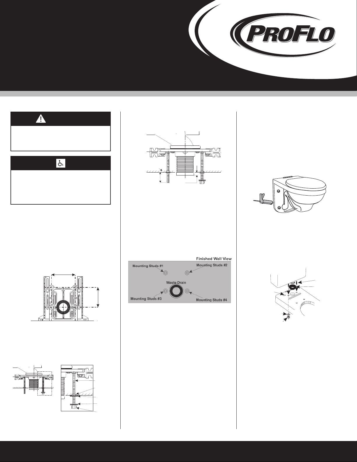
Wall Hung Back Outlet Toilet with Tank Installation
For typical installation of the wall hung back outlet fixture, a
4-bolt Carrier/Support system, (not supplied with this unit)
must be used for attaching the water closet to the carrier/support
system and waste drain. Refer to the Installation Instructions
that were supplied with the Closet Carrier/Support System for
installation of the unit.
H
Place back up nuts supplied with the carrier/support on mounting
stud #1, #3 and #4. No back-up nut is used on mounting
stud #2! Adjust the two lower back-up nuts so the front face of
the nuts are 1/16”away from the finished wall. Using a level,
adjust the back-up nut on mounting stud #1 to a vertical plane
with mounting stud #3. Place back-up washer on the three
installed back-up nuts.
Note; If the wall is irregular, the three back-up nuts and
washers must be positioned to allow a minimum of 1/16”
gap between the fixture and the wall.
7-1/2”
(190mm)
9”(228mm)
I
Vista frontal Corte de los accesorios de montaje
For installations where consideration is given for
ADA compliance, the seat height must be 17”to
19”(432 to 483) from the finished floor.
Pernos de montaje N.º 1
vista de la pared terminada
Pernos de montaje N.º 2
Pernos de montaje N.º 3 Pernos de montaje N.º 4
Drenaje residual
pernos de
montaje
2-1/8”
(54mm)
tuerca de
respaldo
tuerca de
respaldo
arandela de
fibra
tapa de la
tuerca
cabezal de
desague
5/16”
(8mm)
Mounting studs should extend 2-1/8”(54mm) beyond the
finished wall.
The waste horn should extend 5/16”(8mm) beyond the
finished wall.
pared terminada
vista superior
del transportador
Rubber
Gasket
Tank
Bolts
Tank
Washers
Tank Nuts
-2-
Note: The back-up nuts, also referred to as the
bearing nuts, must be set to take the full loading
from the fixture while allowing a 1/6”clearance
between the fixture and the finished wall.
Follow the carrier manufacturer’s recommendation
settings for the outlet connection.
When setting fixture onto the carrier, it is not
recommended to use a wax ring, felt or neoprene
are recommended.
When setting the fixture to the carrier, the waste
gasket must be compressed sufficiently to assure
a positive gas and watertight seal.
56
78
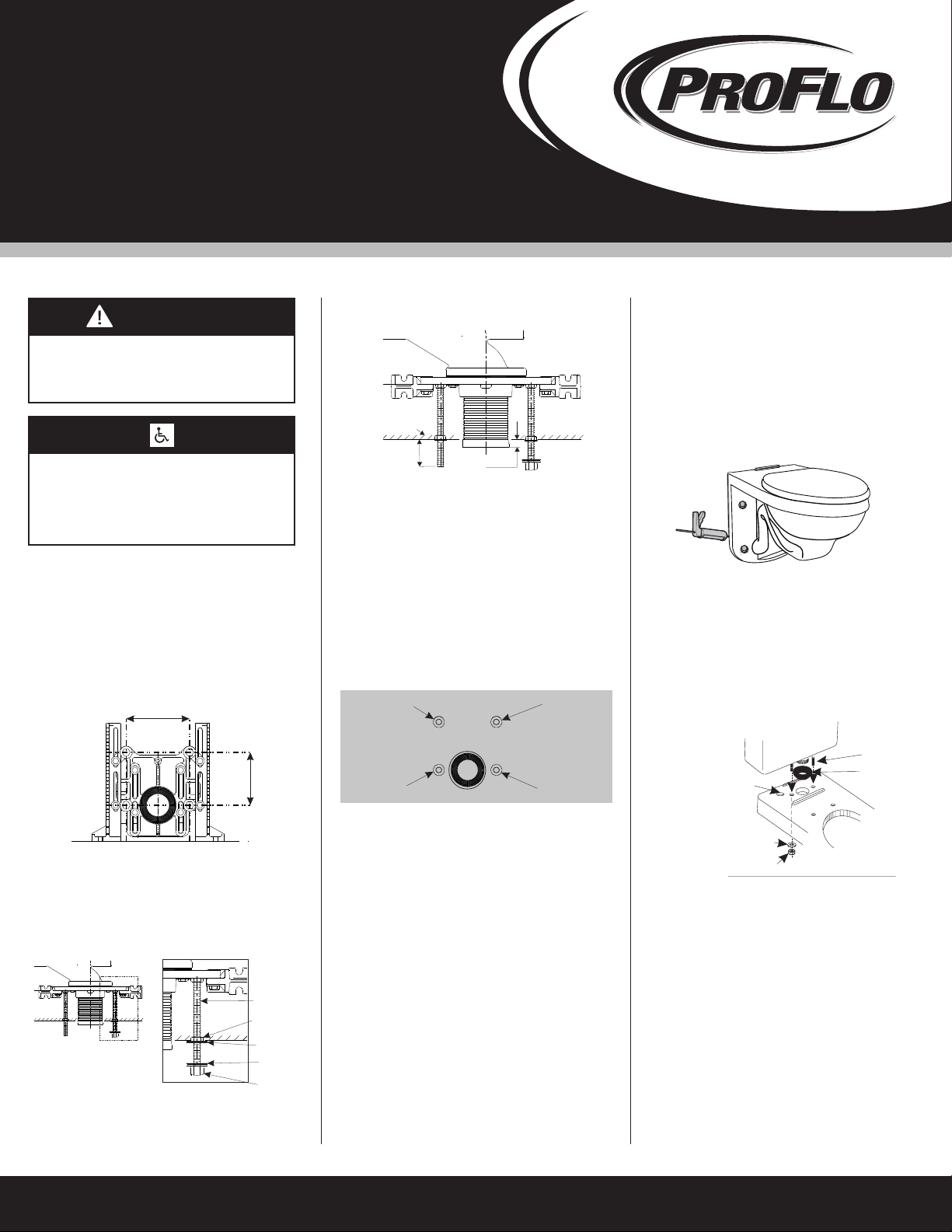
Install the fiber washer and cap nut onto the mounting
stud #2, hand tighten until the nut and washer are
touching the china. Hand snug firmly the cap nut against
the china, this is all that is necessary for mounting the
cap nut and washer to stud #2.
.
Caulk sealant into the gap between the toilet and the
finished wall.
Using two people, install the bowl onto the fixture mounting
studs.
Place the fiber washer supplied with the carrier/support on
mounting studs #1, #3 and #4. (Do not place a fiber
washer or cap nut on mounting stud #2 at this time.)
Place the cap nut supplied with the carrier/support on
mounting studs #1, #3 and #4. While holding the bowl
level and using an adjustable wrench, tighten the three
cap nuts until they are snug.
CAUTION: PRODUCT IS FRAGILE
Do not over tighten nuts more than a snug fit.
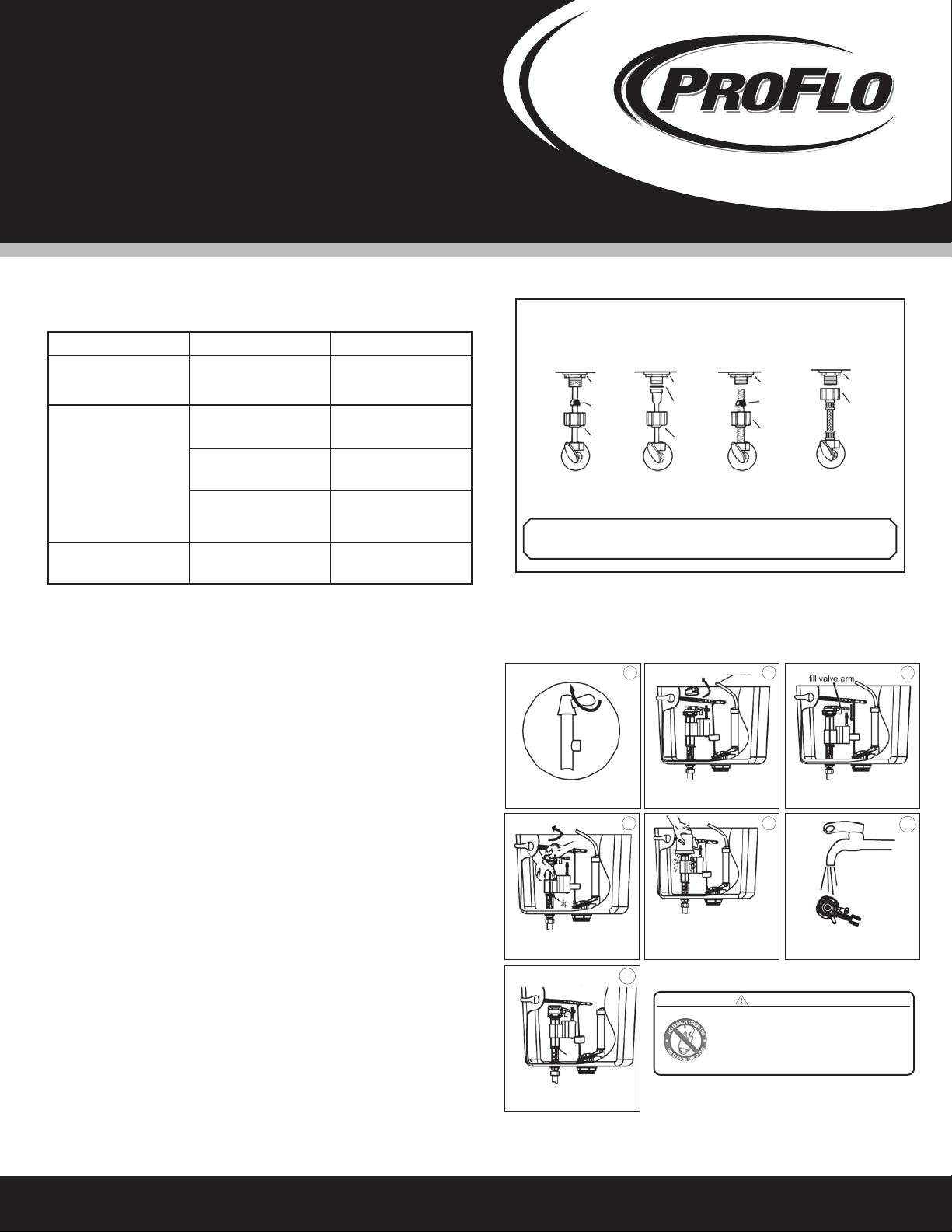
With the tapered side of the large rubber gasket facing
away from the tank, slip the rubber gasket over the
thread of the flushvalve on the bottom of the tank.
Connect the flexible water supply tube (Not Included)
onto the fill valve of the tank.
Set the tank onto the bowl,
with the tapered side of the
large rubber gasket towards
the bowl. While lowering the
tank onto the bowl, route
the flexible supply tube
through the opening provided.
9Fit the tapered side of the large rubber gasket into the
inlet opening of the bowl. The tank should sit level and
parallel to the finished wall.
Place the small rubber gaskets onto the tank mounting
bolts that were supplied with your tank. Slide both bolts
into the mounting holes from inside the tank.
Secure the tank by placing the metal washer and nut
onto the bottom of the tank bolts and tighten by hand
both nuts while holding the tank level.
With the tank level and sitting parallel to the wall, begin
to tight the nuts alternating between the two nuts to
keep the tank even. Tighten the nuts until the tank is
snug against the sanitary tank bar on the bowl.
CAUTION: PRODUCT IS FRAGILE
Do not over tighten nuts more than a snug fit.
Connect the flexible water supply line from the tank to
the shutoff valve. Tighten all coupling nuts securely.
Turn on water at the supply valve and allow the tank to fill.
Check all fittings for leakage and tighten any fittings that
are leaking.
10
Water
Supply
Opening
When performance matters.
WARNING: Do not use plumbers putty, pipe dope or any other sealant on the
water supply connections to this tank.
is void if any type of sealant is used on the water supply connection.WARRANTY
Note: If you wrench tighten the cap nut on mounting
stud #2 you will break the china since there is no
back nut on this stud.
.
WARNING
N
O
B
L
E
A
C
H
D
R
O
P
-
I
N
S
N
O
B
L
E
A
C
H
D
R
O
P
-
I
N
S
DO NOT USE IN-TANK TOILET BOWL CLEANERS
CONTAINING BLEACH OR CHLORINE
Result in Damage to tank components and may cause flooding
and property damage.
1.
2. Void Tynan Plumbing Fixtures Limited Warranty
Use of such products will:
ADVERTENCIA
EL PRODUCTO ES FRÁGIL.
Manéjese con cuidado para evitar
su ruptura y posibles daños.
Para la instalación en donde se considera
el cumplimiento con la ADA, la altura del
asiento debe ser de 17’’ y 19’’ (432mm
483mm) desde el piso terminado.
A
B
C
D
Recommended Tools & Materials
(A) Regular Screwdriver
(B) Adjustable Wrench
(C) Marker
(D) Tape Measure
(E) Level
(F) Silicone Sealant
(G) Putty Knife
(H) Flexible Supply Tube (Not Included)
(I) Closet Carrier/Support (Not Included)
CAUTION: PRODUCT IS FRAGILE
Handle with care to avoid breakage and possible injury!
When performance matters.
When performance matters.
Note: Views in this illustrations are for general representation
and may not necessarily define the exact contours of the product.
7730/7730HE
REV 10/2013
-1-
If you are installing the toilet on an existing support system,
make sure the system is in compliance with local code
requirements and the support system is weight rated for
the application requirements.
12
EG
F
If replacing an existing toilet be certain to shut off
water supply before removing old toilet.
SINK INSTALLATION:
34
Wall Hung Back Outlet Toilet with Tank Installation
For typical installation of the wall hung back outlet fixture, a
4-bolt Carrier/Support system, (not supplied with this unit)
must be used for attaching the water closet to the carrier/support
system and waste drain. Refer to the Installation Instructions
that were supplied with the Closet Carrier/Support System for
installation of the unit.
H
Place back up nuts supplied with the carrier/support on mounting
stud #1, #3 and #4. No back-up nut is used on mounting
stud #2! Adjust the two lower back-up nuts so the front face of
the nuts are 1/16”away from the finished wall. Using a level,
adjust the back-up nut on mounting stud #1 to a vertical plane
with mounting stud #3. Place back-up washer on the three
installed back-up nuts.
Note; If the wall is irregular, the three back-up nuts and
washers must be positioned to allow a minimum of 1/16”
gap between the fixture and the wall.
7-1/2”
(190mm)
9”(228mm)
I
Vista frontal Corte de los accesorios de montaje
For installations where consideration is given for
ADA compliance, the seat height must be 17”to
19”(432 to 483) from the finished floor.
Pernos de montaje N.º 1
vista de la pared terminada
Pernos de montaje N.º 2
Pernos de montaje N.º 3 Pernos de montaje N.º 4
Drenaje residual
pernos de
montaje
tuerca de
respaldo
tuerca de
respaldo
arandela de
fibra
tapa de la
tuerca
cabezal de
desague
5/16”
(8mm)
Mounting studs should extend 2-1/8”(54mm) beyond the
finished wall.
The waste horn should extend 5/16”(8mm) beyond the
finished wall.
pared terminada
vista superior
del transportador
A
B
C
D
Recommended Tools & Materials
(A) Regular Screwdriver
(B) Adjustable Wrench
(C) Marker
(D) Tape Measure
(E) Level
(F) Silicone Sealant
(G) Putty Knife
(H) Flexible Supply Tube (Not Included)
(I) Closet Carrier/Support (Not Included)
CAUTION: PRODUCT IS FRAGILE
Handle with care to avoid breakage and possible injury!
When performance matters.
When performance matters.
Note: Views in this illustrations are for general representation
and may not necessarily define the exact contours of the product.
7730/7730HE
REV 10/2013
-1-
If you are installing the toilet on an existing support system,
make sure the system is in compliance with local code
requirements and the support system is weight rated for
the application requirements.
12
EG
F
If replacing an existing toilet be certain to shut off
water supply before removing old toilet.
SINK INSTALLATION:
34
Wall Hung Back Outlet Toilet with Tank Installation
For typical installation of the wall hung back outlet fixture, a
4-bolt Carrier/Support system, (not supplied with this unit)
must be used for attaching the water closet to the carrier/support
system and waste drain. Refer to the Installation Instructions
that were supplied with the Closet Carrier/Support System for
installation of the unit.
H
Place back up nuts supplied with the carrier/support on mounting
stud #1, #3 and #4. No back-up nut is used on mounting
stud #2! Adjust the two lower back-up nuts so the front face of
the nuts are 1/16”away from the finished wall. Using a level,
adjust the back-up nut on mounting stud #1 to a vertical plane
with mounting stud #3. Place back-up washer on the three
installed back-up nuts.
Note; If the wall is irregular, the three back-up nuts and
washers must be positioned to allow a minimum of 1/16”
gap between the fixture and the wall.
7-1/2”
(190mm)
9”(228mm)
I
Vista frontal Corte de los accesorios de montaje
For installations where consideration is given for
ADA compliance, the seat height must be 17”to
19”(432 to 483) from the finished floor.
Pernos de montaje N.º 1
vista de la pared terminada
Pernos de montaje N.º 2
Pernos de montaje N.º 3 Pernos de montaje N.º 4
Drenaje residual
pernos de
montaje
2-1/8”
(54mm)
tuerca de
respaldo
tuerca de
respaldo
arandela de
fibra
tapa de la
tuerca
cabezal de
desague
5/16”
(8mm)
Mounting studs should extend 2-1/8”(54mm) beyond the
finished wall.
The waste horn should extend 5/16”(8mm) beyond the
finished wall.
pared terminada
vista superior
del transportador
empaque
de hule
pernos del
tanque
arandelas del
tanque
tuercas del tanque
-2-
Note: The back-up nuts, also referred to as the
bearing nuts, must be set to take the full loading
from the fixture while allowing a 1/6”clearance
between the fixture and the finished wall.
Follow the carrier manufacturer’s recommendation
settings for the outlet connection.
When setting fixture onto the carrier, it is not
recommended to use a wax ring, felt or neoprene
are recommended.
When setting the fixture to the carrier, the waste
gasket must be compressed sufficiently to assure
a positive gas and watertight seal.
56
78
Install the fiber washer and cap nut onto the mounting
stud #2, hand tighten until the nut and washer are
touching the china. Hand snug firmly the cap nut against
the china, this is all that is necessary for mounting the
cap nut and washer to stud #2.
.
Caulk sealant into the gap between the toilet and the
finished wall.
Using two people, install the bowl onto the fixture mounting
studs.
Place the fiber washer supplied with the carrier/support on
mounting studs #1, #3 and #4. (Do not place a fiber
washer or cap nut on mounting stud #2 at this time.)
Place the cap nut supplied with the carrier/support on
mounting studs #1, #3 and #4. While holding the bowl
level and using an adjustable wrench, tighten the three
cap nuts until they are snug.
CAUTION: PRODUCT IS FRAGILE
Do not over tighten nuts more than a snug fit.
With the tapered side of the large rubber gasket facing
away from the tank, slip the rubber gasket over the
thread of the flushvalve on the bottom of the tank.
Connect the flexible water supply tube (Not Included)
onto the fill valve of the tank.
9Fit the tapered side of the large rubber gasket into the
inlet opening of the bowl. The tank should sit level and
parallel to the finished wall.
Place the small rubber gaskets onto the tank mounting
bolts that were supplied with your tank. Slide both bolts
into the mounting holes from inside the tank.
Secure the tank by placing the metal washer and nut
onto the bottom of the tank bolts and tighten by hand
both nuts while holding the tank level.
With the tank level and sitting parallel to the wall, begin
to tight the nuts alternating between the two nuts to
keep the tank even. Tighten the nuts until the tank is
snug against the sanitary tank bar on the bowl.
CAUTION: PRODUCT IS FRAGILE
Do not over tighten nuts more than a snug fit.
Connect the flexible water supply line from the tank to
the shutoff valve. Tighten all coupling nuts securely.
Turn on water at the supply valve and allow the tank to fill.
Check all fittings for leakage and tighten any fittings that
are leaking.
10
apertura del
suministro de agua
When performance matters.
WARNING: Do not use plumbers putty, pipe dope or any other sealant on the
water supply connections to this tank.
is void if any type of sealant is used on the water supply connection.WARRANTY
Note: If you wrench tighten the cap nut on mounting
stud #2 you will break the china since there is no
back nut on this stud.
.
WARNING
N
O
B
L
E
A
C
H
D
R
O
P
-
I
N
S
N
O
B
L
E
A
C
H
D
R
O
P
-
I
N
S
DO NOT USE IN-TANK TOILET BOWL CLEANERS
CONTAINING BLEACH OR CHLORINE
Result in Damage to tank components and may cause flooding
and property damage.
1.
2. Void Tynan Plumbing Fixtures Limited Warranty
Use of such products will:
Instrucciones de instalación
Tanque con descarga
por gravedad
PF1705 / 1710 /
PF1705HE / PF1710HE
Distributed Exclusively by Ferguson and Wolseley Canada
© 2014 Ferguson Enterprises, Inc. 18218 04/14
A
B
C
D
Recommended Tools & Materials
(A) Regular Screwdriver
(B) Adjustable Wrench
(C) Marker
(D) Tape Measure
(E) Level
(F) Silicone Sealant
(G) Putty Knife
(H) Flexible Supply Tube (Not Included)
(I) Closet Carrier/Support (Not Included)
CAUTION: PRODUCT IS FRAGILE
Handle with care to avoid breakage and possible injury!
When performance matters.
When performance matters.
Note: Views in this illustrations are for general representation
and may not necessarily define the exact contours of the product.
7730/7730HE
REV 10/2013
-1-
If you are installing the toilet on an existing support system,
make sure the system is in compliance with local code
requirements and the support system is weight rated for
the application requirements.
12
EG
F
If replacing an existing toilet be certain to shut off
water supply before removing old toilet.
SINK INSTALLATION:
34
Wall Hung Back Outlet Toilet with Tank Installation
For typical installation of the wall hung back outlet fixture, a
4-bolt Carrier/Support system, (not supplied with this unit)
must be used for attaching the water closet to the carrier/support
system and waste drain. Refer to the Installation Instructions
that were supplied with the Closet Carrier/Support System for
installation of the unit.
H
Place back up nuts supplied with the carrier/support on mounting
stud #1, #3 and #4. No back-up nut is used on mounting
stud #2! Adjust the two lower back-up nuts so the front face of
the nuts are 1/16”away from the finished wall. Using a level,
adjust the back-up nut on mounting stud #1 to a vertical plane
with mounting stud #3. Place back-up washer on the three
installed back-up nuts.
Note; If the wall is irregular, the three back-up nuts and
washers must be positioned to allow a minimum of 1/16”
gap between the fixture and the wall.
7-1/2”
(190mm)
9”(228mm)
I
Vista frontal Corte de los accesorios de montaje
For installations where consideration is given for
ADA compliance, the seat height must be 17”to
19”(432 to 483) from the finished floor.
Pernos de montaje N.º 1
vista de la pared terminada
Pernos de montaje N.º 2
Pernos de montaje N.º 3 Pernos de montaje N.º 4
Drenaje residual
pernos de
montaje
2-1/8”
(54mm)
tuerca de
respaldo
tuerca de
respaldo
arandela de
fibra
tapa de la
tuerca
cabezal de
desague
5/16”
(8mm)
Mounting studs should extend 2-1/8”(54mm) beyond the
finished wall.
The waste horn should extend 5/16”(8mm) beyond the
finished wall.
pared terminada
vista superior
del transportador