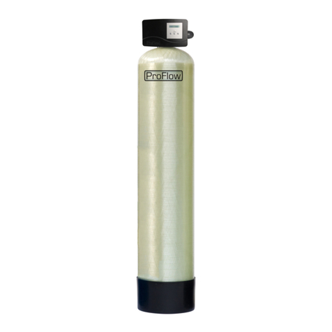
ProFlow PF-OXY1 Manual

© 2016erie watertreatment OM-PF-OXY-Rev2016.08
EN Installation & Operating Instructions
WATER
FILTER
-
Fe, Mn, H
2
S
FR Instructions d’Installation & Emploi
FILTRE Á EAU - Fe, Mn, H2S
DE Installation- & Gebrauchsanleitung
WASSER
FILTER
-
Fe, Mn, H
2
S
NL Installatie & Gebruiksinstructies
WATERFILTER - Fe, Mn, H2S
PL Instrukcja Instalacji i Eksploatacji
FILTR WODY
-
Fe, Mn, H
2
S
Models:
PF-OXY1
PF-OXY+1
PF-OXY1,5
PF-OXY+1,5

EN English........................................................................................................................ Page 3
FR Français......................................................................................................................Page 19
DE Deutsch......................................................................................................................Seite 35
NL Nederlands.................................................................................................................Pagina 51
PL Polski..........................................................................................................................Strona 67

TABLE OF CONTENT & INSTALLATION RECORD
Page 3 EN - English
Table of content & Installation record..................................................................................Page 3
Warning & Safety instructions..............................................................................................Page 4
Operating conditions & Requirements.................................................................................Page 5
Assembly..............................................................................................................................Page 7
Installation...........................................................................................................................Page 9
Commissioning.....................................................................................................................Page 10
Electronic control panel.......................................................................................................Page 11
Maintenance........................................................................................................................Page 14
Composition overview .........................................................................................................Page 15
Technical data - PF-OXY1 & PF-OXY+1...................................................................................Page 16
Technical data - PF-OXY1,5 & PF-OXY+1,5.............................................................................Page 17
For future reference, fill in the following data
INSTALLATION RECORD
Serial number: _______________________________________________
Model: _______________________________________________________
Water pressure-inlet: _______________________________________
Date of installation: _________________________________________
Company name: _____________________________________________
Installer name: ______________________________________________
Phone number: ______________________________________________
INSTALLATION RECORD
Serial number: _______________________________________________
Model: _______________________________________________________
Iron (Fe) content-inlet: _____________________________________
Manganese (Mn) content-inlet: ____________________________
Hydrogen Sulfide (H2S) content-inlet: _____________________
Water pressure-inlet: _______________________________________
Date of installation: _________________________________________
Company name: _____________________________________________
Installer name: ______________________________________________
Phone number: ______________________________________________

WARNING & SAFETY INSTRUCTIONS
EN - English Page 4
Before you begin the installation of the appliance, we advise you read
andcarefully follow the instructions contained in this manual. It contains
importantinformationaboutsafety,installation,useandmaintenance of
the product. The actual system that you have received, may differ from
the pictures/illustrations/descriptions in these Instructions.
Failure to follow the instructions could cause personal injury or damage
to the appliance or property. Only when installed, commissioned and
servicedcorrectly,theappliance willofferyou manyyearsoftrouble-free
operation.
The appliance is intended to ‘filter’ the water, meaning it will remove
specific undesired substances; it will not necessarily remove other
contaminants present in the water. The appliance will not purify polluted
water or make it safe to drink!
Installation of the appliance should only be undertaken by a competent
person, aware of the local codes in force. All plumbing and electrical
connections must be done in accordance with local codes.
Before setting up the appliance, make sure to check it for any externally
visible damage; do not install or use when damaged.
Use a hand truck to transport the appliance. To prevent accident or
injury, do not hoist the appliance over your shoulder. Do not lay the
appliance on its side.
Keep these Instructions in a safe place and ensure that new users are
familiar with the content.
The appliance is designed and manufactured in accordance with current
safety requirements and regulations. Incorrect repairs can result in
unforeseen danger for the user, for which the manufacturer cannot be
held responsible. Therefore repairs should only be undertaken by a
competent technician, familiar and trained for this product.
In respect of the environment, this appliance should be disposed of in
accordance with Waste Electrical and Electronic Equipment
requirements.Refertonational/locallawsandcodesforcorrectrecycling
of this appliance.

OPERATING CONDITIONS & REQUIREMENTS
Page 5 EN - English
APPLICATION LIMITATIONS PF-OXY:
pH: for Iron removal: 6,8 - 9,0
for Manganese removal: 8,0 - 9,0
for Iron & Manganese removal: 8,0 - 8,5
maximum contaminant content:
Iron (Fe2+) 15 mg/L
Manganese (Mn2+) 2 mg/L
Hydrogen Sulfide (H2S) 5 mg/L
organic matter: max. 4,0 mg/L; higher level may hinder the correct operation of
the system.
chlorine: max. 1,0 mg/L
iron bacteria: if iron bacteria are present, frequent service may be necessary,
while the life of the system may be limited; by properly controlling the iron
bacteria with chlorine or another approved method of bacterial reduction, the
system will function properly.
APPLICATION LIMITATIONS PF-OXY+:
pH: 5,8 - 10,5
maximum contaminant content:
Iron (Fe2+) 70 mg/L
Manganese (Mn2+) 35 mg/L
Hydrogen Sulfide (H2S) 15 mg/L
organic matter: water should be free from organic matter.
iron bacteria: if iron bacteria are present, frequent service may be necessary,
while the life of the system may be limited; by properly controlling the iron
bacteria with chlorine or another approved method of bacterial reduction, the
system will function properly.
OPERATING PRESSURE MIN-MAX: 2,5-8,0 bar / 36-116 psi
low operating pressure may lead to insufficient backwash of the filter media,
resulting in an increase in pressure drop and/or a reduction of the filtration
capacity during the service cycle.
if installed on a well, verify that the well pump is powerful enough to provide
sufficient flow rate for the backwash cycle.
check water pressure regularly.
takeintoaccountthatnighttimewaterpressuremaybeconsiderablyhigherthan
day time water pressure.
install a pressure reducer ahead of the appliance if necessary.
OPERATING TEMPERATURE MIN-MAX: 4-48 °C / 39-120 °F
donot installthe applianceinanenvironmentwhere highambient temperatures
(e.g. unvented boiler house) or freezing temperatures can occur.
the appliance cannot be exposed to outdoorelements, such as direct sunlight or
atmospheric precipitation.
do not install the appliance too close to a water heater; keep at least 3 m (10 ft)
of piping between the outlet of the appliance and the inlet of the water heater;

OPERATING CONDITIONS & REQUIREMENTS
EN - English Page 6
water heaters can sometimes transmit heat back down the cold pipe into the
appliance; always install a check valve at the outlet of the appliance.
ELECTRICAL CONNECTION:
this appliance only works on 24 VAC; always use it in combination with the
supplied transformer.
in case of damage to the power supply cable of the transformer, immediately
disconnectthe transformer fromthe power outlet and replacethe transformer.
make sure toplug the transformer intoa power outlet, which is
installed in a dry location, with the proper rating and over-
current protection.

ASSEMBLY
Page 7 EN - English
CONTENT CHECK
Actualpartsthatyouhave received, may differ from the
pictures/illustrations in these Instructions!
Only on systems with ≥3 cuft of filter media: for ease of
transportation and installation, the filter media is NOT
loaded in the pressure tank, but delivered in separate bags
of 1 cuft; it must be loaded on-site, after positioning of the
pressuretank.
Check the content of the system, using the Composition
Overview at the end of these Instructions. Identify and lay-
out the different components to facilitate the assembly.
SIMPLEX
Picture 1.a, 2.a, 3.a
A Simplex system consists of 1 single filter module (pressure
tank, filter media, control valve).
Duringnormaloperation,the system deliverstreatedwater.
As soon as it initiates a regeneration, it automatically goes
into bypass, guaranteeing uninterrupted supply of untreated
water.
It ispossibletoinstall asocalled NormallyOpen Service Valve
(e.g.asolenoidoperateddiaphragmvalve)intheoutletofthe
system, that is controlled by the electronic timer of the
system; this Service Valve will be activated during the entire
duration of the regeneration, to close-off the control valve's
standard 'untreated water bypass during regeneration'.
MULTIPLEX PARALLEL
Picture 4
A Multiplex PARALLEL system consists of 2 or more Simplex
systems, that:
-are hydraulically installedin parallel;
-are programmed for different times of regeneration;
-may have a so called Normally Open Service Valve (e.g. a
solenoid operated diaphragm valve) in the outlet of each
Simplex system, that is controlled by the electronic timer
of each Simplex system; this Service Valve will be
activated during the entire duration of the regeneration,
to close-off thecontrolvalve's standard 'untreated water
bypass during regeneration'.
During normal operation,all Simplex systems are in service,
doubling/tripling/… the service flow rate!
In case of a power failure, all Service Valves will be
deactivated, meaningthe outlet of allSimplexsystemswill be
open, guaranteeing uninterrupted supply of water.
FILTER MEDIA LOADING
1. Move the pressure tank to the correct installation
location; position it on a flat and level surface. Make sure
to leave enough space for ease of service.
2. Position the riser assembly upright and centred in the
pressure tank; plug the top of the riser tube with a piece
of tapeor cleanrag, toprevent filter media fromentering
the tube.
3. Place a funnel on the pressure tank opening and fill the
pressure tank with filter media; make sure the riser
assembly remains centered in the pressure tank.
4. Rinse the pressure tank opening to remove any grains of
filter media from the threaded section.
5. Unplug the top of the risertube.
CONTROL VALVE
only for PF-OXY1 & PF-OXY+1
1. Make sure the O-ring in the riser insert and the tank O-
ring(aroundthethreadedsectionofthecontrolvalve)are
in the correct position.
2. Screw the top distributor onto the control valve.
3. Lubricate the threaded section of the pressure tank, the
top of the riser tube and the tank O-ring of the control
valve; use a silicon-based lubricant.
4. Lowerthecontrolvalvestraightdownontotherisertube,
until the riser tube is correctly inserted in the riserinsert;
then push it down firmly and screw it onto the pressure
tank.
only for PF-OXY1,5 & PF-OXY+1,5
Picture 5
1. On the brass valve seat:
makesuretheO-ringintheriserinsertisinthecorrect
position;
install the top distributor and fix it by means of the 2
stainless steel screws;
install the tank O-ring in the groove on the flange
around the threaded section.
2. Lubricate the threaded section of the pressure tank, the
top ofthe risertube andthetank O-ring of thevalve seat;
use a silicon-based lubricant.
3. Lower the valve seat straight down onto the riser tube,
until the riser tube is correctly inserted in the riser insert
inside the valve seat; thenpush itdown firmly and screw
it onto the pressure tank.
4. Install the valve seat O-ring in the groove on the valve
seat.
5. Install the control valve onto the valve seat; mind the
alignment pin!
6. Bolt the control valve tothe valveseat bymeans of the 4
stainless steel bolts; tighten firmly.

ASSEMBLY
EN - English Page 8
AIR INJECTION SYSTEM
only for PF-OXY1 & PF-OXY+1
Picture 6.a
Make sure the air injection system is installed in vertical
position, with the check valve and air intake filter screen
pointing upwards. Rotate it to this position ifnecessary.
only for PF-OXY1,5 & PF- OXY+1,5
Picture 6.b
1. Install the air injection system on the control valve;
tighten the nut firmly by hand.

INSTALLATION
Page 9 EN - English
INLET & OUTLET
We strongly recommend the use of flexible hoses to
connect the appliance to the water distribution system; use
hoses with a large diameter in order to limit the pressure
loss.
We strongly recommend the installation of a bypass
system (not included with this product!) to isolate the
appliance from the water distribution system in case of
repairs.Itallowstoturnoffthewatertotheappliance,while
maintaining full-flow(untreated) water supply to theuser.
To prevent air from escaping from the compressed air
chamber, make sure the inlet line runs vertically upwards
into the water filter. If this is not possible, install a check
valve in the inlet line.
only for PF-OXY1 & PF-OXY+1:
with factory bypass (optional)
Picture 1
= mains water supply (untreated water)
= inlet of control valve (untreated water)
= outlet of control valve (treated water)
= application (treated water)
1. Screw the factory bypass onto the in/out ports on the
control valve (&); make sure to install the gasket
seals. Tighten the nuts firmly by hand.
2. Screw the connection kit with nuts onto the factory
bypass (&); make sure to install the gasket seals.
Tighten the nuts firmly by hand.
3. Connect the mains water supply to the adaptor on the
inlet port of the factory bypass ().
4. Connect the application to the adaptor onthe outlet port
of the factory bypass ().
only for PF-OXY1 & PF-OXY+1
with 3-valveconnection kit (not included)
Picture 2
= inlet of control valve (untreated water)
= outlet of control valve (treated water)
1. Install the 3-valve connection kit.
2. Screw the connection kit with nuts onto the in/out ports
on the control valve (&); make sure to install the
gasket seals. Tighten the nuts firmly by hand.
3. Connect the IN valve of the 3-valve connection kit to the
adaptor on the in port of the control valve ().
4. ConnecttheOUTvalveofthe3-valveconnectionkittothe
adaptor on the out port of the control valve ().
5. Connectthemainswatersupplytotheinletof the3-valve
connection kit.
6. Connect the application to the outlet of the 3-valve
connection kit.
only for PF-OXY1,5 & PF-OXY+1,5:
with 3-valveconnection kit (not incl.)
Picture 3
= inlet of control valve (untreated water)
= outlet of control valve (treated water)
1. Install the 3-valve connection kit.
2. Inserttheadaptorsinthein/outportsonthecontrolvalve
(&); make surenot todamagethe O-rings. Install the
nuts and tighten them firmly by hand.
3. Connect the IN valve of the 3-valve connection kit to the
adaptor on the in port of the control valve ().
4. ConnecttheOUTvalveofthe3-valveconnectionkittothe
adaptor on the out port of the control valve ().
5. Connectthemainswatersupplytotheinletofthe3-valve
connection kit.
6. Connect the application to the outlet of the 3-valve
connection kit.
DRAIN
We recommend the useof a stand pipe with airtrap.
To prevent backflow from the sewerage system into the
appliance, always install and use an air gap (included with
PF-OXY1 & PF-OXY1+), to connect the drain hose to the
sewerage system.
Lay-out the drain hose in such a way that pressure loss
is minimized; avoid kinks and unnecessary elevations.
Make sure that the sewerage system is suitable for the
rinse water flow rateof the appliance.
only for PF-OXY1 & PF-OXY+1
Picture 7
1. Install the air gap to the sewerage system; it fits over a
32 mm pipe or inside a 40 mm pipe adaptor. Ensure a
permanent and watertight connection.
2. Connect a 13 mm hose to the drain connection of the
control valve (); secure it by means of a clamp.
3. Run the drain hose to the airgap and connect it to one of
the hose barbs; secure it by means of a clamp. This drain
lineoperatesunderpressure,soitmaybeinstalledhigher
than the appliance.
only for PF-OXY1,5 & PF-OXY+1,5
Picture 8
1. Connectapipetothe1”BSPMaledrainconnectionofthe
control valve ();use an appropriate sealant.
2. Run the pipe to the sewerage system and connect it,
ensuring sufficient air gap between the end of the pipe
and the sewerage system. This drain line operates under
pressure,soit may be installed higherthan the appliance.
SERVICE VALVE (optional)
Picture 9
1. Plug the DIN plug on the connection cable of the Service
Valve into the DIN socket at the back of the electronic
timer head of the control valve ().

COMMISSIONING
EN - English Page 10
ELECTRICAL
1. Connect the appliances power cord to the transformers
output.
2. Plug the transformer into an electrical outlet.
PRESSURIZING
1. Put the bypass system in 'bypass' position.
2. Make sure the electronic controller of the appliance is in
service mode.
3. Open the mains water supply.
4. Open a cold treated water faucet nearby the appliance
and let the water run for a few minutes until all air is
purged and all foreign material that may have resulted
from the installation is washed out; close the tap.
5. Gently pressurizethe appliance,by putting it intoservice:
close the 'BYPASS' valve;
open the 'OUT' valve;
slowly open the 'IN' valve.
6. After 2-3 minutes, open a cold treated water faucet
nearby the appliance and let the water run for a few
minutesuntilallairispurgedfromtheinstallationandthe
filter media is rinsed (it is normal for the rinse water to
show some discoloration!); let the water run until the
rinse water is clear; close the tap.
7. Check the appliance and all hydraulic connections for
leaks.
During the passage through the compressed air
chamber,the treated water will gethighlyoxygenated. As a
consequence it may becomeslightly non-transparent (milky
appearance) when it flows from the tap into a glass. This is
totallyharmlessfor the quality ofthe treated waterand will
disappear rapidly if the water is left standing for a moment!
ELECTRONIC CONTROL PANEL
1. Program the electronic controller.
INITIATE A REGENERATION
We strongly recommend to postpone the execution of
this 'start-up' regeneration by 24 hours. The filter media
needs sufficient time to absorb water and reach its normal
service weight. If the regeneration is performed too soon,
the filter media may be pushed against the top distributor
duringthe backwash cycle,possiblyresulting in loss of filter
mediaor damage to the top distributor.
1. Manually initiate a regeneration, by pressing the scroll
button repeatedly until the display shows:
2. Leave the appliance in this position; the count-down
timer will count down to 0 sec and start a regeneration.
Regen in 10 sec

ELECTRONIC CONTROL PANEL
Page 11 EN - English
Picture 10
symbol
button
function
SCROLL
to advance to the next
parameter
UP
to increase the value of the
parameter
DOWN
to decrease the value of the
parameter
POWER-UP
After power-up the display will show the installed software
version. After 5 seconds it will automatically revert back to
the service display.
POWER FAILURE
In the event of a power failure, the program will remain
stored in theNOVRAM®duringan undefined period, while an
incorporated SuperCap will maintain the correct time of day
during a period of several hours; consequently, in case of
prolonged power failure, the time of day might not be
maintained; if this happens, the time of day will be reset to
8:00 when the power supply is re-established, while the
indication will flash, indicating that the time of day needs to
be set.
When the power failure occurs during the execution of an
automatic regeneration, the control valve will remain in its
last position; when the power supply is re-established, the
control valve will return tothe service position, stay there for
60 sec. and restart a complete regeneration from the
beginning.
TIMER FAILURE
In the event of a timer failure, the display will show the
message:
If powering off/on the appliance doesn’t solve this problem,
professional service is required.
SERVICE MODE
In service mode the display shows the time of day and the
number of days remaining until the next regeneration:
REGENERATION MODE
In regeneration mode the display shows the remaining
regeneration time and the remaining cycle time:
The control valvecanbe reset to service modeat anytime by
pressing the scroll button, as such manually advancing it
through the regeneration cycles.
MANUAL REGENERATION
It is possible to manually initiate a regeneration.
1. Press the scroll button repeatedly until the display
shows:
If the control valve is left in this position, the count-
down timer will count down to 0 sec and start a
regeneration.
To cancel this mode, press the scroll button before
the countdown timer has reached 0 sec; the control
valve will return to the service mode.
2. Press the scroll button again if you want to manually
advance the control valve to the next regeneration cycle.
DRIVE MOTOR SPEED
(only for PF-OXY1 & PF-OXY+1)
The drive motor of the control valve, that drives the valve
body to its different regeneration positions, will start-up at
low speed to reduce its noise level. To increase the speed of
the drive motor, simply press the scroll button as soon as
the drive motor is activated.
Service Required
Regen in 10 sec
8:01 4 DAY REM
Rgn:123 CycY:456

ELECTRONIC CONTROL PANEL
EN - English Page 12
PROGRAMMING INSTRUCTIONS -
BASIC SETTINGS
Beforeenteringtheprogrammingmode,makesurethat
the appliance is in the service mode.
1. Press the scroll button; the display will show:
Press the up or down button to set the
language.
2. Press the scroll button again; the display will show:
Press the up button or down button to set the
time of day.
3. Press the scroll button again; the display will show:
Press the up ordown button to set the number
of days between regenerations.
The filtration capacity of the appliance mainly depends
on the daily water usage and the Iron/Manganese content
in the water; many otherfactors mayalso havea significant
impact on the filtration capacity. Therefore it is
recommendedtoregeneratetheapplianceonaregulartime
basis. In most applications a regeneration every 4 days
should besufficient.
In case of extreme iron/manganese content and/or
water consumption, it is recommended to lower the
regeneration interval to 1 or max. 2 days.
Language:English
Set time: 8:01
Interval:4 Days

ELECTRONIC CONTROL PANEL
Page 13 EN - English
PROGRAMMING INSTRUCTIONS -
CONFIGURATION PARAMETERS
Beforeenteringtheprogrammingmode,makesurethat
the appliance is in the service mode.
All configuration parameters on this appliance have
been pre-programmed in the factory, to offer optimal
performance in a wide range of applications and situations.
Neverthelessitmaybenecessaryordesirableto changeany
of these parameters, to further optimize the appliances
performance or to adapt it to the specific requirements of
the installation.
1. Press the scroll button and hold it for 5 sec until the
displayshows:
2. Within 10 sec, press the up button; the display will
show:
Press the up or down button to set the length
of the regeneration cycle.
Pressthescrollbuttonagaintoadvancetothenext
regeneration cycle.
Cycle 1
Backwash
Cycle 2
Air intake
Cycle 3
Fast rinse
Cycle 4
No function (PF
-
OXY1,5
& PF
-
OXY1,5
+
)
3. Press the scroll button again; the display will show:
Press the up or down button to set the time of
regeneration.
4. Press the scroll button again; the display will show:
Press the up or down button to save the
program into the NOVRAM® and exit the
programming level.
Cycle 1: XX min
System Check
Regen @ 0:00
Exit

MAINTENANCE
EN - English Page 14
ROUTINE CHECKS
Regularlytheusershouldperformabasicchecktoverifyifthe
appliance is functioning correctly, on the basis of the
following control points:
1. Check settings of electronic control panel.
2. Check water compositionbefore/after appliance.
3. Check drain line from control valve; there shouldn’t be
any water flow(unless appliance is in regeneration).

4. Checkapplianceandsurroundingarea;thereshouldn’tbe
any water leakages.
BYPASSING THE APPLIANCE
Occasionally it may be necessary to put the appliance
hydraulically in bypass, i.e. to isolate it from the water
distribution system; f.e.:
in case of an urgent technical problem;
when it is not necessary to supply treated water to the
application.
WITH FACTORY BYPASS (optional) (only for PF-OXY1 & PF-
OXY+1)
Picture 11.a
SERVICE POSITION
= inlet valve to appliance is OPEN
= outlet valve from appliance is OPEN
Picture 11.b
BYPASSPOSITION
= inlet valve to appliance is CLOSED
= outlet valve from appliance is CLOSED
Picture 11.c
MAINTENANCE POSITION
= inlet valve to appliance is OPEN
= outlet valve from appliance is CLOSED
SANITIZING THE APPLIANCE
This appliance is manufactured from premium quality
material and assembled in safeconditions to assure it is clean
and sanitary. If installed andserviced correctly,this appliance
willnotinfectorcontaminateyourwatersupply.However,as
in any 'device' plumbed-in in your water distribution system,
a proliferation of bacteria is possible, especially in case of
'stagnant water'. Therefore this appliance will automatically
rinse the filter media periodically.
If the power supply to the appliance is disconnected for a
longer period of time, we recommend, when the power
supply is re-established, to manually initiate a complete
regeneration.

COMPOSITION OVERVIEW
Page 15 EN - English
Model Media
volume PN Control valve, incl. transformer,
1” male BSP connections Pressure tank,
incl. distributor assy Underbedding Filter media
(1 cuft bag)
cuft model # model # type ltr type #
PF-OXY1
1 35669 2400TF/J5N/SV/AIR 1 10x40 1 Gravel 2-4 mm 4 Birm 1
2 35670 2400TF/J5Q/SV/AIR 1 12x52 1 Gravel 2-4 mm 6 Birm 2
3 35708 2400TF/J5S/SV/AIR 1 14x65 1 Gravel 2-4 mm 8 Birm 3
PF-OXY+1
1 35781 2400TF/J5N/SV/AIR 1 10x40 1 Gravel 2-4 mm 4 Katalox-Light 1
2 35782 2400TF/J5Q/SV/AIR 1 12x52 1 Gravel 2-4 mm 6 Katalox-Light 2
3 35783 2400TF/J5S/SV/AIR 1 14x65 1 Gravel 2-4 mm 8 Katalox-Light 3
Model Media
volume PN Control valve, incl. transformer,
1,5” male BSP connections Pressure tank,
incl. distributor assy Underbedding Filter media
(1 cuft bag)
cuft model # model # type ltr type #
PF-OXY1,5
3 35862 EV1.5TF/J/100/AIR 1 14x65 1 Gravel 2-4 mm 12 Birm 3
4 35863 EV1.5TF/J/150/AIR 1 16x65 1 Gravel 2-4 mm 15 Birm 4
5 35864 EV1.5TF/J/200/AIR 1 18x65 1 Gravel 2-4 mm 18 Birm 5
7 35865 EV1.5TF/J/250/AIR 1 21x62 1 Gravel 2-4 mm 22 Birm 7
10 35866 EV1.5TF/J/350/AIR 1 24x72 1 Gravel 2-4 mm 26 Birm 10
PF-OXY+1,5
1 35874 EV1.5TF/J/100/AIR 1 14x65 1 Gravel 2-4 mm 12 Katalox-Light 3
4 35875 EV1.5TF/J/150/AIR 1 16x65 1 Gravel 2-4 mm 15 Katalox-Light 4
5 35876 EV1.5TF/J/200/AIR 1 18x65 1 Gravel 2-4 mm 18 Katalox-Light 5
7 35877 EV1.5TF/J/250/AIR 1 21x62 1 Gravel 2-4 mm 22 Katalox-Light 7
10 35878 EV1.5TF/J/350/AIR 1 24x72 1 Gravel 2-4 mm 26 Katalox-Light 10

TECHNICAL DATA - PF-OXY1 -& OXY+1
EN - English Page 16
Technical specifications:
Model PF-OXY1 / PF-OXY+1
Filter media (cuft) 1 2 3
Operating pressure min/max (bar) 2,5/8,3
Operating temperature min/max (°C) 4/48
Electrical connection (V/Hz) 230/50(1)
Max. power consumption(VA) 12
Hydraulic connection inlet/outlet 1” BSP Male
Hydraulic connection drain 13 mm hose barb
Pressuretank 10x40 12x52 14x65
(1) Supplied with 24V transformer
Performances @ 3 bar operating pressure(2):
Model PF-OXY1
Filter media (cuft) 1 2 3
Service flow rate @∆p 1 bar (m³/hr)(3) 3,4 3,4 3,5
Recomm. max. service flow(m³/hr) (4) 1,0 1,5 2,0
Rinse water usage per regeneration (ltr) 290 413 536
Backwash flow rate(ltr/min) 23 31 38
Model PF-OXY+1
Filter media (cuft) 1 2 3
Service flow rate @∆p 1 bar (m³/hr)(3) 3,4 3,4 3,5
Recomm. max. service flow (m³/hr) (4) 1,5 2,2 3,0
Rinse water usage per regeneration (ltr) 290 413 536
Backwash flow rate(ltr/min) 23 31 38
(2) Indicative numbers, performances depending on operating conditions and water quality
(3) Based on clean filter bed operation
(4) Flow rate at which filtration process is still executed adequately,higher intermittent flow rates arepossible
Dimensions:
Model PF-OXY1 / PF-OXY+1
Filter media (cuft) 1 2 3
Width(mm)(W) 264 311 365
Depth (mm) (D) 282 311 365
Depth,incl. factorybypass(mm)(D) 371 376 403
Height(mm)(H) 1.182 1.500 1.836

TECHNICAL DATA - PF-OXY1,5 -& OXY+1,5
Page 17 EN - English
Technical specifications:
Model PF-OXY1,5 / PF-OXY+1,5
Filter media (cuft) 3 4 5 7 10
Operating pressure min/max (bar) 2,5/8,0
Operating temperature min/max (°C) 4/48
Electrical connection (V/Hz) 230/50(1)
Max. pow
er consumption(VA)
80
Hydraulic connection inlet/outlet 1,5” BSP Male
Hydraulic connection drain 1” BSP Male
Pressuretank 14x65 16x65 18x65 21x62 24x72
(1) Supplied with 24V transformer
Performances @ 3 bar operating pressure(2):
Model PF-OXY1,5
Filter media (cuft) 3 4 5 7 10
Service flow rate @∆p 1 bar (m³/hr)(3) 7,8 7,8 7,8 7,9 8,0
Recomm. max. service flow(m³/hr) (4) 2,0 2,7 3,4 4,1 6,0
Rinse water usage per regeneration (ltr) 556 811 1.065 1.366 1.922
Backwash flow rate(ltr/min) 38 57 76 95 133
Model PF-OXY+1,5
Filter media (cuft) 3 4 5 7 10
Service flow rate @∆p 1 bar (m³/hr)(3) 7,8 7,8 7,8 7,9 8,0
Recomm. max. service flow (m³/hr) (4) 3,0 3,9 4,9 6,7 8,8
Rinse water usage per regeneration (ltr) 556 811 1.065 1.366 1.922
Backwash flow rate(ltr/min) 38 57 76 95 133
(2) Indicative numbers, performances depending on operating conditions and water quality
(3) Based on clean filter bed operation
(4) Flow rate at which filtration process is still executed adequately, higher intermittent flow rates are possible
Dimensions:
Model PF-OXY1,5 / PF-OXY+1,5
Filter media (cuft) 3 4 5 7 10
Width(mm)(W) 408 434 491 555 635
Depth (mm) (D) 408 434 491 555 635
Height(mm)(H) 1.955 1.952 2.003 2.002 2.199

EN - English Page 18

TABLE DES MATIÈRES & DONNÉES D’INSTALLATION
Page 19 FR - Français
Table des matières & Données d’installation........................................................................Page 19
Mesures de précaution & Consignes de sécurité..................................................................Page 20
Conditions de fonctionnement & Exigences.........................................................................Page 21
Assemblage..........................................................................................................................Page 23
Installation...........................................................................................................................Page 25
Mise en marche...................................................................................................................Page 27
Panneau de commande électronique...................................................................................Page 28
Entretien..............................................................................................................................Page 31
Liste de composition............................................................................................................Page 32
Données techniques - PF-OXY1 & PF-OXY+1 .........................................................................Page 33
Données techniques - PF-OXY1,5 & PF-OXY+1,5....................................................................Page 34
Pour future référence, notez les données suivantes
DONNÉES D’INSTALLATION
Numéro de série: ____________________________________________
Modèle: ______________________________________________________
Teneur en Fer (Fe)-entrée: _________________________________
Teneur en Manganèse (Mn)-entrée: _______________________
Teneur en H2S-entrée : _____________________________________
Pression d’eau-entrée: ______________________________________
Date d’installation: __________________________________________
Nom société: ________________________________________________
Nom installeur: ______________________________________________
Numéro de Tél.: _____________________________________________

MESURES DE PRÉCAUTION & CONSIGNES DE SÉCURITÉ
FR - Français Page 20
Avantd’entamer l’installationdel’appareil,nousvousrecommandonsde
lire et suivre attentivement les instructions dans ce manuel. Il contient
des informations importantes concernant la sécurité, l’installation,
l’usage et l’entretien du produit. L’appareil que vous avez reçu peut
différer des photos/illustrations/descriptions dans ces Instructions.
Ne pas suivre les instructions du manuel peut causer des blessures
personnelles et/ou endommager le produit. Seulement s’il est installé,
mis en route et entretenu de manière correcte, l’appareil vous offrira de
pleines années de service exempt de pannes.
L’appareil est destiné à 'filtrer' l’eau, c’est à dire il enlèvera des
substances indésirables spécifiques; il n’enlèvera pas nécessairement
d’autres contaminants présents dans l’eau. L’appareil ne rendra pas de
l’eau polluée pure ni potable!
L’installation de l’appareil doit être effectuée par une personne
compétente, au courant des codes locaux en vigueur. Tous les
raccordements hydrauliques et électriques doivent être réalisés en
concordance aux codes locaux.
Avantd’installer l’appareil, veuillez inspecter l’appareil pourcontrôler s’il
n’y a pas de dommages visibles; n’installez pas l’appareil s’il est
endommagé.
Utiliser une charrette pour transporter l’appareil. Afin d’éviter tout
accident ou blessure,ne hisser pas l’appareilsurvotre épaule. Nemettez
pas l’appareil sur son côté.
Conservez ces Instructions dans un endroit sûr et veillez à informer de
nouveaux utilisateurs de son contenu.
L’appareil est dessiné et fabriqué en concordance aux consignes de
sécurité et régulations actuelles. Des réparations incorrectes peuvent
mettreenpérillematérieldel’utilisateur,pourlequellefabricantnepeut
pas être rendu responsable. Pour cette raison toute réparation ne peut
être effectuée que par un technicien compétent et formé pour ce
produit.
En respect de l’environnement, cet appareil devrait être recyclé en
concordance à la loi Déchets d’Equipements Électriques et Électroniques
(DEEE). Vérifier les lois et codes nationaux/locaux pour le recyclage
correct de cet appareil.
Other manuals for PF-OXY1
1
This manual suits for next models
2
Table of contents
Languages:
Other ProFlow Water Filtration System manuals
Popular Water Filtration System manuals by other brands

Oxyline
Oxyline X701 A1 quick start guide

Watts
Watts OneFlow OF140-4 Installation, operation and maintenance manual

Graco
Graco 213-062 instructions

Magus
Magus BASIKA rho NS 2 Installation, operating and maintenance instructions

EINHELL
EINHELL 12 L Original operating instructions

GR
GR AKF 300 Operation manual

North Star
North Star NSAS 2500 Installation

Blastrac
Blastrac BDS-66 operating manual

AmeriFlow Water Systems Inc.
AmeriFlow Water Systems Inc. ET6500 owner's manual

Pentair
Pentair INTELLICHLOR COMSYS-12 installation guide

AquaScape
AquaScape 77011 installation instructions

Pentair
Pentair FLECK 9000 SXT Installer manual