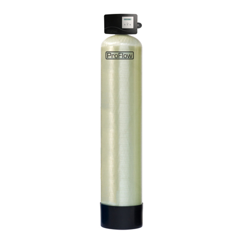
ProFlow PF-PHN Manual

© 2018 erie water treatment OM-PF-PHN-Rev2018.01
EN
Installation & Operating Instructions
WATER FILTER - pH correction
FR
Instructions d’Installation & Emploi
FILTRE D’EAU - correction pH
DE
Installation- & Gebrauchsanleitung
WASSERFILTER - pH Korrektur
NL
Installatie & Gebruiksinstructies
WATERFILTER - pH correctie
Models:
PF-PHN

EN English .............................................................................................................................Page 3
FR Français ...........................................................................................................................Page 15
DE Deutsch ...........................................................................................................................Seite 27
NL Nederlands......................................................................................................................Pagina 39

TABLE OF CONTENT & INSTALLATION RECORD
Page 3 EN - English
Table of content & Installation record.....................................................................................Page 3
Warning & Safety instructions .................................................................................................Page 4
Operating conditions & Requirements ....................................................................................Page 5
Installation ...............................................................................................................................Page 6
Commissioning.........................................................................................................................Page 7
Electronic control panel ...........................................................................................................Page 8
Maintenance ............................................................................................................................Page 11
Technical data ..........................................................................................................................Page 13
For future reference, fill in the following data
INSTALLATION RECORD
Serial number: _______________________________________________
Model: ________________________________________________________
pH inlet: _______________________________________________________
Water pressure-inlet: ________________________________________
Date of installation: __________________________________________
Company name: ______________________________________________
Installer name: _______________________________________________
Phone number: ______________________________________________

WARNING & SAFETY INSTRUCTIONS
EN - English Page 4
•Before you begin the installation of the appliance, we advise you read
and carefully follow the instructions contained in this manual. It contains
important information about safety, installation, use and maintenance of
the product. The actual system that you have received, may differ from
the pictures/illustrations/descriptions in these Instructions.
•Failure to follow the instructions could cause personal injury or damage
to the appliance or property. Only when installed, commissioned and
serviced correctly, the appliance will offer you many years of trouble-free
operation.
•The appliance is intended to improve certain parameters of the water.
The appliance will not purify polluted water or make it safe to drink!
•Installation of the appliance should only be undertaken by a competent
person, aware of the local codes in force. All plumbing and electrical
connections must be done in accordance with local codes.
•Before setting up the appliance, make sure to check it for any externally
visible damage; do not install or use when damaged.
•Use a hand truck to transport the appliance. To prevent accident or
injury, do not hoist the appliance over your shoulder. Do not lay the
appliance on its side.
•Keep these Instructions in a safe place and ensure that new users are
familiar with the content.
•The appliance is designed and manufactured in accordance with current
safety requirements and regulations. Incorrect repairs can result in
unforeseen danger for the user, for which the manufacturer cannot be
held responsible. Therefore repairs should only be undertaken by a
competent technician, familiar and trained for this product.
•In respect of the environment, this appliance should be disposed of in
accordance with Waste Electrical and Electronic Equipment
requirements. Refer to national/local laws and codes for correct recycling
of this appliance.

OPERATING CONDITIONS & REQUIREMENTS
Page 5 EN - English
•APPLICATION LIMITATIONS:
incoming pH: pHneutralizer: 6,0 - 7,0
pHneutralizerXL: 5,0 - 6,0
If the pH of the incoming water is below the stated levels, insufficient
correction of the pH may occur, i.e. the pH at the outlet of the appliance may
not be raised as expected.
incoming hardness: max. 100 mg/L as CaCO3(= 10 °f or 5,6 °dH); at higher
hardness levels the appliance will still function, but the filter media will
become ‘caked’, reducing its lifespan; increasing the regeneration frequency
(i.e. reducing the number of days between 2 regenerations) may prevent this
from happening.
outgoing hardness: as a result of the dissolution of the filter media, the water
hardness at the outlet of the aplliance will increase; a water softener may
become necessary.
•OPERATING PRESSURE MIN-MAX: 2,0-8,0 bar / 29-116 psi
low operating pressure may lead to insufficient backwash of the filter media,
resulting in an increase in pressure drop and/or a reduction of the filtration
capacity during the service cycle.
if installed on a well, verify that the well pump is powerful enough to provide
sufficient flow rate for the backwash cycle.
check water pressure regularly; it may fluctuate severely depending on the
time of day, the day of the week or even the season of the year.
take into account that night time water pressure may be considerably higher
than day time water pressure.
install a pressure reducer ahead of the appliance if necessary.
install a pressure booster, if it is likely that water pressure may drop below the
minimum.
•OPERATING TEMPERATURE MIN-MAX: 4-38 °C / 39-100 °F
do not install the appliance in an environment where high ambient
temperatures (e.g. unvented boiler house) or freezing temperatures can
occur.
the appliance cannot be exposed to outdoor elements, such as direct
sunlight or atmospheric precipitation.
do not install the appliance too close to a water heater; keep at least 3 m (10
ft) of piping between the outlet of the appliance and the inlet of the water
heater; water heaters can sometimes transmit heat back down the cold pipe
into the appliance; always install a check valve at the outlet of the appliance.
•ELECTRICAL CONNECTION:
this appliance only works on 24 VDC; always use it in combination with the
supplied transformer.
in case of damage to the power supply cable of the transformer, immediately
disconnect the transformer from the power outlet and replace the
transformer.
make sure to plug the transformer into a power outlet, which is installed in a
dry location, with the proper rating and over-current protection.

INSTALLATION
EN - English Page 6
INLET & OUTLET
We strongly recommend the use of flexible hoses to
connect the appliance to the water distribution system; use
hoses with a large diameter in order to limit the pressure
loss.
We strongly recommend the installation of a bypass
system (not included with this product!) to isolate the
appliance from the water distribution system in case of
repairs. It allows to turn off the water to the appliance, while
maintaining full-flow (untreated) water supply to the user.
with factory bypass (optional)
Picture 1
= mains water supply (untreated water)
❖= inlet of control valve (untreated water)
= outlet of control valve (treated water)
= application (treated water)
1. Screw the factory bypass onto the in/out ports on the
control valve (❖&); make sure to install the gasket
seals. Tighten the nuts firmly by hand.
2. Screw the connection kit with nuts onto the factory
bypass (&); make sure to install the gasket seals.
Tighten the nuts firmly by hand.
3. Connect the mains water supply to the adaptor on the
inlet port of the factory bypass ().
4. Connect the application to the adaptor on the outlet port
of the factory bypass ().
with 3-valve connection kit (not included)
Picture 2
= inlet of control valve (untreated water)
❖= outlet of control valve (treated water)
1. Install the 3-valve connection kit.
2. Screw the connection kit with nuts onto the in/out ports
on the control valve (&❖); make sure to install the
gasket seals. Tighten the nuts firmly by hand.
3. Connect the IN valve of the 3-valve connection kit to the
adaptor on the in port of the control valve ().
4. Connect the OUT valve of the 3-valve connection kit to the
adaptor on the out port of the control valve (❖).
5. Connect the mains water supply to the inlet of the 3-valve
connection kit.
6. Connect the application to the outlet of the 3-valve
connection kit.
DRAIN
We recommend the use of a stand pipe with P-trap.
To prevent backflow from the sewerage system into the
appliance, always ensure sufficient air gap between the end
of the drain hose or pipe and the sewerage system.
Lay-out the drain hose in such a way that pressure loss
is minimized; avoid kinks and unnecessary elevations.
Make sure that the sewerage system is suitable for the
rinse water flow rate of the appliance.
Picture 3
1. Connect the 19 mm hose to the drain connection of the
control valve (); secure it by means of the clamp.
2. Run the drain hose to the sewerage system and connect
it, ensuring sufficient air gap between the end of the hose
and the sewerage system. This drain line operates under
pressure, so it may be installed higher than the appliance.

COMMISSIONING
Page 7 EN - English
ELECTRICAL
1. Connect the appliances power cord to the transformers
output.
2. Plug the transformer into an electrical outlet.
PRESSURIZING
1. Put the bypass system in 'bypass' position.
2. Make sure the electronic controller of the appliance is in
service mode.
3. Open the mains water supply.
4. Open a cold treated water faucet nearby the appliance
and let the water run for a few minutes until all air is
purged and all foreign material that may have resulted
from the installation is washed out; close the tap.
5. Gently pressurize the appliance, by putting it into service:
•close the 'BYPASS' valve;
•open the 'OUT' valve;
•slowly open the 'IN' valve.
6. After 2-3 minutes, open a cold treated water faucet
nearby the appliance and let the water run for a few
minutes until all air is purged from the installation and the
filter media is rinsed (it is normal for the rinse water to
show some discoloration!); let the water run until the
rinse water is clear; close the tap.
7. Check the appliance and all hydraulic connections for
leaks.
ELECTRONIC CONTROL PANEL
1. Program the electronic controller.
INITIATE A REGENERATION
1. Manually initiate a regeneration, by pressing the scroll
button repeatedly until the display shows:
2. Leave the appliance in this position; the count-down
timer will count down to 0 sec and start a regeneration.
Regen in 10 sec

ELECTRONIC CONTROL PANEL
EN - English Page 8
Picture 4
symbol
button
function
SCROLL
to advance to the next
parameter
UP
to increase the value of the
parameter
DOWN
to decrease the value of the
parameter
POWER-UP
After power-up the display will show the installed software
version for a period of 5 seconds.
POWER FAILURE
In the event of a power failure, the program will remain
stored in the NOVRAM® during an undefined period, while an
incorporated SuperCap will maintain the correct time of day
during a period of several hours; consequently, in case of
prolonged power failure, the time of day might not be
maintained; if this happens, the time of day will be reset to
8:00 when the power supply is re-established, while the
indication will flash, indicating that the time of day needs to
be set.
When the power failure occurs during the execution of an
automatic regeneration, the control valve will remain in its
last position; when the power supply is re-established, the
control valve will return to the service position, stay there for
60 sec. and restart a complete regeneration from the
beginning.
TIMER FAILURE
In the event of a timer failure, the display will show the
message:
The buzzer, if enabled (see Basic Settings), will beep
continuously. If powering off/on the appliance doesn’t solve
this problem, professional service is required.
MAINTENANCE REMINDER
Only available if the maintenance reminder function has
been activated and programmed by your supplier!
Once the maintenance interval is reached, the following will
happen:
1. the display will intermittently show the message:
2. the buzzer, if enabled (see Basic Settings), will beep 3
times every hour.
While the appliance will continue to operate normally, it is
recommended to have preventive maintenance performed
by a professional.
To reset the maintenance reminder, simply access the
configuration parameters programming mode.
SERVICE MODE
In service mode the display shows the time of day and the
number of days remaining until the next regeneration:
REGENERATION MODE
In regeneration mode the display shows the remaining
regeneration time and the remaining cycle time:
The appliance can be reset to service mode at any time by
pressing the scroll button, as such manually advancing it
through the regeneration cycles.
MANUAL REGENERATION
It is possible to manually initiate an immediate regeneration
or a delayed regeneration (at the preprogrammed time of
regeneration).
1. Press the scroll button; the display will show:
•If the control panel is left in this position, the
countdown timer will countdown to 0 sec and start an
immediate regeneration.
•To cancel this mode, press the scroll button before
the countdown timer has reached 0 sec; the display
will show:
•If the control panel is left in this position, a delayed
regeneration will be started at the indicated
preprogrammed time of regeneration.
•To cancel this mode, press the scroll button; the
control panel will return to the service mode.
HOLIDAY MODE
It is possible to put the appliance in holiday mode; this will
prevent automatic regeneration from taking place, yet will
ensure the appliance is automatically regenerated at the end
of the holiday cycle.
Service Required
8:01 7 DAY REM
Maintenance Now
Rgn:XXX CycY:ZZZ
Regen in 10 sec
Regen @ 2:00
8:01 7 DAY REM

ELECTRONIC CONTROL PANEL
Page 9 EN - English
1. Press the scroll button repeatedly until the display
shows:
•
•Press the up or down button to activate the
holiday mode by setting the number of full days away
from home,or deactivate the holiday mode (OFF).
Once the control panel is back in service mode, the display
will show:
The holiday mode is automatically cancelled when a
regeneration is manually initiated!
PROGRAMMING INSTRUCTIONS -
BASIC SETTINGS
Before entering the programming mode, make sure that
the appliance is in the service mode.
In case no button is pressed in a period of 5 min, the
control panel will automatically return to the service mode;
any changes made will NOT be saved!
1. Press the scroll button and hold it for 2 sec until the
display shows:
•Press the up or down button to set the
language.
2. Press the scroll button again; the display will show:
•Press the up or down button to set the time of
day.
3. Press the scroll button again; the display will show:
•Press the up or down button to set the number
of days between regenerations.
4. Press the scroll button again; the display will show:
•Press the up or down button to enable or
disable the buzzer.
5. Press the scroll button again; the display will show:
•Press the up or down button to save the settings
into the NOVRAM® and exit the programming mode.
The regeneration cycle is necessary to prevent ‘caking’
of the filter media during the service cycle, which may result
in an increase of pressure drop over the appliance. Typically
a regeneration every 7 days should be sufficient. In case of
high flow rates, excessive water usage or a high
concentration of impurities in the incoming water, it may be
necessary to lower the number of days between
regenerations.
Holiday: OFF
8:01 Holiday
Set time: 8:01
Interval:7 Days
Exit
Language:English
Buzzer: ON

ELECTRONIC CONTROL PANEL
EN - English Page 10
PROGRAMMING INSTRUCTIONS -
CONFIGURATION PARAMETERS
Before entering the programming mode, make sure that
the appliance is in the service mode.
All configuration parameters on this appliance have
been pre-programmed in the factory, to offer optimal
performance in a wide range of applications and situations.
Nevertheless it may be necessary or desirable to change any
of these parameters, to further optimize the appliances
performance or to adapt it to the specific requirements of
the installation.
In case no button is pressed in a period of 5 min, the
control panel will automatically return to the service mode;
any changes made will NOT be saved!
1. Press the scroll button and hold it for 6 sec until the
display shows:
2. Within 10 sec, press the up button; the display will
show:
•Press the up or down button to activate the
maintenance reminder function by setting the
maintenance interval, or deactivate the maintenance
reminder function.
3. Press the scroll button again; the display will show:
•Press the up or down button to set the length
of the regeneration cycle.
•Press the scroll button again to advance to the next
regeneration cycle.
Cycle 1
Backwash
Cycle 2
No function
Cycle 3
Fast rinse
4. Press the scroll button again; the display will show:
•Press the up or down button to set the time of
regeneration.
5. Press the scroll button again; the display will show:
•Press the up or down button to set the function
of auxilliary contact 2:
Regen: aux. contact is powered during entire
regeneration.
Maintenance: aux. contact is powered when
Maintenance Reminder is triggered.
Error: aux. contact is powered when timer failure
occurs.
6. Press the scroll button again; the display will show:
•Press the up or down button to save the settings
into the NOVRAM® and exit the programming mode.
Cycle 1: XX min
System Check
Regen @ 0:00
Exit
MaintInt: 24mths
AUX2: Regen

MAINTENANCE
Page 11 EN - English
RECOMMENDATION
Notwithstanding the reliability of the appliance, we strongly
recommend to have it serviced and maintained on a regular
basis by a competent and duly trained technician. He will be
able to determine the appropriate maintenance interval for
the appliance, depending on your specific application and the
local operating conditions. The advantages of performing
regular maintenance are:
•regular check of the local operating conditions (water
quality, pressure, etc);
•regular control and adjustment of the settings of the
appliance, to guarantee it operates at maximum
efficiency;
•minimize the risk of unexpected break-down.
Contact your dealer or installer for more information, or visit
our website.
ROUTINE CHECKS
Regularly the user should perform a basic check to verify if the
appliance is functioning correctly, on the basis of the
following control points:
1. Check settings of electronic control panel.
2. Check water composition before/after appliance.
3. Check drain line from control valve; there shouldn’t be
any water flow (unless appliance is in regeneration).
4. Check appliance and surrounding area; there shouldn’t be
any water leakages.
BYPASSING THE APPLIANCE
Occasionally it may be necessary to put the appliance
hydraulically in bypass, i.e. to isolate it from the water
distribution system; f.e.:
•replenishment of filter media;
•in case of an urgent technical problem;
•when it is not necessary to supply treated water to the
application.
WITH FACTORY BYPASS (optional) (only for PF-GAC1 &
PF-AG1)
Picture 5.a
SERVICE POSITION
= inlet valve to appliance is OPEN
❖= outlet valve from appliance is OPEN
Picture 5.b
BYPASS POSITION
= inlet valve to appliance is CLOSED
❖= outlet valve from appliance is CLOSED
Picture 5.c
MAINTENANCE POSITION
= inlet valve to appliance is OPEN
❖= outlet valve from appliance is CLOSED
FILTER MEDIA
The filter media inside this appliance consists of 'self-
sacrificing' minerals, that dissolve in the acidic water to raise
its pH to neutral level. In order to maintain the optimum
performance of the appliance, the filter media needs to be
replenished regularly. Ideally the level of filter media inside
the pressure tank is kept between 1/2 and 2/3 of the pressure
tank height. The frequency of replenishment depends on the
water usage and pH of the incoming water, but is typically
once or twice per year.
Picture 6
The user should make sure there is always a sufficient amount
of filter media in the pressure tank. Therefore he should
periodically check the level of filter media and refill it if
necessary. The easiest way to do this is by holding a bright
light against the semi-transparent pressure tank, so that the
top level of the filter media inside the pressure tank becomes
visible.
If the level of filter media has dropped below the minimum
level, the user should refill it.
1. Put the bypass system of the appliance in 'bypass'
position.
2. Manually initiate a regeneration, by pressing the scroll
button; the display will show:
3. Leave the appliance in this position; the countdown timer
will countdown to 0 sec and start a regeneration.
4. Wait until the drive motor has driven the control valve in
backwash position; the display will show:
5. Wait for 10-15 sec for the pressure inside the appliance
to be relieved.
6. Unscrew the cap from the media fill opening on the
pressure tank.
7. Via the media fill opening, pour filter media in the
pressure tank as needed to reach the desired height.
8. Clean the threaded section of the media fill opening and
screw the cap back on.
9. Manually initiate a regeneration, by pressing the scroll
button; the display will show:
10. Put the bypass system of the appliance back in 'service'
position.
Regen in 10 sec
Rgn: 10 Cyc1: 8
Regen in 10 sec

MAINTENANCE
EN - English Page 12
SANITIZING THE APPLIANCE
This appliance is manufactured from premium quality
material and assembled in safe conditions to assure it is clean
and sanitary. If installed and serviced correctly, this appliance
will not infect or contaminate your water supply. However, as
in any 'device' plumbed-in in your water distribution system,
a proliferation of bacteria is possible, especially in case of
'stagnant water'. Therefore this appliance will automatically
rinse the filter media periodically.
If the power supply to the appliance is disconnected for a
longer period of time, we recommend, when the power
supply is re-established, to manually initiate a complete
regeneration.

TECHNICAL DATA
Page 13 EN - English
Technical specifications:
Model
PF-PHN
PF-PHX
Filter media (cuft)
1
1,5
1
1,5
Operating pressure min/max (bar)
2,0/8,3
Operating temperature min/max (°C)
2/38
Electrical connection (V/Hz)
230/50(1)
Max. power consumption (VA)
8
Hydraulic connection inlet/outlet
1” BSP Male
Hydraulic connection drain
19 mm hose barb
Pressure tank
10x40
10x54
10x40
10x54
(1) Supplied with 24 VDC transformer
Performances @ 3 bar operating pressure:
Model
PF-PHN
PF-PHX
Filter media (cuft)
1
1,5
1
1,5
Recommended max. service flow (m3/hr) (2)
1,4
1,6
1,4
1,6
Rinse water usage per regeneration (ltr)
227
Backwash flow rate (ltr/min)
23
(2) = continuous service flow rate; higher (up to x2) short-period peak flow rates are possible
Dimensions:
Model
PF-PHN
PF-PHX
Filter media (cuft)
1
1,5
1
1,5
Width (mm) (W)
268
268
268
268
Depth (mm) (D)
290
290
290
290
Depth, incl. factory bypass (mm)
371
371
371
371
Height (mm) (H)
1.191
1.556
1.191
1.556
Dimensions:

Page 14

TABLE DES MATIÈRES & DONNÉES D’INSTALLATION
Page 15 FR - Français
Table des matières & Données d’installation ..........................................................................Page 15
Mesures de précaution & Consignes de sécurité ....................................................................Page 16
Conditions de fonctionnement & Exigences............................................................................Page 17
Installation ...............................................................................................................................Page 18
Mise en marche........................................................................................................................Page 19
Panneau de commande électronique......................................................................................Page 20
Entretien...................................................................................................................................Page 23
Données techniques.................................................................................................................Page 25
Pour future référence, notez les données suivantes
DONNÉES D’INSTALLATION
Numéro de série: ____________________________________________
Modèle: _______________________________________________________
pH entrée: ____________________________________________________
Pression d’eau-entrée: ______________________________________
Date d’installation: __________________________________________
Nom société: _________________________________________________
Nom installeur: _______________________________________________
Numéro de Tél.: ______________________________________________

MESURES DE PRÉCAUTION & CONSIGNES DE SÉCURITÉ
FR - Français Page 16
•Avant d’entamer l’installation de l’appareil, nous vous recommandons de
lire et suivre attentivement les instructions dans ce manuel. Il contient
des informations importantes concernant la sécurité, l’installation,
l’usage et l’entretien du produit. L’appareil que vous avez reçu peut
différer des photos/illustrations/descriptions dans ces Instructions.
•Ne pas suivre les instructions du manuel peut causer des blessures
personnelles et/ou endommager le produit. Seulement s’il est installé,
mis en route et entretenu de manière correcte, l’appareil vous offrira de
pleines années de service exempt de pannes.
•L’appareil est destiné à améliorer certains paramètres de l’eau. L’appareil
ne rendra pas de l’eau polluée pure ni potable!
•L’installation de l’appareil doit être effectuée par une personne
compétente, au courant des codes locaux en vigueur. Tous les
raccordements hydrauliques et électriques doivent être réalisés en
concordance aux codes locaux.
•Avant d’installer l’appareil, veuillez inspecter l’appareil pour contrôler s’il
n’y a pas de dommages visibles; n’installez pas l’appareil s’il est
endommagé.
•Utiliser une charrette pour transporter l’appareil. Afin d’éviter tout
accident ou blessure, ne hisser pas l’appareil sur votre épaule. Ne mettez
pas l’appareil sur son côté.
•Conservez ces Instructions dans un endroit sûr et veillez à informer de
nouveaux utilisateurs de son contenu.
•L’appareil est dessiné et fabriqué en concordance aux consignes de
sécurité et régulations actuelles. Des réparations incorrectes peuvent
mettre en péril le matériel de l’utilisateur, pour lequel le fabricant ne peut
pas être rendu responsable. Pour cette raison toute réparation ne peut
être effectuée que par un technicien compétent et formé pour ce
produit.
•En respect de l’environnement, cet appareil devrait être recyclé en
concordance à la loi Déchets d’Equipements Électriques et Électroniques
(DEEE). Vérifier les lois et codes nationaux/locaux pour le recyclage
correct de cet appareil.

CONDITIONS DE FONCTIONNEMENT & EXIGENCES
Page 17 FR - Français
•LIMITATIONS D’APPLICATION:
pH à l’entrée: pHneutralizer: 6,0 - 7,0
pHneutralizerXL: 5,0 - 6,0
Si le pH de l’eau entrante est inférieur aux niveaux indiqués, correction
insuffisante du pH peut se produire, i.e. le pH à la sortie de l’appareil ne pourrait
pas être augmenté comme prévu.
dureté à l’entrée: max. 100 mg/L de CaCO3(= 10 °f ou 5,6 °dH); à des niveaux de
dureté plus élevés l’appareil fonctionnera toujours, mais la masse filtrante se
caillera, réduisant sa durée de vie; augmenter la fréquence de régénération (i.e.
réduire le nombre de jours entre 2 régénérations) peut prévenir cela.
dureté à la sortie: à cause de la dissolution de la masse filtrante, la dureté de
l’eau à la sortie de l’appareil augmentera; un adoucisseur d’eau peut être
nécessaire.
•PRESSION DE SERVICE MIN-MAX: 2,0-8,0 bar / 29-116 psi
faible pression d’eau peut entraîner le détassage insuffisant de la masse
filtrante, qui a pour résultat une augmentation de la perte de pression et/ou
une réduction de la capacité de filtration pendant le cycle de service.
si installé sur un puits, vérifiez que la pompe est assez puissante pour fournir un
débit suffisant pour le cycle de détassage.
contrôlez régulièrement la pression d’eau ; elle peut fluctuer considérablement
selon l’heure du jour, le jour de la semaine ou même le saison de l’année.
prenez en considération que la pression d’eau pendant la nuit peut être
considérablement plus élevée que la pression d’eau pendant la journée.
installez un réducteur de pression en amont de l’appareil si nécessaire.
installez un surpresseur, s’il est probable que la pression d’eau peut descendre
en dessous du minimum.
•TEMPÉRATURE DE SERVICE MIN-MAX: 4-38 °C / 39-100 °F
n’installez pas l’appareil dans un endroit où des températures élevées (Ex:
chaufferie non-ventilée) ou de gel peuvent se présenter.
l’appareil ne peut pas être exposé aux éléments extérieurs, comme la lumière
directe du soleil ou précipitation atmosphérique.
n’installez pas l’appareil trop proche d’une chaudière; conservez au moins 3 m de
conduite entre la sortie de l’appareil et la chaudière; une chaudière peut
transmettre, à travers la conduite d’alimentation d’eau froide, de la chaleur dans
la vanne de commande; installez toujours un clapet anti-retour à la sortie de
l’appareil.
•ALIMENTATION ÉLECTRIQUE:
cet appareil fonctionne uniquement en 24 VDC; utilisez l’appareil toujours en
combinaison avec le transformateur fourni.
en cas de dommages au câble d’alimentation du transformateur, débranchez
immédiatement le transformateur de la prise de courant et remplacez le
transformateur.
branchez le transformateur dans une prise de courant, installée dans un endroit
sec, de la tension correcte et munie d’une protection adéquate contre toute
surtension.

INSTALLATION
FR - Français Page 18
ENTRÉE & SORTIE
Nous recommandons particulièrement l’usage de tubes
flexibles pour le raccordement de l’appareil au réseau de
distribution d’eau; utilisez des tubes d’un large diamètre afin
de limiter la perte de pression.
Nous recommandons particulièrement l’installation d’un
système de bypass (non fourni avec ce produit!) afin d’isoler
l’appareil du réseau de distribution d’eau en cas de
réparations. Il permet de couper l’alimentation d’eau de
l’appareil, tout en maintenant la fourniture à plein débit
d’eau (non-traitée) à l’utilisateur.
avec bloc bypass (optionnel)
Image 1
= alimentation d’eau principale (non-traitée)
❖= entrée de la vanne de commande (eau non-traitée)
= sortie de la vanne de commande (eau traitée)
= plomberie/distribution d’eau (eau traitée)
1. Vissez le bloc bypass sur les portées d’entrée/sortie de la
vanne de commande (❖&); veillez à installer les joints
plats. Serrez bien les écrous à la main.
2. Vissez le kit de raccordement avec écrous sur le bloc
bypass (&); veillez à installer les joints plats. Serrez
bien les écrous à la main.
3. Branchez l’alimentation d’eau principale au raccord sur la
portée d’entrée du bloc bypass ().
4. Branchez la plomberie/distribution d’eau traitée au
raccord sur la portée de sortie du bloc bypass ().
avec kit connexion à 3 robinets (non fourni)
Image 2
= entrée de la vanne de commande (non-traitée)
❖= sortie de la vanne de commande (eau traitée)
1. Installez le kit connexion à 3 robinets.
2. Vissez le kit de raccordement avec écrous sur les portées
d’entrée/sortie de la vanne de commande (&❖); veillez
à installer les joints plats. Serrez bien les écrous à la main.
3. Branchez le robinet d’entrée (IN) du kit connexion à 3
robinets au raccord sur la portée d’entrée de la vanne de
commande ().
4. Branchez le robinet de sortie (OUT) du kit connexion à 3
robinets au raccord sur la portée de sortie de la vanne de
commande (❖).
5. Branchez l’alimentation d’eau principale à l’entrée du kit
connexion à 3 robinets.
6. Branchez la plomberie/distribution d’eau traitée à la
sortie du kit connexion à 3 robinets.
ÉGOUT
Nous recommandons l’usage d’un tube rigide vertical
avec siphon.
Afin de prévenir toute sorte de refoulement du réseau
d’égout dans l’appareil, assurez toujours une rupture de
charge suffisante entre le bout du tuyau ou tube de vidange
et le réseau d’égout.
Acheminez le tuyau de rejet à manière de minimiser la
perte de pression; évitez des nœuds et élévations inutiles.
Assurez-vous que le réseau d’évacuation convient au
débit de l’eau de rinçage de l’appareil.
Image 3
1. Branchez le tuyau de 19 mm au coude d’égout de la vanne
de commande (); fixez-le avec le collier.
2. Acheminez le tuyau vers le réseau d’égout et branchez-le,
en assurant une rupture de charge suffisante entre le
bout du tuyau et le réseau d’égout. Ce tuyau de vidange
fonctionne sous pression, alors il peut être relevé plus
haut que l’appareil.

MISE EN MARCHE
Page 19 FR - Français
ÉLECTRIQUE
1. Branchez le cordon d’alimentation de l’appareil àla sortie
du transformateur.
2. Branchez le transformateur dans une prise de courant.
MISE SOUS PRESSION
1. Assurez-vous que le système de bypass se trouve en
position ‘bypass’.
2. Assurez-vous que la commande électronique de l’appareil
se trouve en mode service.
3. Ouvrez l’alimentation d’eau principale.
4. Ouvrez un robinet d’eau froide traitée en proximité de
l’appareil et laissez couler l’eau pendant quelques
minutes pour purger l’air et pour rincer d’éventuelles
impuretés résultant de l’installation; fermez le robinet.
5. Mettez sous pression gentiment l’appareil, en le mettant
en service:
•fermez le robinet 'BYPASS'.
•ouvrez le robinet 'SORTIE'; ouvrez lentement le
robinet 'ENTRÉE'.
6. Après 2-3 minutes, ouvrez un robinet d’eau froide traitée
en proximité de l’appareil et laissez couler l’eau pendant
quelques minutes pour purger l’air de l’installation et
pour rincer la masse filtrante (il est normal que l’eau de
rinçage est légèrement décolorée!); laissez couler l’eau
jusqu’à ce que l’eau de rinçage est claire; fermez le
robinet.
7. Vérifiez que l’appareil et tous les raccordements
hydrauliques ne fuient pas.
PANNEAU DE COMMANDE ÉLECTRONIQUE
1. Programmez la commande électronique.
LANCEZ UNE RÉGÉNÉRATION
1. Lancez manuellement une régénération, en appuyant sur
le bouton scroll à quelques reprises jusqu’à ce que
l’écran affiche:
2. Laissez l’appareil dans cette position; le compteur à
rebours décomptera à 0 sec et démarrera une
régénération.
Régén en 10 sec

PANNEAU DE COMMANDE ÉLECTRONIQUE
FR - Français Page 20
Image 4
symbole
bouton
fonction
SCROLL
pour avancer au paramètre
suivant
PLUS
pour augmenter la valeur du
paramètre
MOINS
pour diminuer la valeur du
paramètre
MISE SOUS TENSION
Après la mise sous tension, l’écran affichera la version de
software installée pendant 5 sec.
PANNE DE COURANT
Lors d’une panne de courant, le programme sera conservé
dans le NOVRAM® pour une durée indéfinie; en même temps
un SuperCap (condensateur) maintiendra l’heure du jour
correcte pendant une période de plusieurs heures; par
conséquence il est possible que, lors d’une panne de courant
de longue durée, l’heure du jour n’est pas maintenue; dans ce
cas, lors du rétablissement du courant, l’indication de l’heure
du jour clignotera, indiquant que l’heure du jour doit être
réglée de nouveau.
Quand la panne de courant se produit pendant l’exécution
d’une régénération automatique, la vanne de commande
restera dans sa dernière position; lors du rétablissement du
courant, la vanne de commande retournera à la position de
service, y restera 60 sec. et Recommencera une régénération
complète dès le début.
DÉFAUT DE COMMANDE
Lors d’un défaut de commande, l’écran affichera le message:
La sonnerie, si activée (voir Réglages de Base), emmetra des
bips sonores en permanence. Si le problème n’est pas résolu
après une mise hors/sous tension de l’appareil, il est
nécessaire de faire appel à un technicien.
RAPPEL D’ENTRETIEN
Disponible uniquement si la fonction de rappel
d’entretien a été activée et programmée par votre
fournisseur!
Une fois l’intervalle d’entretien est atteint, ce qui se passera:
1. l’écran affichera en alternance le message:
2. la sonnerie, si activée (voir Réglages de Base), emmetra 3
bips sonores par heure.
Bien que l’appareil continue à fonctionner normalement, il
est recommandé d’avoir un entretien préventif effectué par
un professionnel.
MODE SERVICE
En mode service mode l’écran affiche l’heure du jour et le
nombre de jours restants jusqu’à la prochaine régénération:
MODE RÉGÉNÉRATION
En mode régénération l’écran affiche la durée restante de la
régénération et la durée restante du cycle:
L’appareil peut être remis en mode service à tout temps en
appuyant sur le bouton scroll ; de cette façon l’appareil est
amené manuellement à travers les cycles de régénération.
RÉGÉNÉRATION MANUELLE
Il est possible de lancer manuellement une régénération
immédiate ou une régénération retardée (à l’heure de
régénération préprogrammée).
1. Appuyez sur le bouton scroll ; l’écran affichera:
•Si le panneau de commande est laissé dans cette
position, le compteur à rebours décomptera à 0 sec et
démarrera une régénération immédiate.
•Pour annuler ce mode, appuyer sur le bouton scroll
avant que le compteur à rebours ait atteint 0 sec;
l’écran affichera:
•Si le panneau de commande est laissé dans cette
position, une régénération retardée sera lancée à
l’heure de régénération indiquée préprogrammée.
•Pour annuler ce mode, appuyer sur le bouton scroll
; le panneau de commande retournera au mode de
service.
MODE VACANCES
Il est possible de mettre l’appareil en mode de vacances; ceci
empêchera qu’une régénération automatique aurait lieu,
mais veillera à ce que l’appareil est automatiquement
régénéré à la fin du cycle de vacances.
Service Requis
8:01 7 JOURS
Demand Entretien
8:01 7 JOURS
Rgn:XXX CycY:ZZZ
Régén en 10 sec
Régén à 2:00
Table of contents
Languages:
Other ProFlow Water Filtration System manuals
Popular Water Filtration System manuals by other brands
Baker
Baker Mooney 30 instruction manual
Premier
Premier WP5-50 Installation, operation and maintenance manual
Life Ionizers
Life Ionizers LIFE LC-30 user manual
Miele
Miele DA 5960 W Installation diagram

IEM
IEM Umwelt 3 Installation and instruction manual
SEI Industries
SEI Industries RAINDRAIN Operation manuals
