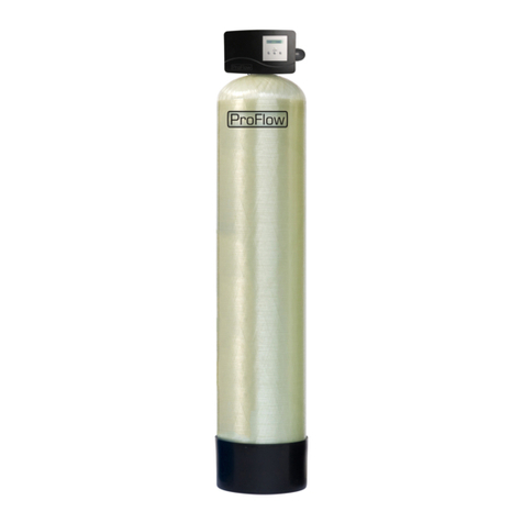
ProFlow PF-MMX Manual

© 2018 erie water treatment OM-PF-MMX-Rev2018.01
EN
Installation & Operating Instructions
MULTI PURPOSE WATER FILTER
FR
Instructions d’Installation & Emploi
FILTRE D’EAU MULTI-USAGE
DE
Installation- & Gebrauchsanleitung
MEHRZWECK WASSERFILTER
NL
Installatie & Gebruiksinstructies
MULTIFUNCTIONELE WATERFILTER
PL
Instrukcja Instalacji i Eksploatacji
MULTIFUNKCYJNY FILTR WODY
Models:
PF-MMX
PF-BTA

EN English .......................................................................................................................... Page 3
FR Français ........................................................................................................................ Page 17
DE Deutsch ........................................................................................................................ Seite 31
NL Nederlands................................................................................................................... Pagina 45
PL Polski ............................................................................................................................ Strona 59

TABLE OF CONTENT & INSTALLATION RECORD
Page 3 EN - English
Table of content & Installation record.....................................................................................Page 3
Warning & Safety instructions .................................................................................................Page 4
Operating conditions & Requirements ....................................................................................Page 5
Assembly ..................................................................................................................................Page 6
Installation ...............................................................................................................................Page 7
Commissioning.........................................................................................................................Page 8
Electronic control panel ...........................................................................................................Page 9
Maintenance ............................................................................................................................Page 13
Composition overview .............................................................................................................Page 14
Technical data - PF-MMX .........................................................................................................Page 15
Technical data - PF-BTA............................................................................................................Page 16
For future reference, fill in the following data
INSTALLATION RECORD
Serial number: _______________________________________________
Model: ________________________________________________________
Water hardness-inlet: _______________________________________
Iron / Manganese content-inlet: _________/ ____________
Ammonia (NH3) content-inlet: ______________________________
Water pressure-inlet: ________________________________________
Date of installation: __________________________________________
Company name: _____________________________________________
Installer name: _______________________________________________
Phone number: ______________________________________________

WARNING & SAFETY INSTRUCTIONS
EN - English Page 4
•Before you begin the installation of the appliance, we advise you read
and carefully follow the instructions contained in this manual. It contains
important information about safety, installation, use and maintenance of
the product. The actual system that you have received, may differ from
the pictures/illustrations/descriptions in these Instructions.
•Failure to follow the instructions could cause personal injury or damage
to the appliance or property. Only when installed, commissioned and
serviced correctly, the appliance will offer you many years of trouble-free
operation.
•The appliance is intended to 'filter' the water, meaning it will remove
specific undesired substances; it will not necessarily remove other
contaminants present in the water. The appliance will not purify polluted
water or make it safe to drink!
•Installation of the appliance should only be undertaken by a competent
person, aware of the local codes in force. All plumbing and electrical
connections must be done in accordance with local codes.
•Before setting up the appliance, make sure to check it for any externally
visible damage; do not install or use when damaged.
•Use a hand truck to transport the appliance. To prevent accident or
injury, do not hoist the appliance over your shoulder. Do not lay the
appliance on its side.
•Keep these Instructions in a safe place and ensure that new users are
familiar with the content.
•The appliance is designed and manufactured in accordance with current
safety requirements and regulations. Incorrect repairs can result in
unforeseen danger for the user, for which the manufacturer cannot be
held responsible. Therefore repairs should only be undertaken by a
competent technician, familiar and trained for this product.
•In respect of the environment, this appliance should be disposed of in
accordance with Waste Electrical and Electronic Equipment
requirements. Refer to national/local laws and codes for correct recycling
of this appliance.

OPERATING CONDITIONS & REQUIREMENTS
Page 5 EN - English
•APPLICATION LIMITATIONS:
pH: 5-10
maximum contaminant content:
Water hardness
75 °f / 42 °d
Iron (Fe2+)
15 mg/L
Manganese (Mn2+)
3 mg/L
Oxidizability (O2)
4 mg/L
Ammonia (NH3)
4 mg/L
•OPERATING PRESSURE MIN-MAX: 1,4-8,0 bar / 20-116 psi
this appliance is configured to perform optimally at an
operating pressure of 3 bar (45 psi) ±½ bar (7 psi); in case of a
lower or higher operating pressure the performance may be
affected negatively!
check water pressure regularly; it may fluctuate severely
depending on the time of day, the day of the week or even the
season of the year.
take into account that night time water pressure may be
considerably higher than day time water pressure.
install a pressure reducer ahead of the appliance if necessary.
install a pressure booster, if it is likely that water pressure may
drop below the minimum.
•OPERATING TEMPERATURE MIN-MAX: 2-48 °C / 35-120 °F
do not install the appliance in an environment where high
ambient temperatures (e.g. unvented boiler house) or freezing
temperatures can occur.
the appliance cannot be exposed to outdoor elements, such as
direct sunlight or atmospheric precipitation.
do not install the appliance too close to a water heater; keep at
least 3 m (10 ft) of piping between the outlet of the appliance
and the inlet of the water heater; water heaters can sometimes
transmit heat back down the cold pipe into the appliance;
always install a check valve at the outlet of the appliance.
•ELECTRICAL CONNECTION:
this appliance only works on 24 VDC; always use it in
combination with the supplied transformer.
in case of damage to the power supply cable of the transformer,
immediately disconnect the transformer from the power outlet
and replace the transformer.
make sure to plug the transformer into a power outlet, which is
installed in a dry location, with the proper rating and over-
current protection.

ASSEMBLY
EN - English Page 6
CONTENT CHECK
Actual parts that you have received, may differ from the
pictures/illustrations in these Instructions!
For ease of transportation and installation, the softening
resin is NOT loaded in the pressure tank, but delivered in
separate bags of 12 or 25 ltr; it must be loaded on-site, after
positioning of the pressure tank.
Check the content of the system, using the Composition
Overview at the end of these Instructions. Identify and lay-out
the different components to facilitate the assembly.
FILTER MEDIA LOADING
1. Move the pressure tank to the correct installation
location; position it on a flat and level surface. Make sure
to leave enough space for ease of service.
2. Position the riser assembly upright and centred in the
pressure tank; plug the top of the riser tube with a piece
of tape or clean rag, to prevent filter media from entering
the tube.
3. Add water to the pressure tank to a height of ±30 cm from
the bottom; this water will protect the bottom of the
pressure tank and the bottom distributor, during filling of
the pressure tank.
4. Place a funnel on the pressure tank opening and fill the
pressure tank with filter media; make sure the riser
assembly remains centered in the pressure tank.
5. Rinse the pressure tank opening to remove any grains of
filter media from the threaded section.
6. Unplug the top of the riser tube.
CONTROL VALVE
1. Make sure the O-ring in the riser insert and the tank O-
ring (around the threaded section of the control valve) are
in the correct position.
2. Screw the top distributor onto the control valve.
3. Lubricate the threaded section of the pressure tank, the
top of the riser tube and the tank O-ring of the control
valve; use a silicon-based lubricant.
4. Lower the control valve straight down onto the riser tube,
until the riser tube is correctly inserted in the riser insert;
then push it down firmly and screw it onto the pressure
tank.
BRINE TANK ASSEMBLY (PF-BTA) (optional)
Picture 1
1. Move the brine tank to the correct installation location;
position it on a flat and level surface. Make sure to leave
enough space for ease of service.
2. Insert the polytube into the brine line connection on the
control valve (); make sure to push the polytube in all
the way; tighten the nut.
3. Remove the lid from the brine tank.
4. Remove the lid from the brine well.
5. Make sure the correct elbow connection is installed on
the brine valve (⅜” for PF-MMX); replace if necessary.
6. Run the polytube from the control valve through the hole
in the sidewall of the brine tank, to the inside of the brine
tank.
7. Insert the polytube into the elbow connection on the
brine valve; make sure to push the polytube in all the way.
8. Install the lid on the brine well.
9. Add water to the brine tank to a height of ±10 cm from
the bottom.
10. Add salt to the brine tank.
11. Install the lid on the brine tank.

INSTALLATION
Page 7 EN - English
INLET & OUTLET
In case of high concentration of impurities in the inlet
water, we recommend the installation of a sediment filter,
ahead of the appliance.
We strongly recommend the use of flexible hoses to
connect the appliance to the water distribution system; use
hoses with a large diameter in order to limit the pressure
loss.
We strongly recommend the installation of a bypass
system (not included with this product!) to isolate the
appliance from the water distribution system in case of
repairs. It allows to turn off the water to the appliance, while
maintaining full-flow (untreated) water supply to the user.
with factory bypass (optional)
Picture 2
= mains water supply (untreated water)
❖= inlet of control valve (untreated water)
= outlet of control valve (treated water)
= application (treated water)
1. Screw the factory bypass onto the in/out ports on the
control valve (❖&); make sure to install the gasket
seals. Tighten the nuts firmly by hand.
2. Screw the connection kit with nuts onto the factory
bypass (&); make sure to install the gasket seals.
Tighten the nuts firmly by hand.
3. Connect the mains water supply to the adaptor on the
inlet port of the factory bypass ().
4. Connect the application to the adaptor on the outlet port
of the factory bypass ().
with 3-valve connection kit (not included)
Picture 3
= inlet of control valve (untreated water)
❖= outlet of control valve (treated water)
1. Install the 3-valve connection kit.
2. Screw the connection kit with nuts onto the in/out ports
on the control valve (&❖); make sure to install the
gasket seals. Tighten the nuts firmly by hand.
3. Connect the IN valve of the 3-valve connection kit to the
adaptor on the in port of the control valve ().
4. Connect the OUT valve of the 3-valve connection kit to the
adaptor on the out port of the control valve (❖).
5. Connect the mains water supply to the inlet of the 3-valve
connection kit.
6. Connect the application to the outlet of the 3-valve
connection kit.
DRAIN
We recommend the use of a stand pipe with P-trap.
To prevent backflow from the sewerage system into the
appliance, always ensure sufficient air gap between the end
of the drain hose or pipe and the sewerage system.
Always use separate drain hoses for the control valve
(discharge of rinse water) and the brine tank overflow.
Lay-out the drain hoses in such a way that pressure loss
is minimized; avoid kinks and unnecessary elevations.
Make sure that the sewerage system is suitable for the
rinse water flow rate of the appliance.
for PF-MMX
Picture 4
1. Connect the 19 mm hose to the drain connection of the
control valve (); secure it by means of the clamp.
2. Run the drain hose to the sewerage system and connect
it, ensuring sufficient air gap between the end of the hose
and the sewerage system. This drain line operates under
pressure, so it may be installed higher than the appliance.
PF-BTA: brine tank assembly (optional)
1. Connect the 19 mm hose to the overflow elbow on the
brine tank; secure it by means of the clamp.
2. Run the drain hose to the sewerage system and connect
it, ensuring sufficient air gap between the end of the hose
and the sewerage system. This drain line does NOT
operate under pressure, so it may NOT be installed higher
than the brine tank.

COMMISSIONING
EN - English Page 8
ELECTRICAL
1. Connect the appliances power cord to the transformers
output.
2. Plug the transformer into an electrical outlet.
PRESSURIZING
1. Put the bypass system in 'bypass' position.
2. Make sure the electronic controller of the appliance is in
service mode.
3. Open the mains water supply.
4. Open a cold treated water faucet nearby the appliance
and let the water run for a few minutes until all air is
purged and all foreign material that may have resulted
from the installation is washed out; close the tap.
5. Gently pressurize the appliance, by putting it into service:
•close the 'BYPASS' valve;
•open the 'OUT' valve;
•slowly open the 'IN' valve.
6. After 2-3 minutes, open a cold treated water faucet
nearby the appliance and let the water run for a few
minutes until all air is purged from the installation and the
resin bed is rinsed (it is normal for the rinse water to show
some discoloration!); close the tap.
7. Check the appliance and all hydraulic connections for
leaks.
ELECTRONIC CONTROL PANEL
1. Program the electronic controller.
INITIATE A REGENERATION
1. Manually initiate a regeneration, by pressing the scroll
button; the display will show:
2. Leave the appliance in this position; the count-down
timer will count down to 0 sec and start a regeneration;
to save time you may skip, or terminate prematurely, the
second cycle of the regeneration by pressing the scroll
button once, as soon as the display indicates that the
system is in the second regeneration position.
Regen in 10 sec

ELECTRONIC CONTROL PANEL
Page 9 EN - English
Picture 5
symbol
button
function
SCROLL
to advance to the next
parameter
UP
to increase the value of the
parameter
DOWN
to decrease the value of the
parameter
POWER-UP
After power-up the display will show the installed software
version for a period of 5 seconds.
POWER FAILURE
In the event of a power failure, the program will remain
stored in the NOVRAM® during an undefined period, while an
incorporated SuperCap will maintain the correct time of day
during a period of several hours; consequently, in case of
prolonged power failure, the time of day might not be
maintained; if this happens, the time of day will be reset to
8:00 when the power supply is re-established, while the
indication will flash, indicating that the time of day needs to
be set.
When the power failure occurs during the execution of an
automatic regeneration, the control valve will remain in its
last position; when the power supply is re-established, the
control valve will return to the service position, stay there for
60 sec. and restart a complete regeneration from the
beginning.
TIMER FAILURE
In the event of a timer failure, the display will show the
message:
The buzzer, if enabled (see Basic Settings), will beep
continuously. If powering off/on the appliance doesn’t solve
this problem, professional service is required.
MAINTENANCE REMINDER
Only available if the maintenance reminder function has
been activated and programmed by your supplier!
Once the maintenance interval is reached, the following will
happen:
1. the display will intermittently show the message:
2. the buzzer, if enabled (see Basic Settings), will beep 3
times every hour.
While the appliance will continue to operate normally, it is
recommended to have preventive maintenance performed
by a professional.
SERVICE MODE
In service mode the display shows:
•on 1st line: the time of day and the remaining capacity;
•on 2nd line: the total volume of water used since
commissioning.
REGENERATION MODE
In regeneration mode the display shows the total remaining
regeneration time and remaining cycle time:
The appliance can be reset to service mode at any time by
pressing the scroll button, as such manually advancing it
through the regeneration cycles.
MANUAL REGENERATION
It is possible to manually initiate an immediate regeneration
or a delayed regeneration (at the preprogrammed time of
regeneration).
1. Press the scroll button; the display will show:
•If the control panel is left in this position, the
countdown timer will countdown to 0 sec and start an
immediate regeneration.
•To cancel this mode, press the scroll button before
the countdown timer has reached 0 sec; the display
will show:
•If the control panel is left in this position, a delayed
regeneration will be started at the indicated
preprogrammed time of regeneration.
•To cancel this mode, press the scroll button
repeatedly; the control panel will return to the service
mode.
HOLIDAY MODE
It is possible to put the appliance in holiday mode; this will
prevent automatic regeneration from taking place, yet will
ensure the appliance is automatically regenerated at the end
of the holiday cycle.
Rgn:XXX CycY:ZZZ
8:01 1000L –
Maintenance Now
Service Required
8:01 1000L –
TotVol: 1234567L
Regen in 10 sec
Regen @ 2:00

ELECTRONIC CONTROL PANEL
EN - English Page 10
1. Press the scroll button repeatedly until the display
shows:
•Press the up or down button to activate the
holiday mode by setting the number of full days away
from home,or deactivate the holiday mode (OFF).
Once the control panel is back in service mode, the display
will show:
The holiday mode is automatically cancelled when a
regeneration is manually initiated!
PROGRAMMING INSTRUCTIONS -
BASIC SETTINGS
Before entering the programming mode, make sure that
the appliance is in service mode.
In case no button is pressed in a period of 5 min, the
control panel will automatically return to the service mode;
any changes made will NOT be saved!
1. Press the scroll button and hold it for 2 sec until the
display shows:
•Press the up or down button to set the
language.
2. Press the scroll button again; the display will show:
•Press the up or down button to set the time of
day.
3. Press the scroll button again; the display will show:
•Press the up or down button to set the unit of
measure for water hardness. Make sure it is identical
to the unit of measure of the water hardness test kit
or water analysis report that is used to determine the
hardness of the incoming untreated water!
4. Press the scroll button again; the display will show:
•Press the up or down button to set the hardness
of the incoming untreated water.
5. Press the scroll button again; the display will show:
•Press the up or down button to enable or
disable the buzzer.
6. Press the scroll button again; the display will show:
•Press the up or down button to save the settings
into the NOVRAM® and exit the programming mode.
Holiday: OFF
8:01 Holiday
Language:English
Set time: 8:01
Set hardn: XX °f
HardUnit: °f
Exit
Buzzer: ON

ELECTRONIC CONTROL PANEL
Page 11 EN - English
PROGRAMMING INSTRUCTIONS -
CONFIGURATION PARAMETERS
Before entering the programming mode, make sure that
the appliance is in the service mode.
All configuration parameters on this appliance have
been pre-programmed in the factory, to offer optimal
performance in a wide range of applications and situations.
Nevertheless it may be necessary or desirable to change any
of these parameters, to further optimize the appliances
performance or to adapt it to the specific requirements of
the installation.
In case no button is pressed in a period of 5 min, the
control panel will automatically return to the service mode;
any changes made will NOT be saved!
1. Press the scroll button and hold it for 6 sec until the
display shows:
2. Within 10 sec, press the up button; the display will
show:
•Press the up or down button to set the units of
measure (Metric or US).
3. Press the scroll button again on; the display will show:
•Press the up or down button to activate the
maintenance reminder function by setting the
maintenance interval, or deactivate the maintenance
reminder function.
4. Press the scroll button again; the display will show:
•Press the up or down button to set the
exchange capacity per litre of resin.
5. Press the scroll button again; the display will show:
•Press the up or down button to set the age
correction factor (%/year) to compensate for capacity
loss of the resin due to aging.
6. Press the scroll button again; the display will show:
•Press the up or down button to set the volume
of resin.
7. Press the scroll button again; the display will show:
•Press the up or down button to set the number
of days between regenerations.
8. Press the scroll button again; the display will show:
•Press the up or down button to set the length
of the regeneration cycle.
•Press the scroll button again to advance to the next
regeneration cycle.
Cycle 1
Backwash
Cycle 2
Brine draw/slow rinse
Cycle 3
Fast rinse/brine tank refill
9. Press the scroll button again; the display will show:
•Press the up or down button to set the
regeneration mode:
Dlyd/Immd: when the remaining capacity equals
the reserve capacity, a delayed regeneration at
the programmed time of regeneration is started;
however when the remaining capacity equals 0
before the programmed time of regeneration is
reached, an immediate regeneration is started.
Immediate: when the remaining capacity equals
0, an immediate regeneration is started.
Note: Delayed manual regeneration is not
available when this regeneration mode is
selected.
Delayed: when the remaining capacity equals the
reserve capacity, a delayed regeneration at the
programmed time of regeneration is started.
10. Press the scroll button again; the display will show
(only when the regeneration mode is set to ‘Delayed’or
‘Dlyd/Immd’):
•Press the up or down button to set the time of
regeneration.
Cycle 1: XX min
System Check
Regen @ 2:00
Resin:XXX liters
ExCap:3.8°f M3/L
Override: 4 days
Regen:Dlyd/Immd
MaintInt: 24mths
Age corr.: 2.0%
Units:Metric

ELECTRONIC CONTROL PANEL
EN - English Page 12
11. Press the scroll button again; the display will show
(only when the regeneration mode is set to ‘Dlyd’or
‘Dlyd/Immd’):
•Press the up or down button to set the reserve
capacity:
Variable: the reserve capacity is calculated
automatically, based on the registered daily water
usage.
Fxd: press the scroll button again and press the
up or down button to set the reserve
capacity to a fixed amount.
12. Press the scroll button again; the display will show:
•Press the up or down button to set the function
of auxilliary contact 2:
Regen: aux. contact is powered during entire
regeneration (does not include refill and brine
preparation cycles!).
Chlor.Cell: aux. contact is powered at start of
brine draw/slow rinse cycle. Press the scroll
button again and press the up or down
button to set the duration of activation of the
chlorination cell.
Maintenance: aux. contact is powered when
Maintenance Reminder is triggered.
Error: aux. contact is powered when timer failure
occurs.
13. Press the scroll button again; the display will show:
•Press the up or down button to save the
program into the NOVRAM® and exit the
programming level.
Exit
Rsrv:Variable
AUX2: Regen

MAINTENANCE
Page 13 EN - English
RECOMMENDATION
Notwithstanding the reliability of the appliance, we strongly
recommend to have it serviced and maintained on a regular
basis by a competent and duly trained technician. He will be
able to determine the appropriate maintenance interval for
the appliance, depending on your specific application and the
local operating conditions. The advantages of performing
regular maintenance are:
•regular check of the local operating conditions (water
quality, pressure, etc);
•regular control and adjustment of the settings of the
appliance, to guarantee it operates at maximum
efficiency;
•minimize the risk of unexpected break-down.
Contact your dealer or installer for more information, or visit
our website.
ROUTINE CHECKS
Regularly the user should perform a basic check to verify if the
appliance is functioning correctly, on the basis of the
following control points:
1. Check settings of electronic control panel.
2. Check water composition before/after appliance.
3. Check drain line from control valve; there shouldn’t be
any water flow (unless appliance is in regeneration).
4. Check drain line from brine tank overflow; there shouldn’t
be any water flow.
5. Check appliance and surrounding area; there shouldn’t be
any water leakages.
BYPASSING THE APPLIANCE
Occasionally it may be necessary to put the appliance
hydraulically in bypass, i.e. to isolate it from the water
distribution system; f.e.:
•in case of an urgent technical problem;
•when it is not necessary to supply treated water to the
application.
WITH FACTORY BYPASS (optional)
Picture 6.a
SERVICE POSITION
= inlet valve to appliance is OPEN
❖= outlet valve from appliance is OPEN
Picture 6.b
BYPASS POSITION
= inlet valve to appliance is CLOSED
❖= outlet valve from appliance is CLOSED
Picture 6.c
MAINTENANCE POSITION
= inlet valve to appliance is OPEN
❖= outlet valve from appliance is CLOSED
WATER CONDITIONER SALT
This appliance needs 'brine' for its periodic regenerations.
This brine solution is made from water, that is automatically
dosed in the brine tank by the control valve, and water
conditioner salt. The user should make sure that the brine
tank is always kept full of water conditioner salt. Therefore he
should periodically check the salt level inside the brine tank
and refill it if necessary. Simply lift the brine tank cover to
check the salt level inside the brine tank.
Ideally the level of water conditioner salt inside the brine tank
is kept between 1/3 and 2/3. A lower level of water
conditioner salt can cause insufficient brine saturation,
resulting in a loss of softening capacity. A higher level of water
conditioner salt can cause salt bridging (hard crust or salt
bridges in the brine tank). When you suspect salt bridging:
•carefully pound on the outside of the brine tank to break
loose the salt bridges;
•using a broom (or like blunt tool) carefully push the salt to
break it apart;
•pour warm water over the top of the salt to dissolve it.
FILTER MEDIA CLEANER
Other contaminants present in the feed water can cause the
filter media (especially the ion exchange resin) to foul up,
resulting in a loss of filtration capacity. An approved filter
media cleaner can be used periodically to thoroughly clean
the filter media.
SANITIZING THE APPLIANCE
This appliance is manufactured from premium quality
material and assembled in safe conditions to assure it is clean
and sanitary. If installed and serviced correctly, this appliance
will not infect or contaminate your water supply. However, as
in any 'device' plumbed-in in your water distribution system,
a proliferation of bacteria is possible, especially in case of
'stagnant water'. Therefore this appliance is equipped with a
'days override' feature, that will automatically rinse the resin
bed periodically, even in case of low or absence of water
usage.
If the power supply to the appliance is disconnected for a
longer period of time, we recommend, when the power
supply is re-established, to manually initiate a complete
regeneration.

TECHNICAL DATA - PF-MMX
Page 14
Model
Media volume
PN
Control valve, incl. transformer,
1” BSP male connections
Pressure tank,
incl. distributor assy
Filter media
(12 kg bag)
(25 kg bag)
Ltr
model
#
model
#
#
#
PF-MMX
25
35690
2400VS/J4JB/PRL1
1
10x35
1
0
1
37
35691
2400VS/J1JB/PRL1
1
10x47
1
1
1
50
35692
2400VS/J1LD/PRL1
1
12x48
1
0
2
75
35693
2400VS/J1ND/PRL1
1
14x65
1
0
3

COMPOSITION OVERVIEW
Page 15 EN - English
Technical specifications:
(1) Supplied with 24 VDC transformer
Performances @ 3 bar operating pressure(2):
(2) Indicative numbers, performances depending on operating conditions and water quality
Model
PF-MMX
Filter media (ltr)
25
37
50
75
Nominal exchange capacity (m³x°f)
95
141
190
285
Nominal exchange capacity (m³x°d)
53
79
106
160
Service flow rate @∆p 1 bar (m³/hr)
3,3
3,4
3,5
3,5
Salt usage per regeneration (kg)
2,5
3,7
5,0
7,5
Rinse water usage per regeneration (ltr)
205
248
354
531
Max. flow to drain (ltr/min)
9,8
9,8
15,1
22,7
Dimensions:
Model
PF-MMX
Filter media (ltr)
25
37
50
75
Width (mm) (W)
264
264
311
365
Depth (mm) (D)
282
282
311
365
Depth, incl. factory bypass (mm) (D)
371
371
376
403
Height (mm) (H)
1.059
1.366
1.394
1.836
Model
PF-MMX
Filter media (ltr)
25
37
50
75
Operating pressure min/max (bar)
1,4/8,3
Operating temperature min/max (°C)
2/48
Electrical connection (V/Hz)
230/50(1)
Max. power consumption (VA)
8
Hydraulic connection inlet/outlet
1” BSP Male
Hydraulic connection drain
19 mm hose barb
Hydraulic connection brine tank
⅜” compression fitting
Pressure tank
10x35
10x47
12x48
14x65

TECHNICAL DATA - PF-BTA
Page 16
Technical specifications:
Dimensions:
Model
PF-BTA
Volume (ltr)
125
275
Diameter (mm) (D)
540
685
Height (mm) (H)
850
975
Height overflow (mm) (H1)
660
825
Max. salt storage capacity (kg)
100
200
Model
PF-BTA
Volume (ltr)
125
275
Hydraulic connection brine valve
⅜” Quick-Fit
Hydraulic connection overflow
19 mm hose barb

TABLE DES MATIÈRES & DONNÉES D’INSTALLATION
Page 17 FR - Français
Table des matières & Données d’installation ..........................................................................Page 17
Mesures de précaution & Consignes de sécurité ....................................................................Page 18
Conditions de fonctionnement & Exigences............................................................................Page 19
Assemblage ..............................................................................................................................Page 20
Installation ...............................................................................................................................Page 21
Mise en marche........................................................................................................................Page 22
Panneau de commande électronique......................................................................................Page 23
Entretien...................................................................................................................................Page 27
Liste de composition ................................................................................................................Page 28
Données techniques - PF-MMX ...............................................................................................Page 29
Données techniques - PF-BTA..................................................................................................Page 30
Pour future référence, notez les données suivantes
DONNÉES D’INSTALLATION
Numéro de série: ____________________________________________
Modèle: _______________________________________________________
Dureté d’eau-entrée: ________________________________________
Teneur en Fer / Manganèse-entrée: _______/___________
Teneur en Ammonium (NH3)-entrée:_______________________
Pression d’eau-entrée: ______________________________________
Date d’installation: __________________________________________
Nom société: _________________________________________________
Nom installeur: _______________________________________________
Numéro de tél.: ______________________________________________

MESURES DE PRÉCAUTION & CONSIGNES DE SÉCURITÉ
FR - Français Page 18
•Avant d’entamer l’installation de l’appareil, nous vous recommandons de
lire et suivre attentivement les instructions dans ce manuel. Il contient
des informations importantes concernant la sécurité, l’installation,
l’usage et l’entretien du produit. L’appareil que vous avez reçu peut
différer des photos/illustrations/descriptions dans ces Instructions.
•Ne pas suivre les instructions du manuel peut causer des blessures
personnelles et/ou endommager le produit. Seulement s’il est installé,
mis en route et entretenu de manière correcte, l’appareil vous offrira de
pleines années de service exempt de pannes.
•L’appareil est destiné à 'filtrer' l’eau, c’est à dire il enlèvera certaines
substances indésirables; il n’enlèvera pas nécessairement d’autres
contaminants présents dans l’eau. L’appareil ne rendra pas de l’eau
polluée pure ni potable!
•L’installation de l’appareil doit être effectuée par une personne
compétente, au courant des codes locaux en vigueur. Tous les
raccordements hydrauliques et électriques doivent être réalisés en
concordance aux codes locaux.
•Avant d’installer l’appareil, veuillez inspecter l’appareil pour contrôler s’il
n’y a pas de dommages visibles; n’installez pas l’appareil s’il est
endommagé.
•Utiliser une charrette pour transporter l’appareil. Afin d’éviter tout
accident ou blessure, ne hisser pas l’appareil sur votre épaule. Ne mettez
pas l’appareil sur son côté.
•Conservez ces Instructions dans un endroit sûr et veillez à informer de
nouveaux utilisateurs de son contenu.
•L’appareil est dessiné et fabriqué en concordance aux consignes de
sécurité et régulations actuelles. Des réparations incorrectes peuvent
mettre en péril le matériel de l’utilisateur, pour lequel le fabricant ne peut
pas être rendu responsable. Pour cette raison toute réparation ne peut
être effectuée que par un technicien compétent et formé pour ce
produit.
•En respect de l’environnement, cet appareil devrait être recyclé en
concordance à la loi Déchets d’Equipements Électriques et Électroniques
(DEEE). Vérifier les lois et codes nationaux/locaux pour le recyclage
correct de cet appareil.

CONDITIONS DE FONCTIONNEMENT & EXIGENCES
Page 19 FR - Français
•LIMITATIONS D’APPLICATION:
pH: 5-10
teneur maximal de contaminant:
Dureté d’eau
75 °f / 42 °d
Fer (Fe2+)
15 mg/L
Manganèse (Mn2+)
3 mg/L
Oxydabilité (O2)
4 mg/L
Ammoniac (NH3)
4 mg/L
•PRESSION DE SERVICE MIN-MAX: 1,4-8,0 bar / 20-116 psi
cet appareil est configuré pour fonctionner de manière optimale à
une pression de service de 3 bar (45 psi) ±½ bar (7 psi); une pression
de service inférieure ou supérieure peut affecter les performances
de manière négative!
contrôlez régulièrement la pression d’eau ; elle peut fluctuer
considérablement selon l’heure du jour, le jour de la semaine ou
même le saison de l’année.
prenez en considération que la pression d’eau pendant la nuit peut
être considérablement plus élevée que la pression d’eau pendant la
journée.
installez un réducteur de pression en amont de l’appareil si
nécessaire.
installez un surpresseur, s’il est probable que la pression d’eau peut
descendre en dessous du minimum.
•TEMPÉRATURE DE SERVICE MIN-MAX: 2-48 °C / 35-120 °F
n’installez pas l’appareil dans un endroit où des températures élevées
(Ex: chaufferie non-ventilée) ou de gel peuvent se présenter.
l’appareil ne peut pas être exposé aux éléments extérieurs, comme la
lumière directe du soleil ou précipitation atmosphérique.
n’installez pas l’appareil trop proche d’une chaudière; conservez au
moins 3 m de conduite entre la sortie de l’appareil et la chaudière;
une chaudière peut transmettre, à travers la conduite d’alimentation
d’eau froide, de la chaleur dans la vanne de commande; installez
toujours un clapet anti-retour à la sortie de l’appareil.
•ALIMENTATION ÉLECTRIQUE:
l’appareil fonctionne uniquement en 24 VDC; utilisez l’appareil
toujours en combinaison avec le transformateur fourni.
en cas de dommages au câble d’alimentation du transformateur,
débranchez immédiatement le transformateur de la prise de courant
et remplacez le transformateur.
branchez le transformateur dans une prise de courant, installée dans
un endroit sec, de la tension correcte et munie d’une protection
adéquate contre toute surtension.
ASSEMBLAGE
FR - Français Page 20
VÉRIFICATION DU CONTENU
Les composants que vous avez reçu, peuvent différer des
photos/illustrations dans ces Instructions!
Pour faciliter le transport et l’installation, la résine n’est
PAS mise dans la bouteille à pression, mais fournie en sacs
séparés de 12 ou 25 ltr; elle doit être mise sur site, après mise
en position de la bouteille à pression.
Vérifiez le contenue du système; reportez-vous à la Liste de
Composants au dos de ces Instructions. Identifiez et étalez
les différents composants pour faciliter l’assemblage.
REMPLISSAGE DE LA MASSE FILTRANTE
1. Placez la bouteille à pression sur l’emplacement
d’installation correcte; positionnez-le sur une surface
égale et horizontale. Laissez suffisamment d’espace pour
effectuer l’entretien.
2. Placez le tube de distribution verticale et centré dans la
bouteille à pression; bouchez le bout du tube plongeur
avec un morceau de ruban adhésif ou tissu, pour éviter
que la masse filtrante entre dans le tube.
3. Mettez de l’eau dans la bouteille à pression jusqu’à une
hauteur de ±30 cm du fond; cet eau protègera le fond de
la bouteille à pression et le distributeur inférieur, durant
le remplissage de la bouteille à pression.
4. Mettez un entonnoir sur l’ouverture de la bouteille à
pression et versez la masse filtrante dans la bouteille à
pression; vérifiez que le tube de distribution reste centré
dans la bouteille à pression.
5. Rincez l’ouverture de la bouteille à pression afin d’enlever
d’éventuelles graines de masse filtrante dans la section
filetée.
6. Débouchez le bout du tube plongeur.
VANNE DE COMMANDE
1. Vérifiez que le joint dans l’adaptateur de tube plongeur et
le joint de la bouteille à pression (autour de la section
filetée de la vanne de commande) se trouvent dans la
position correcte.
2. Vissez la crépine supérieure sur la vanne de commande.
3. Lubrifiez la section filetée de la bouteille à pression, le
bout du tube plongeur et le joint de la bouteille à pression
sur la vanne de commande; utilisez un lubrifiant à base de
silicone.
4. Faites descendre la vanne de commande droit sur le tube
plongeur, jusqu’à ce que le tube plongeur soit
correctement inséré dans l’adaptateur de tube plongeur;
ensuite poussez la vers le bas et vissez la sur la bouteille à
pression.
ENSEMBLE BAC À SEL (PF-BTA) (optionnel)
Image 1
1. Placez le bac à sel sur la position d’installation correcte;
positionnez-le sur une surface égale et horizontale.
Laissez suffisamment d’espace pour aise d’entretien.
2. Insérez le polytube dans le raccord à saumure sur la vanne
de commande (); serrez l’écrou.
3. Enlevez le couvercle du bac à sel.
4. Enlevez le couvercle de la cheminée à saumure.
5. Assurez-vous que le raccord coudé correct est installé sur
la vanne à saumure (⅜” pour PF-MMX).
6. Acheminez le tube flexible de la vanne de commande par
le trou dans le côté du bac à sel, à l’intérieur du bac à sel.
7. Insérez le tube flexible dans le raccord coudé sur la vanne
à saumure ; veillez à l’enfoncer complètement.
8. Mettez de l’eau dans le bac à sel jusqu’à une hauteur de
±10 cm du fond du bac à sel.
9. Mettez du sel dans le bac à sel.
10. Installez le couvercle sur la cheminée à saumure.
11. Installez le couvercle sur le bac à sel.
Other manuals for PF-MMX
1
This manual suits for next models
1
Table of contents
Languages:
Other ProFlow Water Filtration System manuals
Popular Water Filtration System manuals by other brands

Matheson
Matheson 6124 instructions

3M
3M AP11T Installation and operating instructions

Teka
Teka filtoo operating instructions

Greenway Home Products
Greenway Home Products Dual Stage Water Filtration System VGS2-PC Use and care guide

Philips
Philips ADD6910 user manual

Grunbeck
Grunbeck desaliQ Operation manual