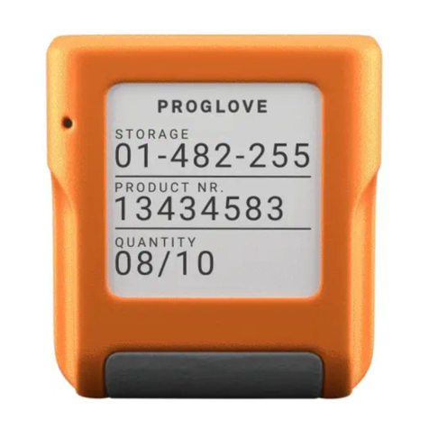
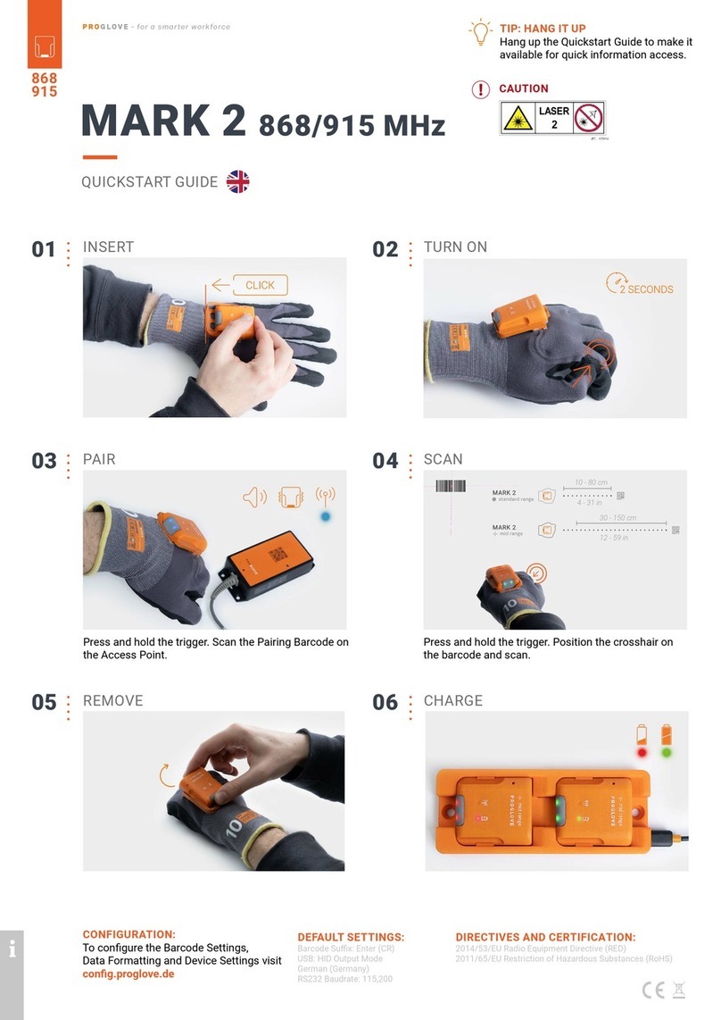
ProGlove LEO User manual

Technical document
PROGLOVE
USER MANUAL

PROGLOVE USER MANUAL
TABLE OF CONTENTS
SAFETY INSTRUCTIONS
Hardware & Wearables ................................................. 5
SCOPE OF DELIVERY
Hardware & Wearables ................................................. 7
TECHNICAL PROPERTIES
Scanner .......................................................................... 8
Connectivity Device ........................................................ 10
Charging Station ............................................................ 11
Wearables ...................................................................... 14
SETUP OF PROGLOVE SYSTEM
1st step: Charge Scanner ................................................ 17
2nd step: Connect via Connectivity Device .................... 17
3rd step: Switch on Scanner .......................................... 18
4th step: Connect Scanner ............................................. 19
5th step: Scan ................................................................. 24
6th step: Disconnect ProGlove System ......................... 25
7th step: Release Scanner from Wearables .................. 29
CONFIGURING DEVICES AND
FIRMWARE UPDATES
1st step: Open configurations ....................................... 30
2nd step: Create a new configuration ............................ 30
3rd step: Connectivity configuration ............................. 30
4th step: Device settings ................................................. 31
5th step: Symbology settings ........................................ 31
6th step: Workflow rules ................................................ 31

7th step: Configure devices and Firmware Update ...... 32
SIGNAL TABLE
General Scanning .......................................................... 34
Connection via BLE ........................................................ 35
Gateway .......................................................................... 36
STORAGE AND CLEANING
Storage ........................................................................... 38
Cleaning ........................................................................ 38
SOLUTION TO THE PROBLEM
Scanner ........................................................................... 39
BLE - Data transfer ......................................................... 41
Gateway - Data transfer ................................................. 42
Charging Station ............................................................ 43
DISPOSAL .............................................................. 44
DIRECTIVES & CERTIFICATION ............. 44
SUPPORT
Technical support contact ............................................ 47
Sales contact ................................................................. 47

ABOUT THESE OPERATING
INSTRUCTIONS
CAUTION
Slight bodily injury or danger of physical damage to
ProGlove system is possible.
In addition, other symbols are used that mean the
following:
NOTE
Additional notices provide more information about the
respective chapter.
TIP
Additional tips facilitate the implementation of a
certain procedure.
RESULT
The result will show the outcome of the prior action.
ADDRESS:
Workaround GmbH ProGlove Inc.
Building 64.08a 520 W. Erie St.
Rupert-Mayer-Str. 44 Suite 400
81379 Munich Chicago, IL. 60654 / USA
FUNCTION OF THIS DOCUMENT
This user manual contains a system overview, technical data
about the Hardware and Wearables, detailed step-by-step
instructions for using ProGlove system and information about
configuration settings and troubleshooting.
It is intended for process planners, integrators and maintenance
technicians who are using ProGlove system for the first time. It
is designed so that ProGlove system can be used safely without
prior knowledge.
Read carefully before use and keep for future reference.
EXPLANATION OF
SYMBOLS
Warning notices are used throughout the instructions in the
user manual. Always read and pay attention to a warning
notice. A warning notice is introduced with the word CAUTION,
as shown below.
DOCUMENT TITLE: ProGlove User Manual
DATE OF PUBLICATION: 04/2022
VERSION: 1.0

SAFETY INSTRUCTIONS
HARDWARE WEARABLES
CAUTION
This may otherwise lead to damage or faults
due to overvoltage, line noise, electrostatic discharge
or other irregularities.
CAUTION
Otherwise the safe
functioning of ProGlove system cannot be ensured.
CAUTION
This may
otherwise lead to ProGlove system not functioning
properly.
CAUTION
This may
otherwise lead to ProGlove not functioning properly.
CAUTION
This may otherwise
lead to ProGlove system not functioning properly.
CAUTION
Otherwise the Wearables may
get stuck on objects.
CAUTION
Otherwise this may
cause pain or pressure points on your hand.


SCOPE OF DELIVERY
CAUTION
Do not use any damaged Hardware or Wearables!
Check whether Hardware and Wearables are properly packaged and undamaged.
SCANNER
LEO
WEARABLES
Index Trigger Hand Strap Reel
CHARGING STATIONS
Charging Station S / 10-Slot Charging Station with power cable (USB-C) and power supply

SCANNER
OVERVIEW
LEO
Connection
symbol
Battery
symbol
LED’s
After scanning a barcode, the scanner returns feedback signals: haptically by vibrations, acoustically by audio signals
and optically by LEDs.
Standard range:
4 - 28 in (10 - 70 cm)
Serial
number

TECHNICAL DATA - LEO
NOTE
Further technical specifications are available on
docs.proglove.de
BARCODE TYPES - 1D:
Auto decodes all standard 1D codes including GS1
DataBar linear codes et al.
BARCODE TYPES - 2D:
PDF417, MicroPDF417, Data matrix, QR Code, Micro
QR Code, Aztec, RSS, Composite, TLC-39, MaxiCode
et al.
BARCODE TYPES - POSTAL:
US PostNet, US Planet, UK Postal, Australia Postal,
Japan Postal, Dutch Postal (KIX) et al.
LED CLASSIFICATION:
Standard Range: Excluded risk group LED product
according to IEC/EN 62471
MECHANICAL PROPERTIES:
Dimensions: 1.47 x 1.77 x 0.67 in (50 x 45 x 17 mm)
Weight: 1.23 oz (35g)
ELECTRICAL PROPERTIES:
Battery type: Lithium polymer (rechargeable)
Charge duration: 1 hours
Number of scans: up to 4000 scans (depending on application
and environmental conditions)

CONNECTIVITY DEVICE
OVERVIEW GATEWAY
Pairing
Barcode
•LED 1 (USB LED)
•LED 2 (Scanner LED)
•LED 3 (Cloud LED) Label with serial number
Micro USB socket
The Gateway receives the scanned barcode data from the scanner via BLE. This barcode data is transmitted to the end
device via USB cable. In the USB HID mode, the Gateway simulates a computer keyboard. A serial connection is emulated
in the USB CDC mode. In order to use the USB CDC mode, the device must be set to “USB CDC” in the ProGlove Insight
Configuration Tool (https://insight.proglove.com/)
under “Connectivity Configuration - Integration path”. Also multipairing
is possible. The Gateway can be connected with up to 5 scanners simultaneously.

TECHNICAL DATA GATEWAY
NOTE
docs.proglove.de.
MECHANICAL PROPERTIES:
Dimensions: 3.74 x 2.06 x 0.94 in (95 x 52,3 x 23,8 mm)
Weight: 1.50 oz (42,5 g)
ELECTRICAL PROPERTIES:
Power supply of Access Point via USB cable: 5 VDC (0.5A) (via host computer)
UTILITIES & ACCESSORIES:
ProGlove Configuration Tool: https://insight.proglove.com/
Use for barcode, interface, device configuration et al.
UTILITIES & ACCESSORIES:
USB: USB HID (keyboard input on host)
USB CDC (virtual com port)
ProGlove Deep Integration Protocol via USB

CHARGING STATION S
OVERVIEW TECHNICAL DATA
USB-C
Charging tray
Attachment
opening for M5
screws Pins
Label with serial number
Attachment opening for cable ties
NOTE
Further technical specifications are available on
docs.proglove.de.
The Charging Station S consists of two charging trays
that charge two scanners at the same time. The charging
status is indicated by the LEDs of the scanner. The LEDs
pulse red while in charging mode. When the battery is
fully charged, the LEDs pulse green constantly. The
Charging Station S can be attached to work stations,
for example, through the attachment openings (with M5
screws or cable ties).
MECHANICAL PROPERTIES:
Dimensions: 5.5 x 2.2 x 0.7 in (140 x 56 x 19mm)
Weight: 4.4 oz (125g)
ELECTRICAL PROPERTIES:
Power supply: 5 VDC (1.2 A) via power supply
EU: SYS1561-1105
NA: SAW-06D-050-1200GB

10-SLOT CHARGING STATION
OVERVIEW TECHNICAL DATA
MOUNTING
MECHANICAL PROPERTIES:
Dimensions: 3.74 x 2.06 x 0.94 in
(298 x 203 x 25 mm)
Weight: 26.4 oz (750g)
ELECTRICAL PROPERTIES:
Power supply: 24 VDC (1.67A) via power supply
INT: GE40I 24-P1J
Use the provided power supply only.
Using any other type of AC power
supply is prohibited.
The 10-Slot Charging Station provides multiple options
to mount to flat surfaces, workstations and racks. The
charging status is indicated by the LEDs of the scanner. The
LEDs pulse red while in charging mode. When the battery is
fully charged, the LEDs pulse green constantly.
Do not mount the 10-Slot Charging Station higher than 2m!
On the front and back side are different holes and recesses
to enable secure mounting of the 10-Slot Charging Station
(with screws and/or zip-ties).
Two wall mount slots on the back side can be used to fix
the device with screw heads 135mm apart from each other.
The rail slot on the back enables mounting to a standard
DIN rail, facilitating the installation in an IT rack or similar
constructions. Additionally, the 10-Slot Charging Station
can be installed on a monitor arm or stand with holes 75mm
appart horizontally and vertically.
CAUTION

WEARABLES
HAND STRAP PROPERTIES
Fastening rail
for scanner
Trigger
NOTE
Further technical specifications are available on
docs.proglove.de.
Variable velcro connection
The ProGlove Hand Strap offers an elastic, adjustable Velcro
closure that ensures an optimal fit for any user's hand size
and shape. It can be worn with or without other gloves
underneath. The trigger is located on the side of the index
finger and is activated with the thumb. The Hand Strap is a
consumable that must be replaced regularly after use.
GENERAL:
Packaging unit: 3 or 10 pieces per package
Available sizes: one size
Available variants: right / left
SAFETY & CERTIFICATION:
Standards: EN388 (2131)
EN420
RoHS / REACH
CE mark

WEARABLES
INDEX TRIGGER PROPERTIES
Variable velcro connection
Fastening rail
for scanner
Trigger
Label with size indication
NOTE
Further technical specifications are available on
docs.proglove.de.
The ProGlove Index Trigger offers hand size optimized
variants and can be wrapped around the hand in one
movement. The thumb hole fixes the wrap in the correct
position and the flexible Velcro mechanism allows it to be
securely fastened to the user's hand. It can be worn with or
without other gloves underneath. The trigger is located on
the side of the index finger and is activated with the thumb.
The Index Trigger is a consumable that must be replaced
regularly after use.
GENERAL:
Packaging unit: 3 or 10 pieces per package
Available sizes: S, M, L
Available variants: right / left
SAFETY & CERTIFICATION:
Standards: EN388 (2131)
EN420
RoHS / REACH
CE mark

WEARABLES
REEL PROPERTIES
NOTE
Further technical specifications are available on
docs.proglove.de.
Module
clip
Trigger
Fastening clip (rotatable) Platform
Pins
The ProGlove Reel can be attached with the black, rotating
fastening clip to the desired spot. This can be, for example,
on the user's clothing or on a belt. Alternatively, the Reel
can also be worn on a lanyard around the neck. The trigger
is located on the bottom of the Reel and is activated by
pressing it. The cord between the mounting clip and the
scanner holder is 27 in (70 cm) long and retractable.
When retracted, the scanner holder is additionally fixed by
magnets to prevent it from dangling.
GENERAL:
Packaging unit: 2 reels per package
SAFETY & CERTIFICATION:
Certification: RoHS / REACH
CE mark

APPLICATION OF PROGLOVE SYSTEM
1ST STEP: CHARGE SCANNER 2ND STEP: CONNECT THE CONNECTIVITY DEVICE
CAUTION
Only use scanner in a dry Charging Station and
only touch with dry hands!
This may otherwise lead to the Charging Station
not functioning properly.
The pins face down.
Insert scanner in the
Charging Station.
RESULT
Scanner pulses red and charges in the Charging
Station.
NOTE
The LEDs pulse red while in charging mode. When
the battery is fully charged, the LEDs pulse green.
CAUTION
Only touch the connectivity device with dry hands! This may otherwise
lead to the connectivity device not functioning properly.
NOTE
The following steps are only needed when connecting via Gateway.
CONNECTION WITH USB CABLE IN USB HID MODE:
1. Connect the USB cable with the end
device. Follow the previous step 1 and step
2 for “Connetion with USB Cable in USB HID
Mode”. Continue with the following steps:
3. In the configuration tool
(https://insight.proglove.com/)
under “Connectivity Configuration >
Integration Path” select USB CDC.
More detailed information about this can be
found in chapter “Configure devices and firmware update.”

RESULT
The boot up of the Gateway takes around 2min until
the LED 1 lights up green. The connectivity device is
connected to the end device.
2. Plug the other end of the
USB cable into the Micro USB
socket of the Gateway. A
clear clicking sound confirms
the correct fastening.
4. Connect with the COM port on the end device.
RESULT
The boot up of the Gateway takes around 2min until
the LED 1 lights up green. The connectivity device is
connected to the end device.
3RD STEP: SWITCH ON THE SCANNER
1. Position scanner on the
fastening rail of the wearable.
The pins face down.
2. Push scanner down. A clear
clicking sound confirms the
correct fastening.
3. Press the textile trigger on
the glove for about 2 seconds
RESULT
Scanner lights up with all LEDs. You can hear a beeping
sound and feel a short vibration.
Scanner is switched on.
NOTE
Scanner switches off automatically after 15 minutes
without being used.

4TH STEP: CONNECT THE SCANNER
4TH STEP: CONNECT SCANNER (BLE)
CONNECT VIA PROGLOVE INSIGHT MOBILE:
For using a ProGlove scanner with ProGlove Insight Mobile
via software keyboard, Intent or SDK find more information
under docs.proglove.de> PG Insight Mobile.
CONNECT VIA CONNECTIVITY DEVICE
1. Press the trigger on the
wearable in order to activate the
scanner.
2. Aim scanner on the
connectivity device and scan
the pairing barcode on the
Gateway.
RESULT
Scanner lights up twice. You can hear a beeping sound
and feel a short vibration. Scanner is connected to the
connectivity device.
CONNECT VIA BLE HID TO AN END DEVICE
The scanner can be used to establish a connection via
Bluetooth Low Energy Human Interface Device (BLE HID) to
an end device. Possible operating systems are: Apple iOS, Google
Android, Microsoft Windows.
The individual steps for connecting to the respective operating
systems for the first time can be found in the following.
PREREQUISITES:
The end device supports at least Bluetooth 4.0 standard
No interference or physical obstacles (e.g. metal shelves)
interfere with the connection between the scanner and the
end device
The range between the scanner and the end device is
< 33 ft (10m)
TIP 1
Visually label the connected devices (scanner with the end
device), e.g.using numbering or a color code. This will
allow the user to find the right devices faster.
TIP 2
Adhere the pairing barcode to the end device. In this way,
the user can find it quickly and easily.

Under “Settings - Bluetooth,”
activate the Bluetooth option.
Select “LEO - 00000”.
01 02
LEO - 00000
On a battery-operated end device, the power-saving mode
can lock the end device and scanner simultaneously.
Permanently disable the power-saving mode of the end
device.
The last 5 digits of the serial number attached to the back
side identify the scanner among the available Bluetooth
devices.
Read the serial number of the scanner.
RESULT
Example serial number: LEO - 00000.
To make the scanner visible for the end device, the
scanner must be put into pairing mode:
1. Press the trigger on the
wearable in order to activate
the scanner.
2. Aim the scanner at the
pairing barcode and scan.
RESULT
Scanner pulses blue and beeping sounds can be heard.
Scanner is searching for an end device in pairing mode.
CONNECT WITH APPLE iOS 11 OR HIGHER:
Table of contents
Other ProGlove Barcode Reader manuals
Popular Barcode Reader manuals by other brands
Cognex
Cognex DataMan 8700 Quick reference guide
Datalogic
Datalogic Gryphon I GBT/GM4200 Series Quick reference guide
PSC
PSC Magellan 2200VS omega reference guide
APLIC
APLIC 303702/20190410GZ035 user manual
Socket
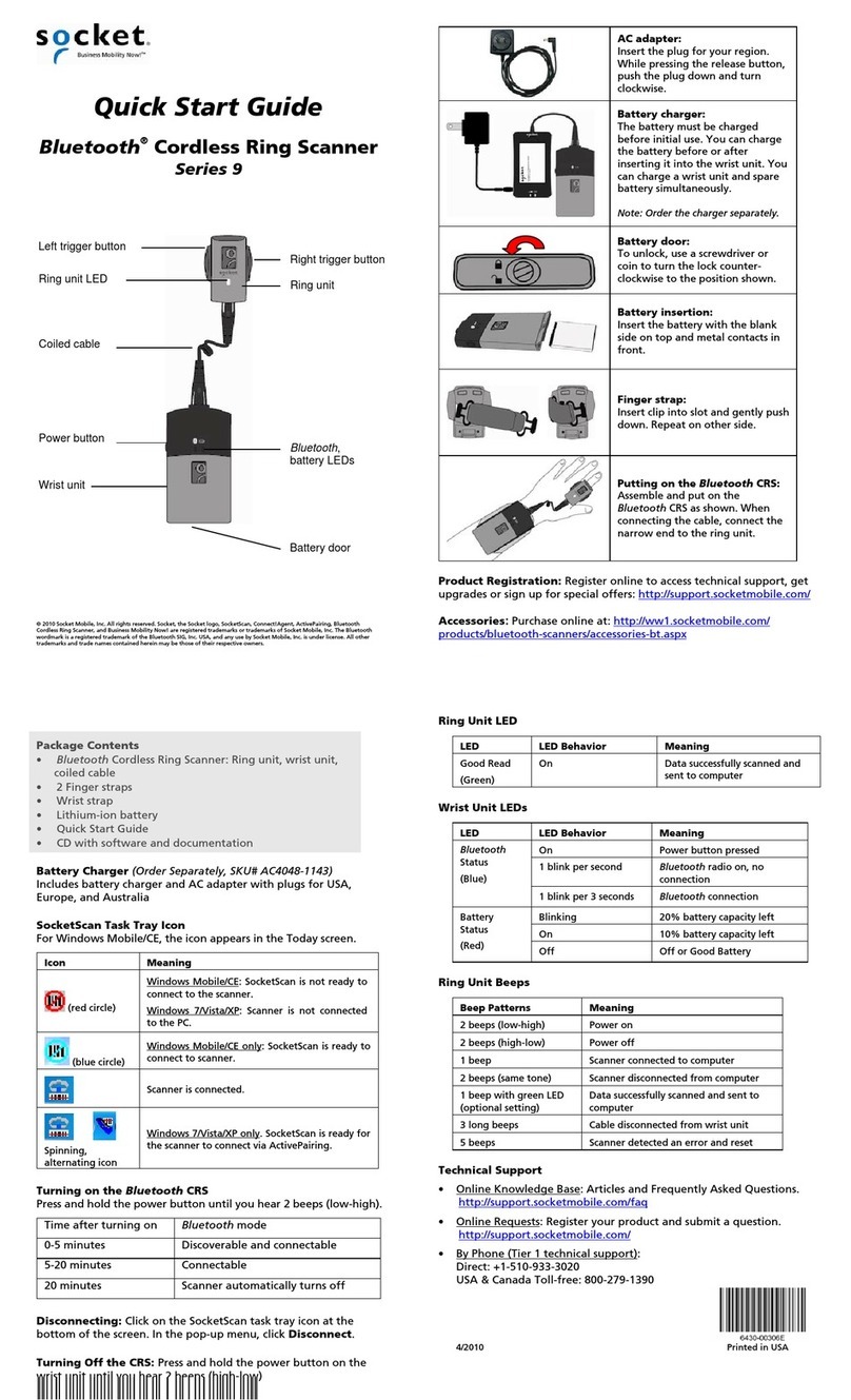
Socket Cordless Ring Scanner Series 9 quick start guide

Follett
Follett 6300 quick start guide
