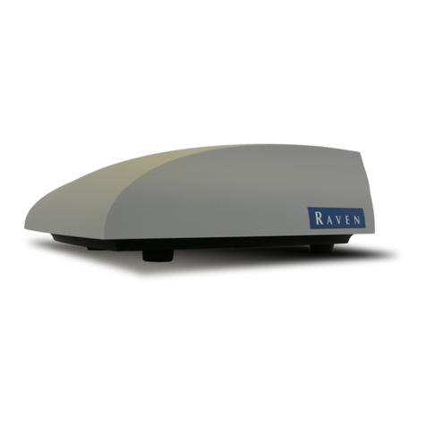
Raven CR7 User manual

User manual
CR7/CR12
QUICK START GUIDE
116-8000-017 REV. B2

| CR7/CR12 | QUICK START GUIDE
PAGE 2/35 | User manual |116-8000-017 |Rev. B2

DISCLAIMER | CR7/CR12 | QUICK START GUIDE
PAGE 3/35 | User manual |116-8000-017 |Rev. B2
DISCLAIMER
•The safety instructions contained in the manuals of the tractor or implements must be complied with at all
times.
•Always switch off the tractor before installing or repairing hydraulic and electrical components of the
SBGuidance system.
•It is strictly prohibited to use the CR7/CR12 system on public roads.
•It is strictly prohibited to leave a driving vehicle unattended when the CR7/CR12 system is switched on. The
driver is always responsible for the direction and course of the vehicle.
•To prevent injury or fire, replace defective fuses only with fuses of the same type and amperage.
•The SBGuidance the operating system is not able to detect and avoid obstacles. If there is an obstacle in your
path, you will always need to take action for it to be avoided.
•Only allow authorized/qualified persons to operate the system. Authorized/qualified persons are defined as:
persons who have read and understood the manual, have been given instructions by a product specialist, and
who are both physically and mentally fit and able to operate the system.
•The system contains moving parts! Make sure the immediate environment is clear of people before operating
the system.
•In case of system failure or breakdown switch of the tractor and disconnect the electrical power source to
avoid further damage. Contact your dealer for further instructions on how to repair your system.
•Always wear personal protective equipment when operating/adjusting/repairing the system outside of the
tractor cab.
•In order to prevent power surges from occurring, always start the machine first, before initiating the
SBGuidance control system.
•Only touch the touch-screen with your finger or by using a special touch-screen stylus/pen. Operating the
touch-screen with sharp objects may cause permanent damage to the screen.
•Always consult your supplier as to which products are best suited first before cleaning the touch-screen with
chemicals or alcohol.
•If the terminal is not used for a long period, better remove the terminal from the tractor and store in a heated
environment. This will extend the life span of the electronic components.
•To prevent theft, it is better to not let the terminal and GPS-antenna unattended in the tractor on the field.
WARNING!
PAY ATTENTION!

INDEX | CR7/CR12 | QUICK START GUIDE
PAGE 4/35 | User manual |116-8000-017 |Rev. B2
INDEX
DISCLAIMER.......................................................................................................................................................................................................3
INDEX...................................................................................................................................................................................................................4
1HOW TO CHANGE BETWEEN DIFFERENT TRACTORS ...............................................................................................................5
2COUPLING IMPLEMENT ........................................................................................................................................................................7
3DRIVE DIRECTION....................................................................................................................................................................................9
4NEW FIELD + CREATE NEW LINE....................................................................................................................................................10
5ADD SECOND LINE OR ADD MULTIPLE LINES ..........................................................................................................................13
6LOAD FIELD .............................................................................................................................................................................................14
7SWITCHING BETWEEN THE LINES..................................................................................................................................................17
8SHIFT THE POSITION OF THE LINE ................................................................................................................................................18
9NEW FIELD: RECORD FIELD BOUNDARY .....................................................................................................................................19
10 RECORD FIELD BOUNDERY...............................................................................................................................................................20
11 PRE-PLANNING OPERATION............................................................................................................................................................25
12 OPERATIONS ..........................................................................................................................................................................................27
13 EDIT REGIONS ........................................................................................................................................................................................30
14 NEW TASK + START OPERATION...................................................................................................................................................32
15 TASK + RELOAD OPERATION...........................................................................................................................................................33
16 EXAMPLE OF BUIDING A BOUNDERY...........................................................................................................................................34

HOW TO CHANGE BETWEEN DIFFERENT TRACTORS | CR7/CR12 | QUICK START GUIDE
PAGE 5/35 | User manual |116-8000-017 |Rev. B2
1HOW TO CHANGE BETWEEN DIFFERENT TRACTORS
#
Beschrijving
Afbeelding
01
If the tractor profile has to be changed.
Open the UT with the the UT widget.
02
Press the gear icon.
“Machine settings”.
03
Press the bar: change profile.
04
When you have selected the correct profile,
confirm the chosen profile by pressing the
checkmark. It is possible that the antenna
will be restarted. The UT can be closed by
pressing the green checkmark at the bottom
left.

HOW TO CHANGE BETWEEN DIFFERENT TRACTORS | CR7/CR12 | QUICK START GUIDE
PAGE 6/35 | User manual |116-8000-017 |Rev. B2
05
Press settings (the gear icon at the bottom
left), and then press Machine (the tractor
icon).
06
Press the configured tractor. A different type
of machine must also be loaded inside the
machine garage.
07
Select the correct tractor from the dropdown
menu.

SELECT IMPLEMENT | CR7/CR12 | QUICK START GUIDE
PAGE 7/35 | User manual |116-8000-017 |Rev. B2
2SELECT IMPLEMENT
#
Beschrijving
Afbeelding
08
Press settings (the gear icon at the bottom
left), and then press Machine (the tractor
icon).
09
Press the configured tractor. A different type
of machine must also be loaded inside the
machine garage.
10
There are two options, front and rear
mounted implements. An overview is
provided over the current mounted
implemts. To unmount a mounted machine:
Press the red cross behind the machine.
At the bottom of both sections is a button
“mount equipment”. Press it to mount the
equipment on the desired side. Multiple
implements can be mounted.
11
After pressing the mount equipment button
it is possible to switch between the already
created machines. Select the machine you
want and confirm with the green check mark
at the bottom right.
If a new machine needs to be created; press
"create new equipment"

SELECT IMPLEMENT | CR7/CR12 | QUICK START GUIDE
PAGE 8/35 | User manual |116-8000-017 |Rev. B2
Note:
12
Currently the “spreader” is mounted with a
working width of 16 meters devided in one
section. Working width is the distance that
will be created between the various
guidance lines. Press the green checkmark
finish the configuration.
13
An overview of the current selected tractor
and implement is provided.
Press the green check mark to confirm.
14
The machine has been configured, press the
green check mark again to return to the
main screen.
15
New lines (AB Lines):
Chapter 4
Loading field:
Chapter 6
New Field (create bounderies):
Chapter 10

DRIVE DIRECTION | CR7/CR12 | QUICK START GUIDE
PAGE 9/35 | User manual |116-8000-017 |Rev. B2
3DRIVE DIRECTION
#
Beschrijving
Afbeelding
16
It is possible that the direction is not
recognized correctly (forwards/backwards).
You can recognize it by the white arrow that
appears in the middle of the screen.
17
When driving forward and the white arrow is
visible (the system thinks you are driving
backwards) press as you drive forward on
the white arrow and it will disappear.
18
The white arrow is gone, the system knows
the correct direction of driving again.
19
Note:

NEW FIELD + CREATE NEW LINE | CR7/CR12 | QUICK START GUIDE
PAGE 10/35 | User manual |116-8000-017 |Rev. B2
4NEW FIELD + CREATE NEW LINE
#
Beschrijving
Afbeelding
20
Press on icon: “New field + New line”.
When the list of fields is open, first close it.
After this the icon will appear.
21
Enter a field name, task can also be renamed
(Field name + current date and time is the
default name).
Press to next page.
22
An overview of the tractor and attached
machine.
Press to next page.
If the machine configuration is not correct;
Reference back to Chapter 2.
23
Now we’ve created a new field. A new
guidance line can now be created by
pressing ‘’lines’’.

NEW FIELD + CREATE NEW LINE | CR7/CR12 | QUICK START GUIDE
PAGE 11/35 | User manual |116-8000-017 |Rev. B2
Note:
24
Now press AB line, to create an A-B line.
Press A+ to enter an existing direction.
Press on Curve when you want to create a bend or
pendulum.
25
Press "A" when you want to set the A point.
26
Drive to the other side of the field, press "B"
when you want to set the B point.
After pressing “B”, press the green check
mark this will confirm your line.
27
Automatic steering can now be activated by
pressing the steer icon.

NEW FIELD + CREATE NEW LINE | CR7/CR12 | QUICK START GUIDE
PAGE 12/35 | User manual |116-8000-017 |Rev. B2
28
It is still possible to name the A-B line,
making it easy to find and load later.
29
Change the position of the line (shift or
center the line).

ADD SECOND LINE OR ADD MULTIPLE LINES | CR7/CR12 | QUICK START GUIDE
PAGE 13/35 | User manual |116-8000-017 |Rev. B2
5ADD SECOND LINE OR ADD MULTIPLE LINES
#
Beschrijving
Afbeelding
30
Open the tab "lines" (press the arrow on the
right, then the tab opens).
Deactivate the loaded line by pressing the X.
31
Don't worry, the line won't be deleted.
By confirming, the line is deactivated and
saved. Go back to "load" to use the line
again.
32
Now create desired line. (AB, A+, Curve).
33
Note:

LOAD FIELD | CR7/CR12 | QUICK START GUIDE
PAGE 14/35 | User manual |116-8000-017 |Rev. B2
6LOAD FIELD
#
Beschrijving
Afbeelding
34
Simply press an existing field on the map in
the background.
Or
Open via the overview of all fields and press
the desired field.
35
Tip! By pressing the filter, the order of the fields
can be changed. (distance= the closest field will
be the first in the list).
36
Now you will see an overview of the existing
tasks in the desired field.
•Create a new task in the existing
field; press the right arrow.
•Continue in existing task; then press
the open task.
37
When a new task is chosen, you can also
rename that task.
Press the indicated arrow.

LOAD FIELD | CR7/CR12 | QUICK START GUIDE
PAGE 15/35 | User manual |116-8000-017 |Rev. B2
Note:
38
An overview of the tractor and the attached
implement is provided.
•Is the implement correct? Then move
on.
•Is the implent wrong? Then go back
to machine garage. (Chapter 2).
39
Task is loaded, we are now in the field.
A guidance line can now be created, press
the "line" icon to continue.
40
Press "load" if you want to use previously
created lines.
Create new line » chapter 4 step 24.
41
Load line (Field boundary, AB, A+, Curve).

LOAD FIELD | CR7/CR12 | QUICK START GUIDE
PAGE 16/35 | User manual |116-8000-017 |Rev. B2
42
Select the region you want to base your
guidance lines off.

SWITCHING BETWEEN THE LINES | CR7/CR12 | QUICK START GUIDE
PAGE 17/35 | User manual |116-8000-017 |Rev. B2
7SWITCHING BETWEEN THE LINES
#
Beschrijving
Afbeelding
43
To switch between existing operation lines
(e.g. from edge line to headland line) Press
the line icon.
And then on ‘’load’’.
44
Select the guidance line.
45
The desired line will be loaded.
Note:

SHIFT THE POSITION OF THE LINE | CR7/CR12 | QUICK START GUIDE
PAGE 18/35 | User manual |116-8000-017 |Rev. B2
8SHIFT THE POSITION OF THE LINE
#
Beschrijving
Afbeelding
46
Two ways to change the line position.
1. Shift with a set distance.
Left or right (example 10cm).
2. Line centering: guidance line will
placed directly underneath the
machine.
47
If you want to change the distance the line
needs to be shifted (example from 10cm to
20cm), press and hold the icon.
48
Now set the desired values and then confirm
with the green check mark.
49
The center of the widget displays the
distance the guidance line has been shifted
from the orginal line.

NEW FIELD: RECORD FIELD BOUNDARY | CR7/CR12 | QUICK START GUIDE
PAGE 19/35 | User manual |116-8000-017 |Rev. B2
9NEW FIELD: RECORD FIELD BOUNDARY
#
Beschrijving
Afbeelding
50
Press "fields".
51
Press "+ ".
52
Give the field a name and confirm this.
53
Press "record field boundary".

RECORD FIELD BOUNDERY | CR7/CR12 | QUICK START GUIDE
PAGE 20/35 | User manual |116-8000-017 |Rev. B2
10 RECORD FIELD BOUNDERY
#
Beschrijving
Afbeelding
54
Choose on which side of the machine the
field boundary should be recorded.
The size of the implement is used as
guidance width. Is the right implement
mounted? See chapter 2.
Also see the example of a field chapter
16.
55
Select the side on which the field boundary
should be recorded.
Drive to the first corner of the field and press
"add corner flag".
56
Now drive to the other side of the field until
the end of the boundary.
Without pressing anything!
57
At the end press "add corner flag".
Other manuals for CR7
6
This manual suits for next models
1
Table of contents
Other Raven Farm Equipment manuals

Raven
Raven SmarTrax User manual
Raven
Raven Cruizer II User manual

Raven
Raven SmarTrax User manual
Raven
Raven VSN User manual

Raven
Raven AutoBoom Case IH Patriot 250 User manual

Raven
Raven SmarTrax User manual
Raven
Raven SmarTrax User manual
Raven
Raven RS1 User manual

Raven
Raven SmarTrax User manual

Raven
Raven AccuBoom User manual

Raven
Raven SmarTrax User manual

Raven
Raven SmarTrax User manual

Raven
Raven SmarTrax Use and care manual

Raven
Raven SC1 User manual

Raven
Raven SmarTrax User manual

Raven
Raven SmarTrax User manual

Raven
Raven SmarTrax User manual

Raven
Raven VSN User manual

Raven
Raven AutoBoom User manual

Raven
Raven SmarTrax User manual