Progres AGRONIC 2500 User manual

Sections in the manual:
‒ Dimensions
‒ Technical specifications
‒ Connection locations
‒ Connections
‒ Installing the options
‒ Recommendations
The sections on Programming, Manual Actions and
Query are detailed in the User Manual.
The input and output parameters and coding sections
are detailed in the Installer’s Manual.
The Communications Parameters section is detailed in
the Communications Manual.
ASSEMBLY AND CONNECTION MANUAL
VERSION 3
AGRÓNIC 2500

Welcome to the Agrónic 2500 manual.
We are pleased to count on your experience and skills to
install the Agrónic 2500.
This document will guide you in the process of installing
the Agrónic on the farm or electrical panel. It provides
details on the dimensions of the controller and wiring of
the dierent connection options.
Thank you for your work!

Index
1 Dimensions.......................................................................................................... 4
2 Technical specifications...................................................................................... 5
3 Connection locations.......................................................................................... 6
3.1. Box format ................................................................................................. 6
3.2. Built-in format ........................................................................................... 7
4 Connections ........................................................................................................ 8
4.1. Connecting the power supply................................................................... 8
4.2. Connecting the ground connection.......................................................... 8
4.3. Connecting digital inputs.......................................................................... 9
4.4. Connecting the outputs .......................................................................... 10
4.4.1 Relay output connection ............................................................. 10
4.4.2 Connection of latch outputs........................................................ 12
4.4.3 Latch relay connection ................................................................ 14
5 Options .............................................................................................................. 15
5.1. Diesel pump control option .................................................................... 15
5.2. Dual Voltage Option ................................................................................ 16
5.3. Option 2 analog inputs............................................................................ 18
5.4. SDI-12 expansion option and 4 analog inputs....................................... 20
5.5. Expansion option five digital inputs....................................................... 21
5.6. Battery charger option............................................................................ 21
6 Recommendations............................................................................................ 22
7 Technical support.............................................................................................. 23
4Assembly and connection manual | Agrónic 2500
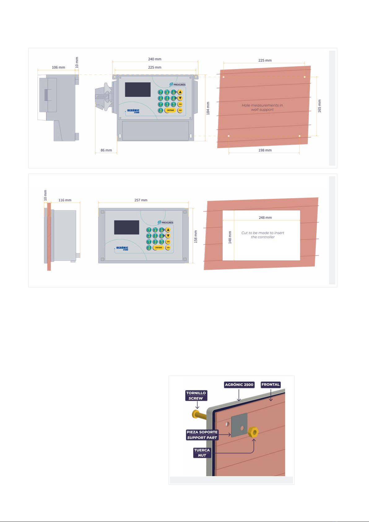
1 DIMENSIONS
Box formatBuilt-in format
Where to install the Agrónic
Install the Agrónic at the correct height and position
for good handling. Avoid direct sunlight, humidity,
dust and vibrations as much as possible.
Avoid being close to elements that generate interfer-
ence and may aect correct operation.
In the box format, the unit is housed in a hermetical-
ly-sealed box (IP65) with a transparent front cover
for the keypad/display and an opaque cover for
housing the connections. The 27-output model uses a
connector attached to the le side of the box.
To maintain the seal, the covers must always be closed
and the cable glands included with the unit installed in
the cable outputs.
Install the unit on the wall with the two perforated
pieces on the top corners and two on the bottom,
removing the connection cover. The fastening
elements can be 4 self-tapping screws (3.5 x 38 mm –
DIN 7981) and 4 6x30 mm plugs (SX 6x30).
In the built-in format, a hole must be drilled in the front
of the cabinet or desk according to the measurements
indicated in the previous drawing and held in place by
the screws on the corners, using the four pieces that
are supplied with the unit (4 M3 x 12 mm screws (DIN
84), 4 M3 nuts (DIN 934) and 4 metal sheets of 20 x 20
x 1 mm).
Assembly

5
Assembly and connection manual | Agrónic 2500
Voltage 12 Vdc +15% -10%
Power consumption Less than 12.5 W (0.3 W in standby)
Fuse Input Thermal (PTC) 1.1 Amp. at 25°C, auto-resettable
General power supply
Voltage From 12 to 24 Vdc or Vac (maximum 30 V)
Fuse Input “R+” Thermal (PTC) 3.0 Amp. at 25°C, auto-resettable
Output power source
Memory Without maintenance, 10 years for parameters, programs and records in memory, in FRAM
memory and records in FLASH memory.
Clock 48 hours without power
Memory and clock safeguard
Digital
Number 9, extendable to 18 and 27.
Type By relay contact, with 24 Vac potential (external transformer).
Limits 30 Vac / 30 Vdc, 1 Ampere, 50-60 Hz, CAT ll (per output)
All outputs have double isolation in respect to the power output.
Outputs
Temperature -5°C to 45°C
Humidity < 85%
Altitude 2000 m
Pollution Grade 2
Environment
Box model From 1.0 kg to 1.6 kg
Built-in model From 1.1 kg to 1.5 kg
Weight
This symbol indicates that electronic devices should not be disposed of along with household waste at the end of their
useful life. The product must be taken to the corresponding collection point for electric and electronic unit recycling and
correctly processed pursuant to Spanish legislation.
Digital sensors Number 6, expandable (option) to 11 on non-Latch models.
Type Opto-coupled, operate at 12 or 24 Vdc or Vac
Analog
(option)
Number 2
Type 4-20 mA, 0-20 V. (on demand, with galvanized separation)
Number 4
Type 4-20 mA
Inputs
Complies with Directive 89/336/EEC for Electromagnetic Compatibility and Low Voltage Directive
73/23/EEC for Product Safety Compliance. Compliance with the following specifications was
demonstrated as indicated in the European Community Oicial Gazette.
Statement of compliance
2 TECHNICAL SPECIFICATIONS
Protective ground
terminal Antenna Ground terminal Double isolation
Symbols that may appear on the product

6Assembly and connection manual | Agrónic 2500
3 CONNECTION LOCATIONS
3.1. BOX FORMAT
In the box format, remove the bottom cover to access
the connectors.
To insert cables, the holes required must be punched
out (do this with the connection cover in place and
screwed in to avoid breaking it).
The 27-output model has the last nine outputs located
in a connector on the le side.
The connectors and antennas from the rest of the
options are located on the right side.
It is recommended to connect the wires to the terminal
using the terminal connectors that come with the unit.
(The terminals accept cables up to 2.5 mm2diameter).
Box format
7
Connection locations | Built-in format
Assembly and connection manual | Agrónic 2500
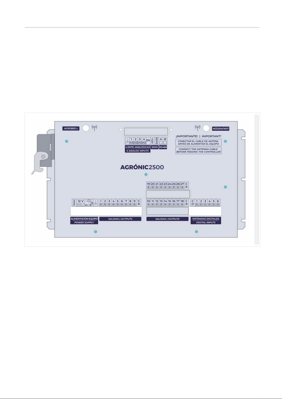
3.2. BUILT-IN FORMAT
To connect the built-in model, access the back park
located inside the desk or cabinet. The connections for
the power supply, inputs and outputs on the 9-, 18- or
27-input models can be found here.
When options are installed, there may also be connec-
tors for the antennas of the AgroBee-L, the modem,
WiFi or radio link option; in addition to the SDI12
expansion option and 4 analog inputs. On the sides,
there may be the USB port connector, the 2 analog
input and the 5 digital input options.
Built-in format
8Assembly and connection manual | Agrónic 2500
4 CONNECTIONS
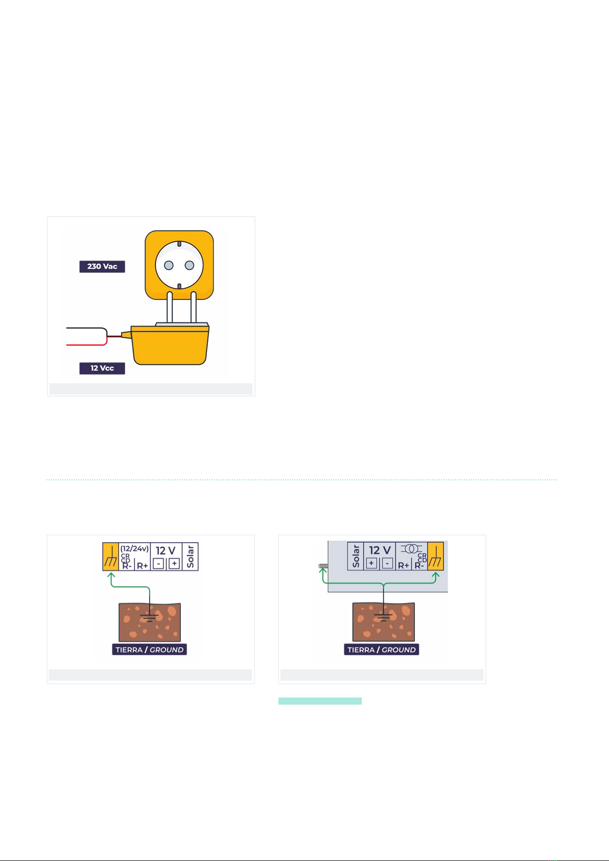
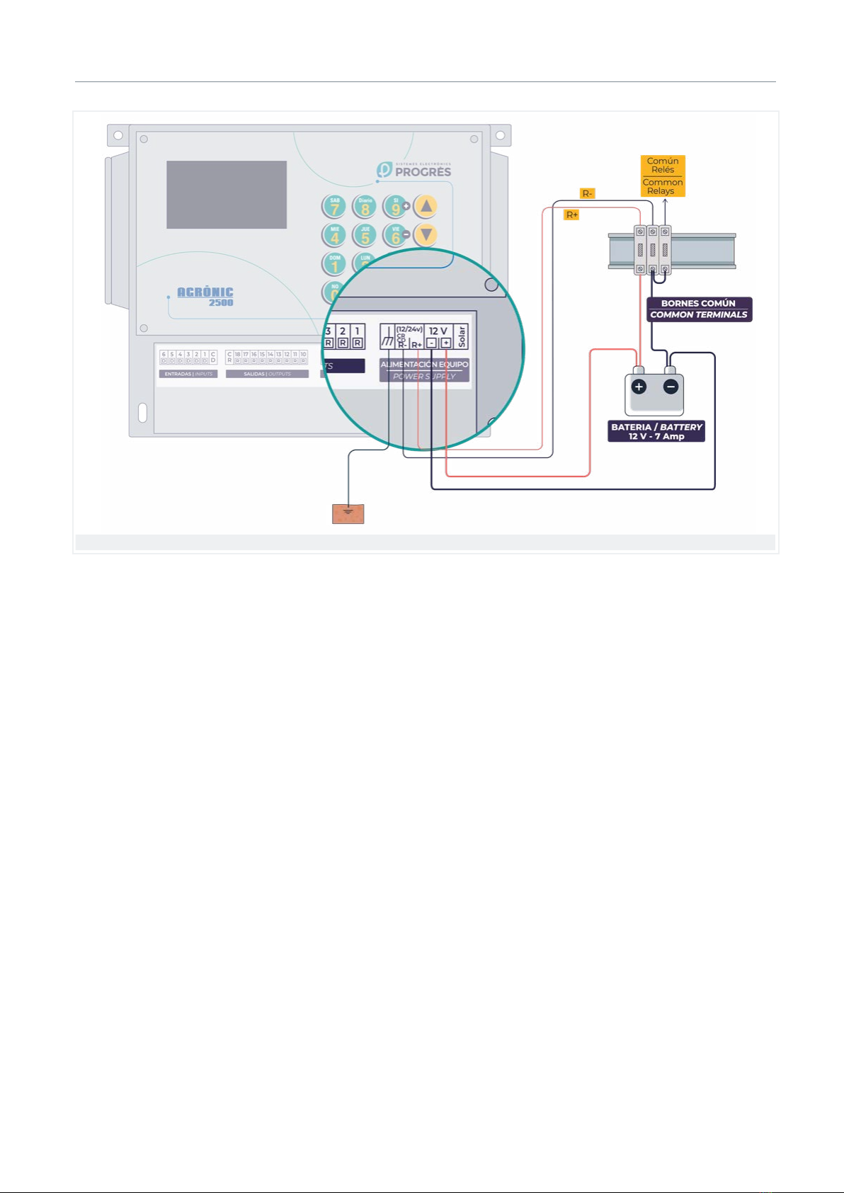
4.1. CONNECTING THE POWER SUPPLY
4.2. CONNECTING THE GROUND CONNECTION
Power
The power supply is 12 Vdc for all models.
Installations with a solar panel, generator set or diesel
pump are connected to the 12 Vdc battery.
The unit must be installed pursuant to the current regulations that apply to electrical installations. The unit will not
be adequately protected if it is not used as specified in this manual.
The Agrónic must be installed away from interference sources such as frequency drives, pumps and power cables.
Sensor and communication cables should never pass next to cables with alternating current and should preferably
be shielded. All the connection terminals on the Agrónic 2500 can be plugged in, which allows for quick maintenance.
In 110 or 230 Vac systems, a 90-230 Vac / 12 Vdc
(50-60 Hz) power supply is available as an accessory
to connect the unit. The socket to which the power
supply is connected must be easily accessible.
The power supply intake has an auto-resetting thermal
fuse and is also protected against reversed polarity
and power surges.
The installation must have a separate thermo-mag-
netic switch to protect the Agrónic 2500. Its output is
connected to the general power supply and the trans-
former that powers the output.
When the diesel pump is running, avoid disconnecting
the battery as the alternator will raise the electrical
tension considerably and damage the Agrónic.
Ground connection in box format
The terminal used for the ground wires is located next
to the power supply terminals; its function is to divert
to the ground any possible electrical sparks generated
by storms that can enter via the input and output
cables. An arc sparkover in the internal gas discharger
is produced with 90 volt or more.
Ground connection in built-in format
It is very important to connect this output inde-
pendently of the rest of the elements within the instal-
lation in order to completely safeguard the unit.
The built-in model has an additional ground connec-
tion on the side of the metal box when it needs to be
diverted to the ground. The ground connection must
be dierent and separate from the ground connection
of drives or pumps.
9
Connections | Connecting digital inputs
Assembly and connection manual | Agrónic 2500
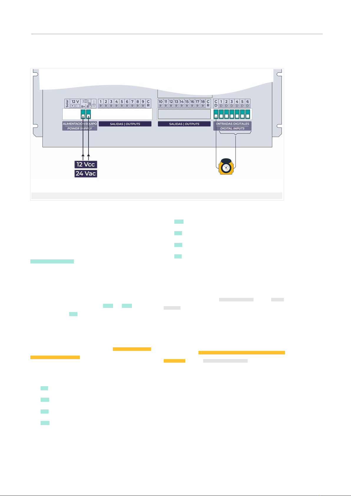
4.3. CONNECTING DIGITAL INPUTS
Both the digital inputs and the relay outputs are
powered externally at 12 Vdc or 24 Vac.
The digital inputs are galvanically isolated by optocou-
plers from the rest of the circuit.
It is very important to know that the contacts of the
units connected to the digital inputs must be volt-
age-free. In other words, when the input is activated,
the common (CD) is internally connected to the input
(Dx).
There are 6 inputs, listed from D1 to D6 , plus a
common marked CD .
In the Basic version
Each of the sensor inputs can take on a function or
operation that is configured in the ‘Function - 4. Pa-
rameters - 3. General’ section of the manual ‘2466
Agrónic 2500 Installer’s Manual Basic Version’.
List of functions:
• IM Irrigation meter
• FM Fertilizing meter
• SC Start cleaning
• TM Temporary malfunction
• DM Definitive malfunction
• CS Conditional stop
• PS Program start
• AL Alarm (Send an SMS message or notification
through Agrónic APP)
In the Plus version
The inputs are assignable to digital sensors or meter
sensors, see sections ‘Digital sensors’ and ‘Meter
sensors’ in the manual ‘2468 Agrónic 2500 Plus Version
Installer’s Manual’.
The functionality of a back-torque filter can be applied
to the meter inputs (IM and FM), in order to avoid false
pulses. By default, the filter is deactivated. It can be
activated from ‘Function - 4. Parameters - 10. Installer -
5. Various’, in the ‘Digital Meter Sensor’ section.
Digital inputs

10 Assembly and connection manual | Agrónic 2500
Connections | Connecting the outputs
24 Vac outputs (220 Vac network installation)
4.4. CONNECTING THE OUTPUTS
4.4.1 Relay output connection
All the outputs are operable at either 12 or 24 volt in al-
ternating or continuous current (do not supply voltage
higher than 30 volt).
To be operative at 24 Vac, an external transform-
er with a double-insulated 24 Vac output must be
installed pursuant to UNE EN61010 standards. There
is an accessory for a 230/24 Vac 50 VA transformer to
connect to the unit.
The power supply intake for the outputs is marked R+
and R- .
The solenoids on the solenoid valves, relays and
contactors are connected between the CR output
common and the corresponding output between R1
and R27 .
The outputs are isolated from the internal circuitry by
relays and protected by a varistor in each one.
The power supplied to the outputs and sensors is
protected by an auto-resettable thermal fuse. The
‘Consultation - Agrónic’ section indicates whether
there is voltage for the outputs or not. When there is
a short circuit in one of the outputs, the fuse will auto-
matically be tripped, limiting the output until the short
circuit has terminated.
11
Connections | Connecting the outputs
Assembly and connection manual | Agrónic 2500
12 Vdc outputs (12 Vdc installation)

12 Assembly and connection manual | Agrónic 2500
Connections | Connecting the outputs
2-Wire latch connections
4.4.2 Connection of latch outputs
In installations where very low power consumption
is needed, latch valves are usually used. The latch
solenoid valve, also called from impulses, functions
by hydraulically locking its open or close position,
consuming power only in the moment it changes
position. This allows power to be powered by a battery
only or by a battery and a solar panel. The calculation
is made taking the installation's options and auxiliary
systems into account.
The installer can configure the unit to use latch
solenoid valves in the two or three-wire format and a
12 or 22-volt trip voltage. See the section ‘Function - 4.
Parameters - Installer’.
If installing 3-wire models, a diode box must be incor-
porated that is appropriate to the total number of the
unit’s outputs, to make the connection from the start
and stop common outputs. This is unnecessary in
2-wire models.
One of the two wires is connected to the CR output
common and the other to the corresponding output
between R1 and R27 .
When the solenoid valve acts hydraulically in reverse
of the order given by the unit, this command will
be reversed by entering ‘Function - 4. Parameters -
Installer - 5. Various’.

13
Connections | Connecting the outputs
Assembly and connection manual | Agrónic 2500
3-Wire latch connections
This solenoid valve model has two commons; the one
for starting (normally red) will be brought to the diode
box, to one of the terminals marked Start ; The stop
common (normally black) is connected to a terminal
marked Stop; the other cable (normally white) is
connected to the corresponding output between R1
and R27 .
The CM start and the CP stop commons must also be
connected on the unit and from the diode box. If the
valve order is the opposite of the desired order, reverse
the Common Start and Common Stop cables.

14 Assembly and connection manual | Agrónic 2500
Connections | Connecting the outputs
When there are electrical units in the installation
(injectors, mixers, pumps, etc.) that must be activated
by Agrónic, a ‘latch relay’ can be used. This unit
converts the Agrónic latch output into an electrical
contact.
Like latch valves, there are two types: 2-wire and 3-wire.
Depending on how Agrónic is configured, it must make
one connection or another. Supports trigger voltage of
12 and 22 Vdc.
2-wire latch relay connection
3-wire latch relay connection
4.4.3 Latch relay connection
15
Assembly and connection manual | Agrónic 2500
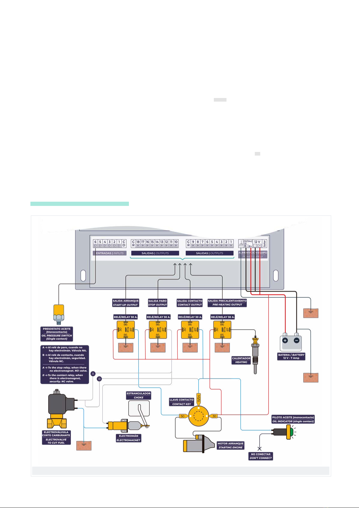
In installations where there is a motor pump, the
Agrónic can manage the start and stop maneuvers. To
manage it, it uses four outputs (preheating, contact,
start and stop) and a digital input (oil pressure gage).
When making the connections for the diesel pumps,
the following details must be taken into account:
INPUTS
PA oil pressure gage. In the version for starting diesel
pumps, the pressure gage input function is assigned to
this input. The CD digital input common does not have
to be connected to the pressure gage as this is done
directly through the pump chassis.
OUTPUTS
The outputs deliver the battery positive. A supple-
mentary relay is intercalated between each to prevent
damage to the internal relays.
The contact output is connected through the relay to
the cable from the ‘15/54’ terminal of the valve. This
is the unit responsible for connecting and disconnect-
ing the contact, so the valve must be le in the inactive
position.
At the start-up output, a supplementary relay is inter-
calated with a capacity for 20 to 30 amperes, connect-
ing the output to the cable from the ‘50’ terminal on
the valve.
If the pump is stopped by an electromagnet, this is
connected to the supplementary relay from the stop
output.
Diesel pump
5 OPTIONS
5.1. DIESEL PUMP CONTROL OPTION

16 Assembly and connection manual | Agrónic 2500
Options | Dual Voltage Option
If the pump is stopped when the fuel supply is cut o
by a solenoid valve, it is installed at the same injector
input for the stop to be as quick as possible. When
the solenoid valve is normally open, it is connected
directly to the stop output. If the solenoid valve is
normally closed, it is connected to the contact output.
When there is a preheating function, this is connected
to the relay to be activated.
For greater safety, it is convenient to have a dual
stopping system that uses an electromagnet for
stopping quickly and eectively, plus a solenoid valve
that is normally closed so as to cut o the fuel supply if
there is an incident or malfunction.
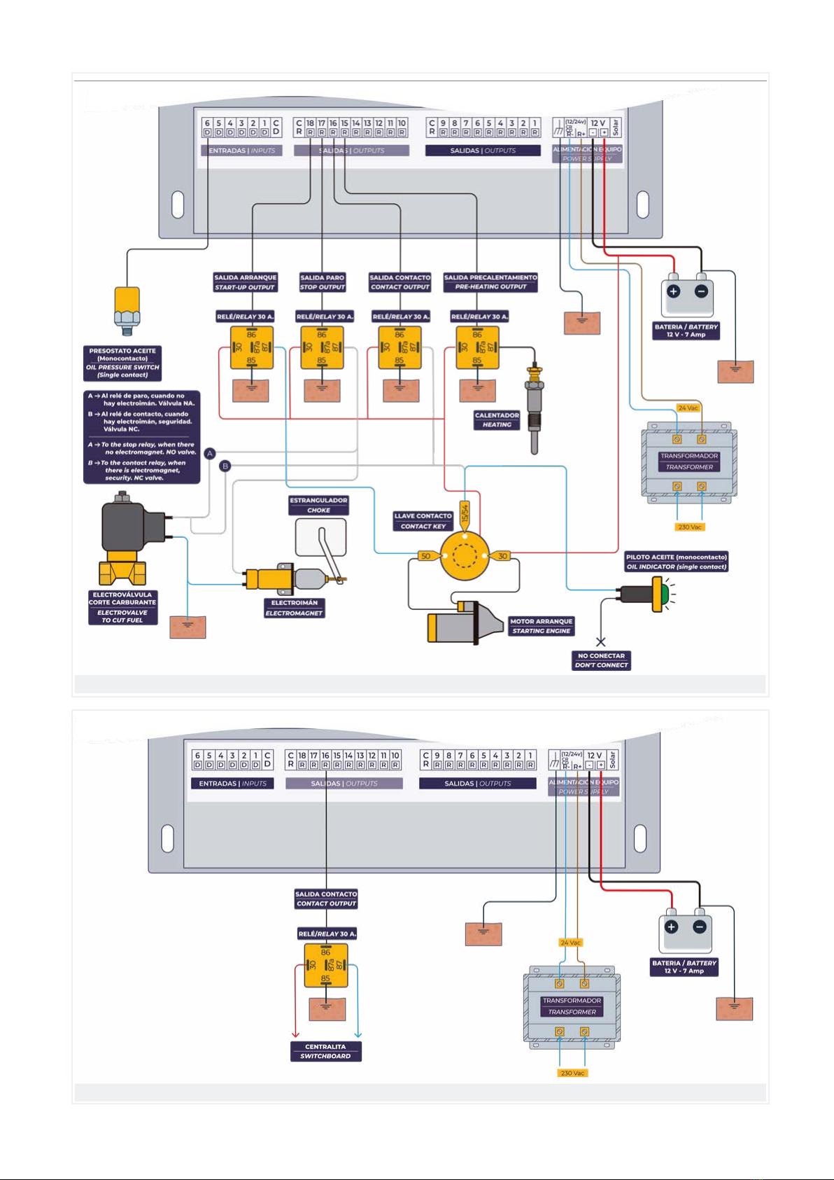
5.2. DUAL VOLTAGE OPTION
The Dual Voltage option is for installations where the
power comes from a diesel generator. The Agrónic will
start the generator when it has to irrigate and will stop
it when finished.
The Agrónic is powered by the group’s 12 Vdc battery.
The four outputs that give the commands to start and
stop the generator go to 12 Vdc, all the others go to 24
Vac and are operational when the generator is running.
The 12 Vdc outputs are always the last 4 of the unit.
The Agrónic can have two functions:
With start and stop management of the diesel pump.
In this case, the diesel pump control is used with the
preheating, contact, start, stop outputs and the digital
input of the oil pressure gage.
With central control start management built into the
generator. In this case, only a contact signal is needed.
To activate this operation, the start and stop times will
be ‘0’.
Agrónic 2500 – 9 outputs 9 8 7 6
Agrónic 2500 – 18 outputs 18 17 16 15
Agrónic 2500 – 27 outputs 27 26 25 24
Electric pump (Pump output M1)
Model Start Stop Contact Preheating
12 Vdc outputs
Outputs at 24 Vac
17
Options | Dual Voltage Option
Assembly and connection manual | Agrónic 2500
Diesel pump with generator set with control unit
Diesel pump with generator set without control unit

18 Assembly and connection manual | Agrónic 2500
Options | Option 2 analog inputs
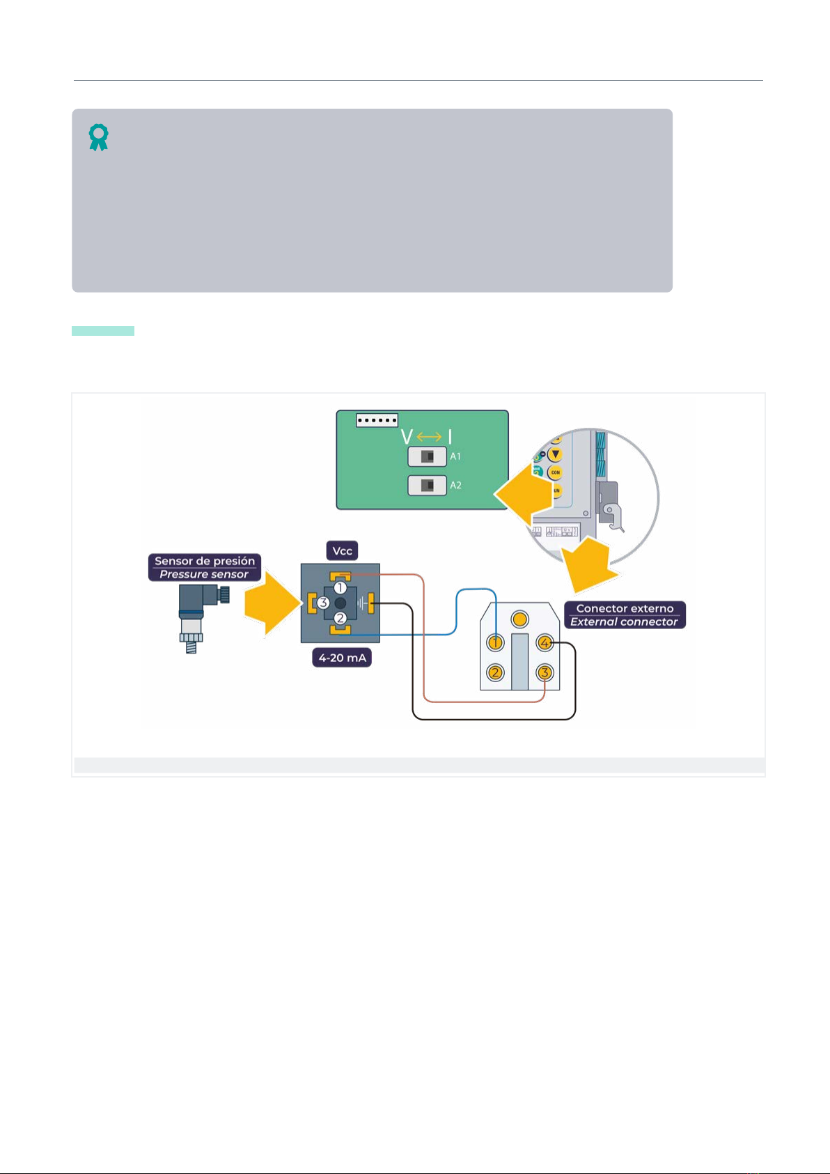
5.3. OPTION 2 ANALOG INPUTS
Only for the Plus version. This option allows up to two
analog sensors to be connected in order to measure
dierent magnitudes (pressure, solar radiation, soil
moisture content, temperature, etc.). A record is made
of the sensors every 10 minutes that can be queried
from the VEGGA / Agrónic APP / Agrónic PC platforms.
It allows the sensors to make measurements, gener-
ating electrical current from 0/4 to 20 mA or voltages
between 0 and 20 volt..
Connection of 2 analog sensors
The wiring in this option has one switch per sensor to
select the measurement using current or voltage. The
default is current, ‘ I ’ position, to select voltage, set it
to the ‘ V ’ position.
The wiring is housed behind the keypad. The location
to connect the sensors must be indicated in ‘Function -
4. Parameters - Installer’.
Terminal 1 Sensor cable A1
Terminal 2 Sensor cable A2
Terminal 3 It corresponds to the output cable for powering the sensors, 12 Vdc, 200 mA.
Terminal 4 Common for the sensor inputs and common for the power supply output (0 V).
Function
Connection of 2 Agrónic 2500 analog inputs
19
Options | Option 2 analog inputs
Assembly and connection manual | Agrónic 2500
IMPORTANT The sensor cables must be shielded and
run separately from cables with alternating current.
Connection example
Examples
• Independent power supply output: Connect the common from the sensor to terminal 4 and t he sensor
signal to terminal 1 or 2.
• Sensor powered by the Agrónic: Connect the common from the sensor to terminal 4, the sensor signal to
terminal 1 or 2 and the power supply positive to terminal 3.
• Sensor with only positive and return: Connect the positive to terminal 3 and the return to terminal 1 or 2.

20 Assembly and connection manual | Agrónic 2500
Options | SDI-12 expansion option and 4 analog inputs
5.4. SDI-12 EXPANSION OPTION AND 4 ANALOG INPUTS
Only with the PLUS version. This option allows you to
connect up to 4 4-20 mA sensors, on terminals A2-1 to
A2-4 and several multi-sensors that communicate with
the SDI-12 bus, on terminal SDI-12.
There is a complete list of the multi-sensors in the
manual ‘2246 Manual Agrónic option SDI12’.
In the built-in format, the connections are located on
the back and in the box format, there are two connec-
This option has an installation manual ‘2196 SDI12 option installation + 4 Agrónic 2500 analog inputs’.
tors on the right side of the unit.
IMPORTANT The sensor cables and the SDI-12 must be
shielded and routed separately from AC cables.
Common, 0 V 0 V Brown
Multi-sensor power supply, +12 Vdc + 12 Vdc Blue
Multi-sensor digital output SDI-12 Yellow / Green
SDI-12 BUS Built-in model terminals Box model cable colors
Common, 0 V 0 V White
Sensor supply, +12 Vdc + 12 Vdc Brown
Sensor A2-1 A2-1 Green
Sensor A2-2 A2-2 Yellow
Sensor A2-3 A2-3 Grey
Sensor A2-4 A2-4 Pink
ANALOG SENSORS Built-in model terminals Box model cable colors
Example of 4-20 mA and SDI-12 sensors
Other manuals for AGRONIC 2500
3
Table of contents
Other Progres Industrial Equipment manuals


Popular Industrial Equipment manuals by other brands


Atlas Copco
Atlas Copco FlexiROC T20 R Operator instructions

Nexen
Nexen AIR CHAMP FW user manual

Camlogic
Camlogic MN-03 Installation and Maintenance

Tronair
Tronair 01-0597-0000 Operation & service manual

Gunnebo
Gunnebo Wedge K12 Additional Installation, Operation and Maintenance Instructions

WPG
WPG MRTA4LP6FACS operating instructions

Thomas
Thomas TRAD 350 SO DIGIT Use and maintenance manual

DYNAMICS GROUP
DYNAMICS GROUP Dings 60 Series instructions

Grundfos
Grundfos Control DC Safety instructions and other important information

Parker
Parker ES2000 Series user guide

ABB
ABB HT611401 Operation manual

SCHUNK
SCHUNK ELM Series Assembly and operating manual