Progres diesel controll 100 User manual
1
INSTRUCTION
MANUAL
INDICE
Sec. THEME Page
1. FUNCIONAL DESCRIPCION 1
2. TECHNICAL CARACTHERISTICS 3
3. INSTALLATION 3
3.1. Wall mounting 3
3.2. Connections 3
3.3. Inputs 3
3.4. Activation by external order 4
3.5. Outlets 4
3.6. Supplementary relays 5
3.7. Option with preheating 5
3.8. Option for petrol engines 5
3.9. Option start-up of electric
generator for net failure detection
6
3.10. Miscellaneous notes 6
4. BREAKDOWN GUIDE 6
5.
CONNECTION SCHEME OF
MISCELLANEOUS OPTIONS 7
PRESENTATION
We wish to express our thanks for the confidence
in us which you have demonstrated by your interest in
our purchase of the DIESEL-CONTROL 100.
For us, this confidence inspires us to work harder
every day to deserve it, and thus, to justify the tradition
of quality which our products have.
This manual will allow you to see the capacity of
the unit as well as its installation and use.
However, if any doubts should remain, let us know
and we will happy attend to them.
1. FUNCIONAL DESCRIPTION
This is an electronic unit for the automatic
starting and stopping of diesel and petrol engines,
with breakdown detection.
STARTING
Starting can be carried out:
a) By means of a programmable clock which
can be built into the unit.
b) By signals from external elements (level
sensors, another programmer, etc.).
c) Manually ( “MANUAL START” button).
The activation time of the starter motor can be
adjusted between 1 and 12 seconds (“START”
button).
In case of a failure in the starting, the unit will
make up to 4 attempts, with 2 minute pauses between
them. If all attempts fail, there is an illuminated
indicator which warns of the occurrence (“START
FAIL”).
The unit will detect the starter failure by means
of the oil pressure.
There is a illuminated warning light for engine
working order (“WORKING”).
STARTER FUNCTIONING THEORY
On receiving a start order, be it from the builtin
clock, the manual start or external elements, the unit
activates the starter relay for the prefixed time set by
the corresponding adjustment. On finishing, it waits
for 1 and a half minutes to detect the working of the
engine through the oil pressure.
If it has failed to start, it will carry out up to 4
attempts, separated by a fixed timing of two minutes.
If all these attempts fail to start the engine, the
“START FAIL” indicator will be activated
The contact relay and the “WORKING” indicator
remain activated from start to stop.
If the engine is working and the pressure gauge
input is disconnected, the unit not obey start orders.
There is a CONTACT outlet which remains
2
activated from when the first attempt at starting is
made until the stop.
An electrovalve for irrigation can also be
connected to the contact outlet.
Optionally, the unit can be supplied with a
warm-up function. In this case, it will have a button for
programming the warm-up timing on the front, which
will function before the activation of the starter motor.
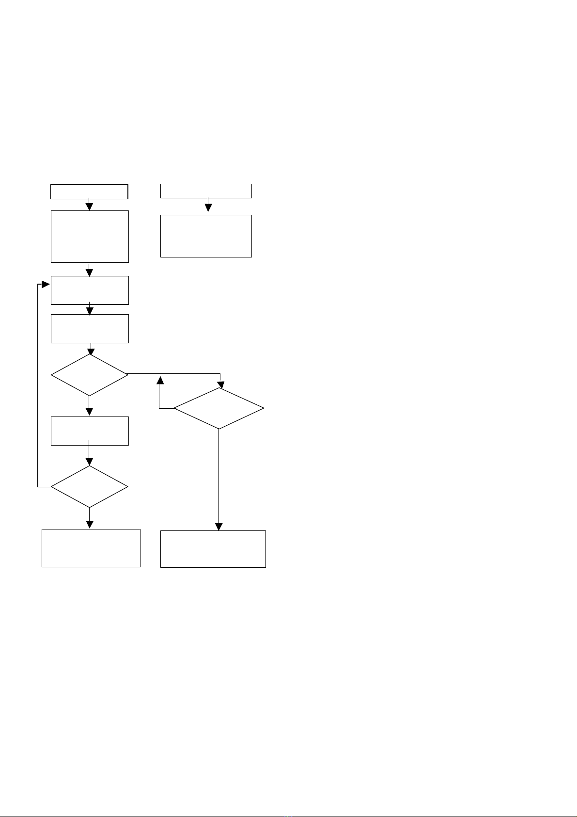
FUNCTION DIAGRAM
STOP
The stop can be caused:
a) By the end of the timing programmed on
the clock.
b) By obeying external elements such as,
for example, level sensors, irrigation
programmers, etc.
c) Manually (“MANUAL STOP” button).
d) By the detection of a breakdown by a
sensor connected to the corresponding
input (motor overheating, oil pressure,
lack of water, etc.), this being recorded
by the illuminated indicators (“SENSOR
BREAKDOWN”).
STOP FUNCTION THEORY
The stop is carried out by the activation of an
outlet, for a short period of time, which can be
connected to an electro-valve (cut in the fuel supply)
or an electro-magnet (choking the engine).
It is advisable to mount the electro-valve, for the
stop, on the engine, between the filter and the injector.
Stop time is adjustable from 6 to 90 seconds
(“STOP” button).
The setting for the stop timing should be left at
least 30 % longer than the time the engine actually
takes to stop.
BREAKDOWN DETECTION
Breakdowns will only be detected from one and
a half minutes after the engine has actually started.
On detecting a breakdown through the sensors
or in the oil pressure, the unit will automatically
activate the stop relay, also keeping the “SENSOR
BREAKDOWN” indicator lit although the breakdown
disappears. This will only go out on restarting. engine
again. However, if the breakdown continues, the unit
stop the
OPTIONS
WITHOUT CLOCK. In this option, the unit
incorporates a start/stop input for possible connection
to programmers or other external elements.
WITH ONE DAY CLOCK, which repeats the
programmes every day. In this option, 15 minute
intervals between orders are possible.
WITH WEEKLY CLOCK, which repeats the
programmes daily or weekly.
In this model, the intervals between orders are two-
hourly.
WITH DOUBLE SPHERE CLOCK, which repeats
the programmes daily or weekly, as in the “WEEKLY”
version, but with 30 minute intervals between orders.
WITH DOUBLE OUTLET DIGITAL CLOCK,
which allows orders by minutes and with daily or
weekly frequency. It has 2 outlets for, per example,
working with two different irrigation sectors, or with
only one but with independent fertilizer application.
WITH PRE-HEATING. With this option, the unit
preheats the engine before each attempt at starting.
CLOCK
The Diesel Control can incorporate different
kinds of clocks. If they are digital, moreover of this
manual, there is one about the clock. If they are
analogical (of gantries) you can follow these
instructions:
ACTIVATION STOP
RELAY.
DEACTIVATION OF
WORKING INDICATOR
STOP
WORKING
STARTER TIMING
ACTIVATION
CONTACT AND
WORKING
INDICATOR: 1ST
START ATTEMPT
1 ½ MINUTE WAIT
MOTOR HAS
STARTED
1 ½ MINUTE WAIT
IS IT THE
4TH
ATTEMP
T
ACTIVATION OF
STARTER BREAKDOWN
INDICATOR
BREAKDOWN
ACTIVATION OUTLET
ACTIVATION SENSOR
BREAKDOWN INDICATOR
SI
YES
NO
NO
NO
YES
3
PROGRAMATION
Adapt the gantries of programming moving
them out (for the time that you want the engine to be
active) or pressing to put them in.
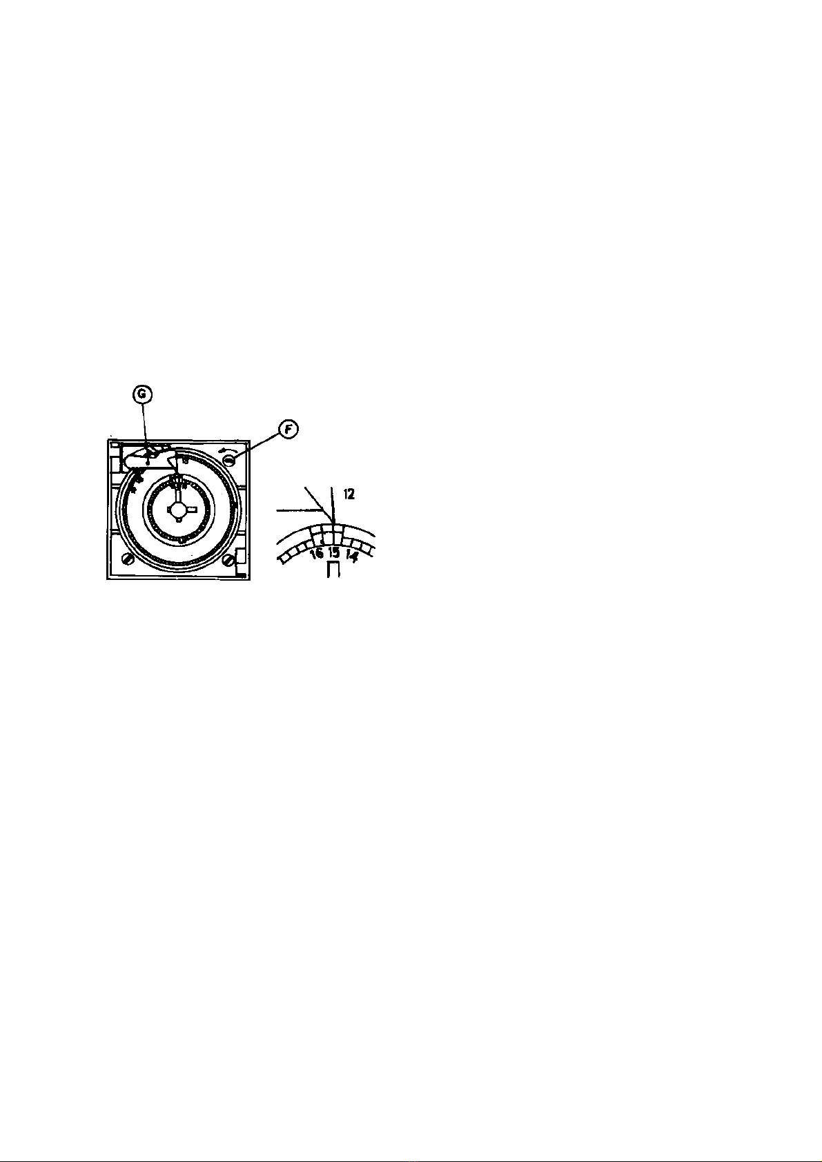
SETTING IN TIME
Use the command “F” of working of spheres
and pointers, avoiding moving them directly. For the
setting in time, consider the index of operations “G” as
much as the pointers; thus, if we want to select 15
hours, the index of operations “G” should have to
indicate 15,00 and the pointers should be at the
position that the figure indicates.
In the double sphere clocks, have to be
programmed the internal and the external sphere.
WARRANTY
The unit is warranted against manufacturing
defects for two years.
Breakdowns caused by accidents, mis-
connection and unauthorised use are excluded from
this warranty.
2. TECHNICAL CHARACTERISTICS
PROTECTION
Protection against polarity changes in the feed
input.Protection against power surges.
Protection against the chance activation of the
starter when the engine is working.
UNIT CONSUMPTION
Stopped 0.0025 A (0,03 W).
Working 0,0600 A (0,70 W).
PERMITTED WORKING TEMPERATURES
From -5 º C to +45 º C.
COMPONENTS
C-MOS integrated circuits. 10 A relay outlet.
MOUNTING BOX
Metal with lock, 25x25x8.
3. INSTALLATION
3.1. WALL MOUNTING
4 pieces for wall mounting are supplied with the
unit, which are mounted, from the outside and without
need to open the unit, in the holes on the back of this.
Site the engine, battery and DIESEL-CONTROL
as close as possible to each other, bearing in mind
possible problems which might arise such as, for
example, a water leak from the pump wetting the unit,
engine vibrations, etc...
3.2. CONNECTIONS
To connect the unit, remove the “connection
housing” cover.
3.3. INPUTS
Feed the unit 12v DC (INPUT terminals 7 and 8)
respecting the polarity.
The connection should be made with 2.5 mm2
cross-section cables, with direct feed from the battery
terminals, without any other connection between these
two points.
On connecting the unit to the battery, wait about
3 minutes before beginning any working operation. If
any warning light stays lit, press the MANUAL STOP
button and the unit will be prepared to initiate the
starter sequence.
Input no. 5 (STARTER DETECTOR) must be
connected directly to the oil pressure gauge,
prescinding any other connection (for example, the oil
warning light). To make the connection, first
disconnect the pressure gauge and do not reconnect
it as, if not, the unit could be damaged. The cable
cross-section should be 1.5 mm2.
When the unit does not obey start orders, it will

4
normally be because of the oil pressure gauge, given
that if it fails to receive a signal from this gauge, the
unit will understand that the engine is already working.
3.4. ACTIVATION BY EXTERNAL ORDER
When the Diesel-Control is delivered without
clock, and thus, is destined for activation by other
units, it will dispose of an input (terminals 1 and 2) for
these.
In this case it will be necessary to leave the
outlet to be used by these external units free of
tension.
The Diesel-Control, on receiving a signal will
initiate the start and when the signal ceases it will
activate the stop. Because of this, it will keep the
engine activated while there is a contact on inputs 1
and 2.
Even when the unitincludes a clock, it can carry
out starts and stops obeying level sensors, or similar,
by way of inputs 2, 3 and 4. (External signals always
free of tension). In these inputs the cables can be of 1
or 1.5 mm2 cross-section.
These inputs, differently from number 1 and 2
before, are independent for starts and stops and,
furthermore, only function with the initial impulse of a
signal or contact.
There use will be useful when the start has to be
by clock and the stop by level indicator (inputs 2 and
4); or when the activation is by sensor (inputs 2 and 3)
and the stop by clock; or when their is external
activation and deactivation by way of differentiated
impulses for start and stop.
In input 6 (breakdown) any kind of sensor with a
normally open contact, free of tension can be
connected. The cross-section of the cable can also be
either 1 or 1.5 mm2.
3.5. OUTLETS
Terminal no. 1 (common outlet) must be
connected directly to the positive battery terminal. The
cross-section of this cable can be 2.5 mm2.
The outlet for activating the starter motor
(terminal 2) has a relay with a maximum intensity of
10ª (as have the remaining outlets).
However, it is necessary to install a
supplementary relay between this outlet and the
starter motor. Follow the instructions which appear
later. This terminal has to be connected to one pole
of the supplementary starter relay winding. The other
pole has to be connected directly to the negative.
These cables can be of 1.5 mm2 cross-section.
The starter relay common outlet must be
connected directly to the positive with a direct 6 or 8
mm2 wire. The other contact must be connected to
the distributor with a similar wire.
There are engines which need to work with
double injection by way of a small electro-magnet
which will be connected in parallel with the starter.
The stop outlet (terminal 3) can act directly
without a relay in between, through an electro-valve
(which will temporarily cut the fuel supply) with a
1.5mm2 cable.
The stop electro-valve will be installed between
the filter and as close as possible to the injector input
and will normally be open and at 12v DC.
The engine can also be stopped by way of an
electro-magnet (which chokes the engine).
If the electro-magnet system is chosen, a
supplementary relay must be installed. The
connecting up of the Diesel-control and the relay and
that of this to the electro-magnet will be carried out in
the same way as in the case of the start. It being
possible to bridge the negatives of the relay windings
and the positives of the common outlets of the
contacts, with the same sections as specified above.
The contact outlet (terminal no. 4 will remain
activated from the moment of starting until the stop.
The contact outlet gives positive whenever the
unit is working (“WORKING” LED illuminated). This
outlet will only be used in case we need to activate a
general aperture electro-valve, or when the engine
needs the contact signal to charge the battery.
In this case it can be connected directly to the
contact position of the starter key.
At the contact outlet, an electro-valve for
irrigation can be connected if necessary.
Use 35 mm2 cross-section cable as normally
used in the motor industry from the battery negative to
the engine chassis. This section should be increased if
the distance between the battery and the engine is
greater than 3 metres.
The connection to the engine or the support
must be good. An adequate place could be where the
rectifier negative connects to the earth 9.
The cable from the positive to the starter motor
terminal should have a cross-section of 20 mm2, for a
distance not greater than 4 metres, so that the tension
drop on starting the engine is minimum; this way the
battery charge will also be used to its maximum by the
alternator.
For the connection of Diesel-control, it would be
convenient if all the cables had terminals, by which a
greater degree of security and a better appearance
would be achieved in the connections, thus also
avoiding poor connections which occasionally causes
false contacts.
Avoid producing short-circuits in the cables
given that the unit does not contain fuses (to avoid
tension drops in the same).
5
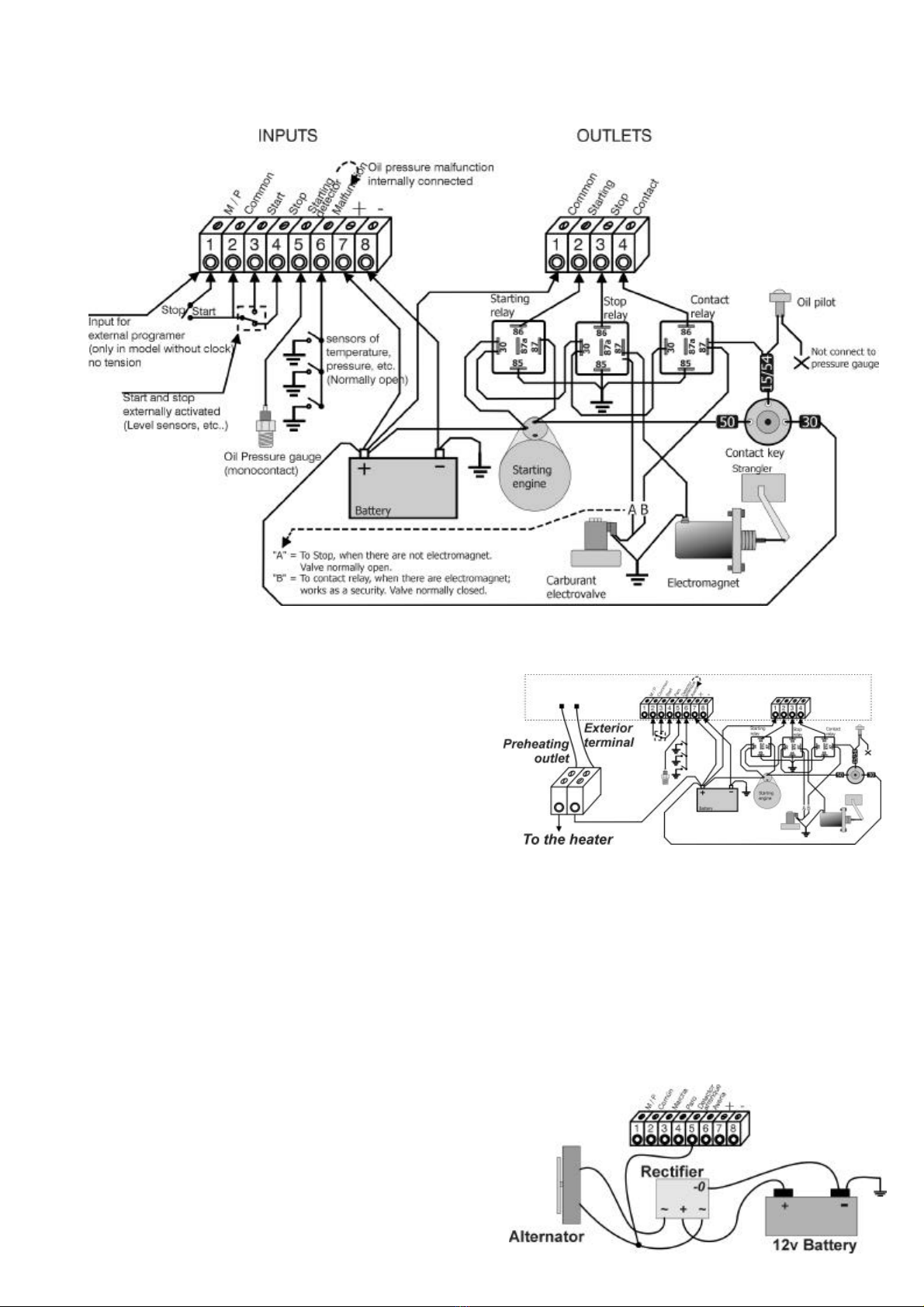
CONNECTIONS SCHEME
3.6. SUPLEMENTARY RELAYS
The supplementary relays on the start and stop
outlets will protect the Diesel-control from possible
anomalies from problems arising from the high power
which the distributor or electro-magnet needs for its
correct working.
The relays used will be 12v, with a shorting
capacity of 20 or 30ª. These relays are the type usually
used in the motor industry.
The supplementary relays can be placed inside
a sealed box of the type used in electrical installations,
which will be mounted as close as possible to the
engine.
The cables (1.5 mm2 sections) which govern
the supplementary relays will come out of terminals 2
and 3 (start and stop). These cables carry the positive
to the pole of the winding.
3.7. OPTION WITH PREHEATING
The units delivered with this option incorporate
another button on the frontpiece where the timing (in
seconds), of the preheating to be carried out before
the attempt at starting, can be programmed.
To connect the heater, in the connection housing
there will be a loose terminal which comes from the
positive. Place a relay like those described above
here.
CONNECTIONS SCHEME
3.8. OPTION FOR PETROL ENGINES
Only for the units that they have this option.
In petrol engines, which generally do not have
oil pressure gauges, the detection of the start is
determined by the moment when the alternator begins
to generate electrical tension.
For the connection of the unit it is sufficient to
take one of the poles of the alternating current
generated by the alternator to input terminal no.5
before it enters the rectifier. (See the following
diagram).
Table of contents
Other Progres Industrial Equipment manuals


