Leister SEAMTEK W-AT Series User manual

Leister Technologies AG
Galileo-Strasse 10
CH-6056 Kaegiswil, Switzerland
Tel. +41 41 662 74 74
Fax +41 41 662 74 16
www.leister.com
sales@leister.com
SEAMTEK
W-900 AT
W-2000 AT
EN

EN
English Operating instructions 4
Contents
1. SEAMTEK W-AT............................................................................................................................................................ 4
1.1 Using this Manual ............................................................................................................................................... 4
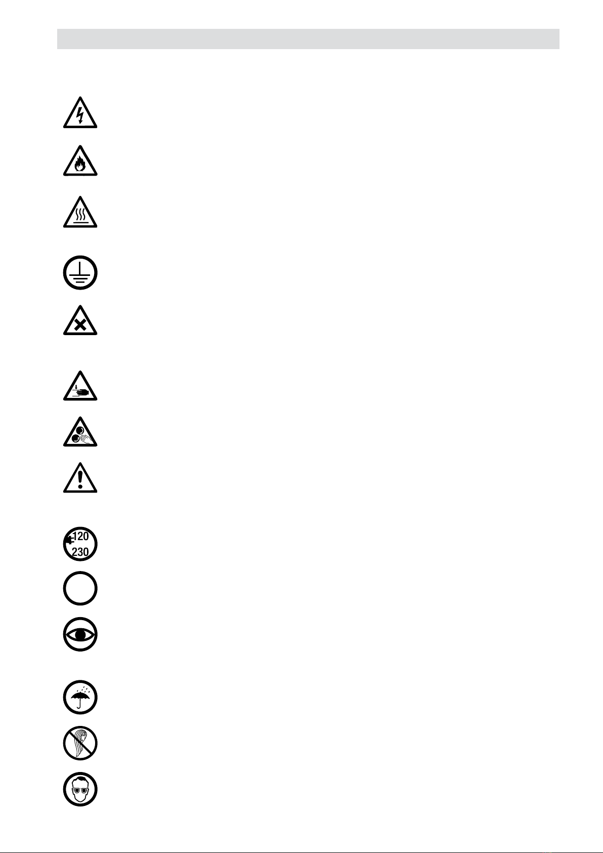
2. Overview of Important Safety Instructions .................................................................................................................. 5
2.1 Important Safety Instructions ............................................................................................................................... 5
2.2 Intended Use ...................................................................................................................................................... 6
2.3 Improper Use...................................................................................................................................................... 6
2.4 Welding Vapors................................................................................................................................................... 6
2.4.1 Extraction ............................................................................................................................................... 6
2.5 Operating Modes ................................................................................................................................................ 6
2.6 Specialists and Training....................................................................................................................................... 6
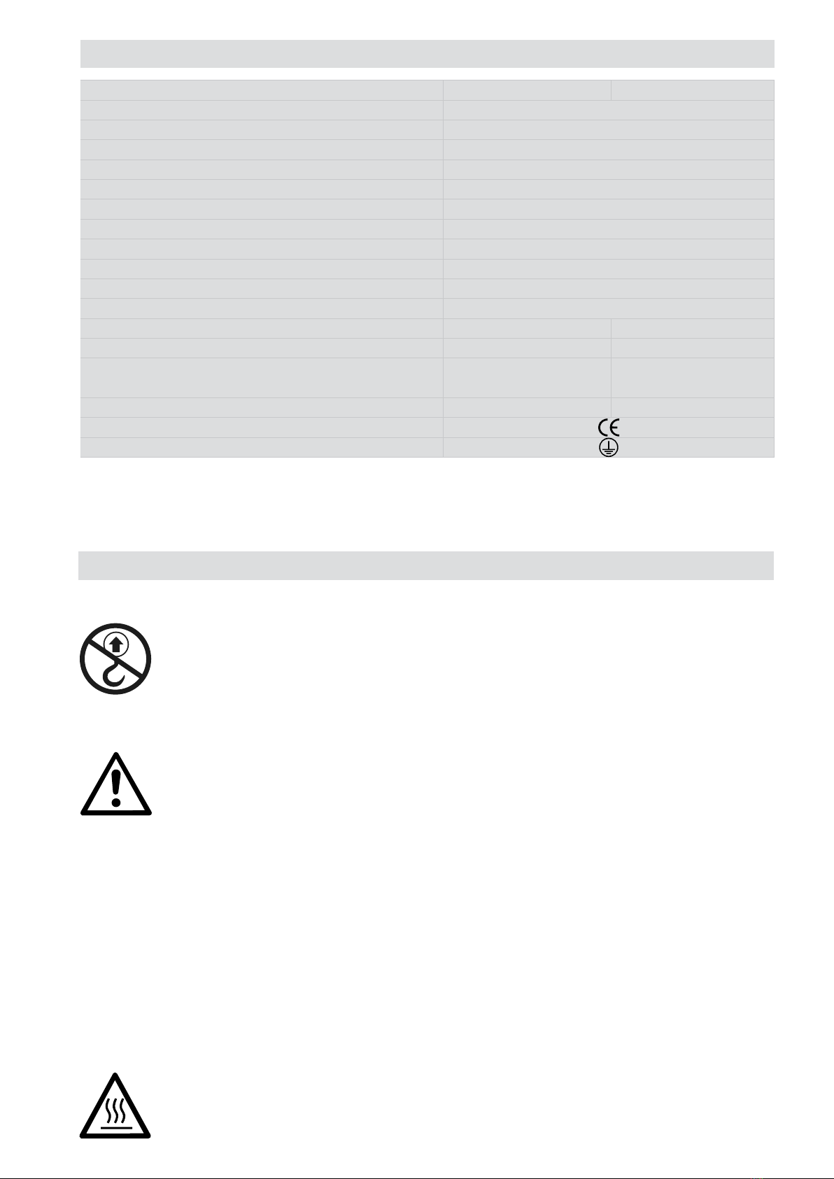
3. Technical Data ............................................................................................................................................................. 7
4. Transport and Commissioning ..................................................................................................................................... 7
4.1 Delivery.............................................................................................................................................................. 7
4.2 Unloading the Machine from the Transport Crate................................................................................................... 7
4.3 Transportation on the Company’s Premises........................................................................................................... 7
4.4 Transportation outside of the Company’s Premises................................................................................................ 8
4.5 Work Environment............................................................................................................................................... 8
4.6 Workplace and Workplace Environment................................................................................................................ 8
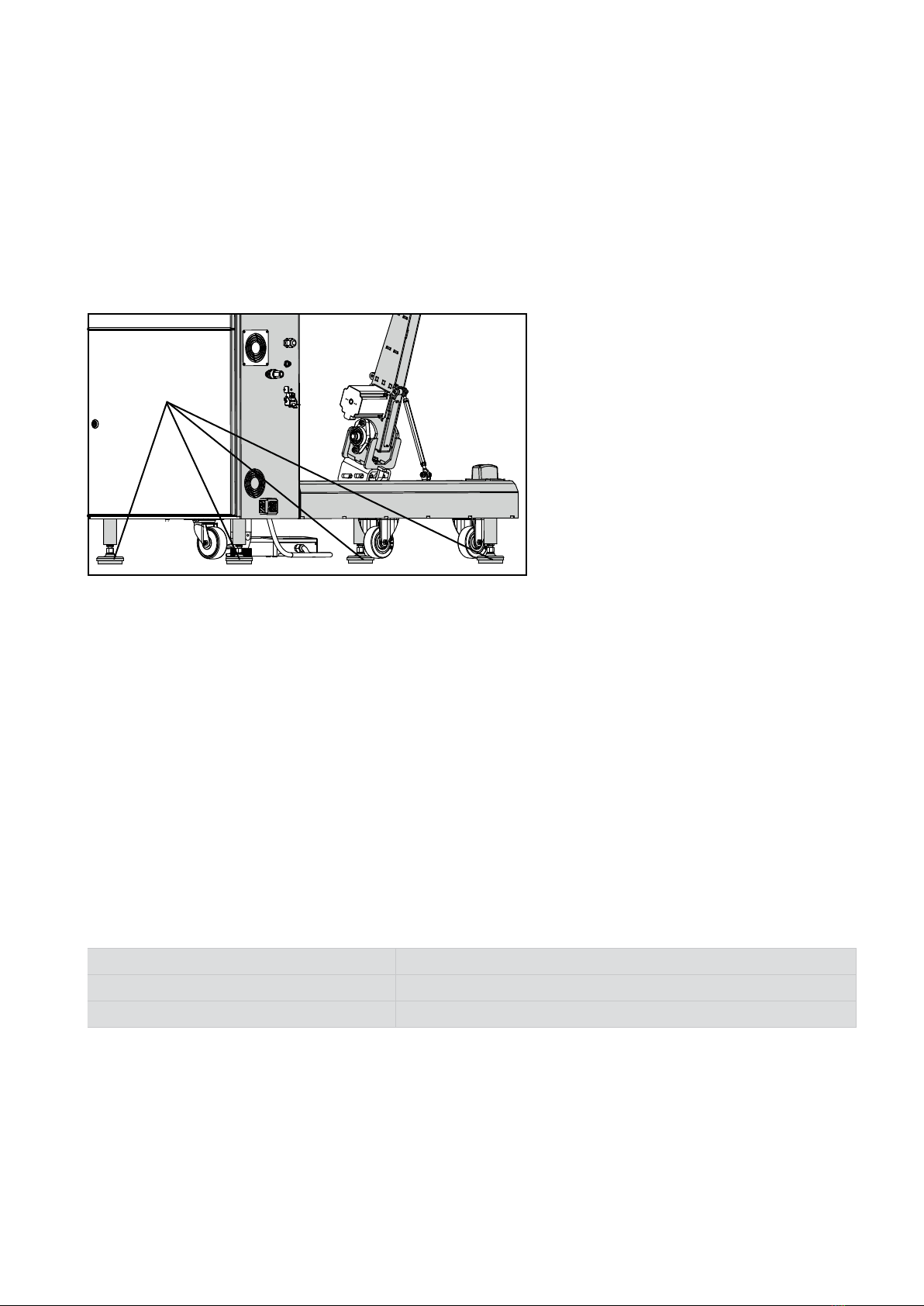
4.7 Securely Positioning the Machine......................................................................................................................... 9
4.8 Commissioning the Machine................................................................................................................................ 9
4.8.1 Power Supply.......................................................................................................................................... 9
5. Your SEAMTEK W-AT.................................................................................................................................................. 10
5.1 Type Plate and Identification .............................................................................................................................. 10
5.2 Scope of Delivery (standard model in transport box) ............................................................................................ 10
6. Overview of Machine Elements ................................................................................................................................. 11
6.1 Front View ........................................................................................................................................................ 11
6.2 Back View ........................................................................................................................................................ 12
6.3 Switch Cabinet.................................................................................................................................................. 12
6.4 Outlets for Accessories...................................................................................................................................... 12
6.5 Optional Accessories......................................................................................................................................... 13
6.5.1 Quickarm.............................................................................................................................................. 13
6.5.2 Tape Delivery System ............................................................................................................................ 13
7. Operation and Operating Elements............................................................................................................................ 13
7.1 Hot-Wedge Holder............................................................................................................................................. 13
7.2 Air Outlet for Switch Cabinet Cooling.................................................................................................................. 14
7.3 Touch Panel Operating Unit................................................................................................................................ 14
7.4 Emergency Stop Button ..................................................................................................................................... 14
7.4.1 Emergency Stop Button Function............................................................................................................ 15
7.5 USB Connection................................................................................................................................................ 15
7.6 Main Switch ..................................................................................................................................................... 15
7.7 Feet ................................................................................................................................................................. 16
7.8 Pedal Unit......................................................................................................................................................... 16
7.9 Changing Welding Arm and Welding Arm Options ............................................................................................... 17
7.9.1 Changing Welding Arm.......................................................................................................................... 17
7.9.2 Pedestal ............................................................................................................................................... 17
7.9.3 Quickarm.............................................................................................................................................. 18
7.10 Transport Rollers............................................................................................................................................... 18
7.10.1 Changing the Transport Rollers............................................................................................................... 19
7.11 Guide Holder..................................................................................................................................................... 20

7.11.1 Mounting and Adjusting the Guide.......................................................................................................... 20
8. Hot Wedge ................................................................................................................................................................. 21
8.1 Wedge Types.................................................................................................................................................... 21
8.1.1 3D Wedge (3-Dimensional Wedge)......................................................................................................... 21
8.1.2 HS Wedge (High-Speed Wedge) ............................................................................................................. 21
8.2 Wedge Cleaning................................................................................................................................................ 22
8.3 Changing the Wedge Holder / Changing the Welding Width ................................................................................. 22
8.4 Adjusting the Welding Wedge Height.................................................................................................................. 23
8.5 Changing the Wedge......................................................................................................................................... 23
9. SEAMTEK W-AT Touch Panel Operating Unit.............................................................................................................. 24
9.1 Start Screen ..................................................................................................................................................... 24
9.2 Home Screen.................................................................................................................................................... 24
9.2.1 Tab for Changing Views ......................................................................................................................... 25
9.2.2 Welding Parameters .............................................................................................................................. 26
9.2.3 Periphery.............................................................................................................................................. 27
9.3 User Tab........................................................................................................................................................... 28
9.4 Settings Tab...................................................................................................................................................... 30
9.5 Recipe Tab ....................................................................................................................................................... 31
9.6 Wedge Tab ....................................................................................................................................................... 32
9.6.1 Safety Instructions................................................................................................................................. 32
9.6.2 Wedge Adjustment Wizard..................................................................................................................... 32
9.6.3 Changing the Welding Wedge ................................................................................................................ 33
9.6.4 Positioning the Welding Wedge .............................................................................................................. 35
9.7 Accessories Tab................................................................................................................................................ 38
9.8 Information Tab................................................................................................................................................. 38
10. Welding Sequence and Tips .................................................................................................................................... 39
10.1 Welding Sequence ............................................................................................................................................ 39
10.2 Tips for a Better Weld Result ............................................................................................................................. 39
11. SEAMTEK W-AT Warning and Error Messages......................................................................................................... 40
11.1 Error Levels ...................................................................................................................................................... 40
11.2 Error List .......................................................................................................................................................... 40
12. Maintenance............................................................................................................................................................ 44
12.1 Maintenance Intervals ....................................................................................................................................... 44
12.2 Replacing the Suction Filter .............................................................................................................................. 45
12.3 Machine Fault................................................................................................................................................... 45
12.4 Adjusting the Welding Arms .............................................................................................................................. 45
13. Accessories ............................................................................................................................................................. 46
14. Add-ons ................................................................................................................................................................... 46
15. Service and Repair .................................................................................................................................................. 46
16. Training.................................................................................................................................................................... 46
17. Warranty ................................................................................................................................................................. 46
18. Disposal................................................................................................................................................................... 46
19. Quick Reference Guide ............................................................................................................................................ 46
19.1 Switching on/Starting ........................................................................................................................................ 46
19.2 Switching o .................................................................................................................................................... 46
20. Declaration of conformity ........................................................................................................................................ 47

4
Operating instructions (translation of original operating instructions)
EN
Leister SEAMTEK W-AT
Welding machine
Read through the operating instructions before commissioning
for the first time. Always store these operating instructions with the device.
Do not pass the device on to anyone else without the operating instructions.
Thank you for purchasing this first-class hot-wedge welding machine from Leister. The SEAMTEK W-AT is a comput-
er-controlled hot-wedge welding machine that is used for joining laminated industrial textiles, e.g., polyvinyl chloride
(PVC), polyurethane (PU), polyethylene (PE), and polypropylene (PP). Today, these industrial textiles are used for a mul-
titude of important and interesting products, including 3D applications, tents, tarpaulins, inflatable objects, geomem-
branes, truck tarpaulins, coverings for the agricultural sector, fishing equipment, protective clothing, protective covers,
pipes, synthetic leather, and many more. The possibilities are practically unlimited.
The SEAMTEK W-AT is manufactured by Leister Technologies AG in Kägiswil, Switzerland. These operating instructions
provide detailed explanations of the following:
• Setting up and installing the SEAMTEK W-AT
• All operating sequences
• Description and tasks of the various modules that are available when using your SEAMTEK W-AT
These operating instructions also include a list of troubleshooting tips, warranty information, and a clearly structured
table of contents. Please read through all of the sections in these operating instructions carefully before using your
SEAMTEK W-AT for the first time.
These operating instructions supersede all operating instructions with an earlier date. The older versions no longer ap-
ply. When a new version of the operating instructions is issued, this version will be superseded and will no longer apply.
Leister Technologies AG makes every eort to ensure that the information contained in this manual is complete and
exact. No guarantee, either concrete or implied, is however provided, nor is any liability assumed for the use of this
information with respect to either its completeness or accuracy.
This manual may be updated from time to time without prior notice. The latest version of all operating instructions
published by Leister Technologies AG can be obtained by authorized users upon request to Leister Technologies AG.
1. SEAMTEK W-AT
Congratulations on purchasing your SEAMTEK W-AT.
You have chosen a first-class hot-wedge welding machine.
It was developed and produced in accordance with the latest advances in the plastics-processing industry. It has also
been manufactured using high-quality materials.
1.1 Using this Manual
Two versions of the SEAMTEK W-AT are available. The SEAMTEK W-900AT with 900mm working area and the W-2000AT with
2000mm working area. Unless otherwise noted, all function descriptions, instructions, warnings, cautions and symbols apply for
both versions. The illustrations are based on the SEAMTEK W-900AT, the dimensions may dier for the W-2000AT. In the follow-
ing, the abbreviation SEAMTEK W-AT refers to both versions.

5
2. Overview of Important Safety Instructions
Warning
Danger to life due to high voltage
Before opening the switch cabinet, the device must be disconnected from the power supply at all poles.
(Disconnect the power plug.) Live components and connections may be exposed in the process.
Risk of fire
There is a risk of fire if the welding machine is used improperly (e.g., due to the material overheating),
particularly in the vicinity of flammable materials.
Risk of burning!
Do not touch the hot-wedge holder, hot wedge, and stepping motors when they are hot. Do not wear any
jewelry or watches, particularly on the hands, arms, and fingers. The device should always be allowed
to cool down first.
Connect the device to an outlet with a protective conductor.
Any interruption of the protective conductor inside or outside of the device is dangerous.
Only use extension cables with protective conductors.
Risk of poisoning
Gases are released during the processing of plastics, lacquers, or similar materials that could be aggres-
sive or toxic. Avoid breathing in vapors, even if they seem to be harmless. Make sure the workplace is
well-ventilated at all times or wear a breathing mask.
Risk of crushing
There is a risk of crushing due to the movement of mechanical and/or electromechanical parts. Take the
necessary precautions to prevent hazards posed by mechanical parts.
Risk of entanglement
Avoid reaching between moving parts such as the transport rollers in order to prevent objects or body
parts becoming entangled.
Two people are needed to move the machine. Make sure that the machine cannot topple over.
Caution
The nominal voltage specified on the device must match the local line voltage. If the supply voltage
fails, the main switch and the drive must be switched o.
RCD When using the device, a residual-current circuit breaker is required to protect the personnel working
at the site where the device is being used.
The device must be supervised at all times during operation. Waste heat can come into contact with
flammable materials that are not in view.
Device may be operated only by trained specialists or under their supervision. Children are not permit-
ted to operate the device under any circumstances.
Protect the device from moisture and wet conditions.
When working on the open system, do not wear such articles of clothing as scarves, shawls, or neck-
ties. Tie up long hair or protect it by wearing headgear.
Wear protective goggles
In certain processes, various metal parts and materials are heated to high temperatures and can produce
splashes if handled incorrectly. Operating sta and persons in the immediate vicinity of the device must
therefore wear protective goggles.
2.1 Important Safety Instructions

6
Make sure to use the correct welding parameters. When redetermining the welding parameters, start with a low energy
value and increase it until you achieve a good weld result. This will ensure that the weld materials are not burned and
will reduce welding vapors. As an accessory, Leister oers an adapter for the SEAMTEK W-AT, which can easily be
mounted on an external vacuum device. Please ask your distribution partner about this.
The vacuum device (Leister accessory 155.410) is supplied without an extraction unit. Therefore, Leister recommends
the following unit properties.
The extracted air can be filtered with an internal filter unit. The unit used must be equipped with a multi-stage filter com-
bination to filter gases and smoke.
If the extracted air is not filtered internally, the exhaust gases can also be conducted out of the building. We recommend
the Leister Airpack (119.358) as an external blow-o unit. Local laws and regulations must be observed for this purpose.
2.2 Intended Use
Danger: Welding certain materials can result in the formation of poisonous vapors. You must there-
fore ensure that enclosed rooms are well-ventilated at all times. If this is not possible, the welding
vapors must be extracted. Always pay attention to the safety data sheet for the material being pro-
cessed.
Volume flow (20 °C) 234 m³/h (68 °F) 138 cfm
Hose connection ∅∅90 mm 3.54“
The SEAMTEK W-AT has been designed for the professional welding of thermoplastics.
Use only original Leister spare parts and accessories; otherwise, any warranty or guarantee claims will be invalidated.
Any other use or any use beyond the type of use described is deemed non-intended use.
• Normal operation: In this mode, the machine welds material. The machine can be used in manual (axes on/
o manually), automatic (axes controlled automatically), and semi-automatic operation (mixture of manual and
automatic).
• Setup operation: Everything must be set up first in order to prepare the machine for normal operation. This is
done in the setup operation mode. Some elements of setup operation are performed manually or semi-automati-
cally.
• Maintenance/service/repairs/installation: In this mode, the machine is not in operation. The machine must be
disconnected from all types of energy supply before performing the relevant tasks.
• Operators: The personnel responsible for setting up, operating, and cleaning the machine are defined as opera-
tors.
These personnel are obliged to carefully read the operating instructions and to observe the safety instructions
contained therein. In addition, the operators are instructed by the administrators on how to operate the machine.
• Administrator: The personnel responsible for the repair, maintenance, installation, and adjustment of the ma-
chine are defined as administrators. These personnel must be trained extensively by Leister Technologies AG or by
a representative instructed to do so.
These personnel are obliged to carefully read the operating instructions and to observe the safety instructions
contained therein.
• Specialists: Specialists are responsible for commissioning the machine correctly and must have received elec-
tronic or electrical training.
These personnel are obliged to carefully read the operating instructions and to observe the safety instructions
contained therein.
2.3 Improper Use
2.4 Welding Vapors
2.4.1 Extraction
2.5 Operating Modes
2.6 Specialists and Training

7
SEAMTEK W-900 AT SEAMTEK W-2000 AT
Nominal voltage V~ 230/240 (US)
Frequency Hz 50/60 (US)
Nominal current A 17
Nominal voltage W 3,900
Max. welding current A ≈ 600
Max. temperature °C ≈ 680
Drive speed m/min 0 – 30
Electronics PC panel with PLC
Max. wheel clamping force N 238
Weld seam width mm 8 – 64
Emission level LpA (dB) ≈78
Dimensions of machine (L × W × H) mm 1500 × 702 × 1500 2650 × 702 × 1500
Dimensions of packaging (L × W × H) mm 1760 × 926 × 1536 2936 × 926 × 1536
Weight of machine kg approx. 238 kg (basic version)
approx. 268 kg (fully equipped) approx. 403 kg (basic version)
Weight of packaging kg 145 243
Conformity marking
Protection class I
Subject to change without prior notice.
3. Technical Data
4. Transport and Commissioning
4.1 Delivery
Do not use a crane or other similar equipment to lift the machine.
The SEAMTEK W-AT is delivered packaged and well-protected in a transport crate. When moving the
machine in the transport crate, pay attention to the symbols for the center of gravity.
4.2 Unloading the Machine from the Transport Crate
Danger: At least two people are needed to safely remove the machine from the wooden crate.
Make sure that the machine does not topple over.
Turn the feet (6) upward until the stop to ensure maximum floor clearance.
To ensure that the machine is unloaded from the transport crate safely, we recommend that you proceed as follows or
ask your sales partner.
1. Remove the right side cover of the wooden crate. This cover can also be used as a ramp.
2. Position the right side cover as a ramp in front of the wooden crate and secure the ramp.
3. Then detach all wooden transport securing devices.
4. Turn all four feet (8) upward as far as possible.
5. Using the moving wheel, turn the machine outwards.
6. Slowly move the machine out of the wooden crate. Make sure that the machine does not topple over.
4.3 Transportation on the Company’s Premises
Danger: Allow the machine to suciently cool down prior to being transported.

8
• Do not place the SEAMTEK W-AT in the vicinity of sources that cause significant vibrations; for example, other
machines, roads, etc.
• To ensure access around the machine, an unobstructed working area of at least 1 m must be available around the
machine.
• Depending on the function, the wedge holder (3) swings back and forth. Ensure that persons and objects main-
tain an adequate distance.
To ensure that the machine is well secured, only transport it in the designated transport box.
The SEAMTEK W-AT has castors which allow the machine to be moved easily to a dierent location. Please make sure
that the required space for the machine is maintained, and that the adjustable feet are locked into place whenever the
machine has been moved.
The working area may exceed the marked area.
4.4 Transportation outside of the Company’s Premises
Danger: Never use the SEAMTEK W-AT in readily inflammable surroundings and maintain a sucient
distance from combustible materials at all times.
The SEAMTEK W-AT must only be used in well-ventilated rooms.
4.5 Work Environment
4.6 Workplace and Workplace Environment
SEAMTEK W-900 AT SEAMTEK W-2000 AT
ARequired space for the machine mm 2460 × 1560 3610 × 1560
BWorking area mm 1420 × 860 2570 × 860
CSafety distance mm 450 × 450 450 × 450
DDistance to the wall mm 2460 × 260 3610 × 260
ERequired space for the service doors mm 710 × 670 710 × 670
To move the machine to the desired location on the respective company’s premises, the feet (8) must be turned upward
as far as possible until there is no longer any contact with the floor and the machine rests on the floor with all three
wheels. Make sure that the machine does not topple over.
A
B
C
D
E

9
Ensure that the machine is only operated in conditions with a maximum humidity of 80% and a maximum ambient tem-
perature of 40°C. Individual components of the machine may no longer function properly if it is used above these limits.
The operator of the machine is responsible for ensuring that the seat height provides the best possible view of the
welding process and prevents posture problems. Ideally, a height-adjustable chair designed for this purpose should
be used.
The machine must be placed on an even sur-
face. Turn all feet (8) downward until the ma-
chine rests equally on all feet and is suitably
and securely positioned. Use a spirit level to
align the machine. Turn all feet equally when
turning them upward or downward.
Check the machine for damage before commissioning.
Power Supply Connector Plug
The SEAMTEK W-AT is supplied without a connector plug. A suitably trained specialist must connect a plug that
guarantees the specifications of the machine and complies with all statutory requirements specified in the respective
country.
The following specifications regarding the current source and the connector plug must be observed.
Connection Plug
The machine must be connected to a residual-current circuit breaker. Residual-current protection devices prevent
dangerously high ground fault currents and therefore prevent life-threatening electrical accidents.
4.7 Securely Positioning the Machine
8
4.8 Commissioning the Machine
4.8.1 Power Supply
Nominal voltage V 230– 240
Frequency Hz 50/ 60
Current A 17
Power cord and extension cable
• The nominal voltage specified on the device must match the supply voltage.
• The cable for the power connection (18) for the machine must be freely movable and must not impede users
or third parties during work (tripping hazard).
• The extension cables must be permitted for the utilization site and be marked accordingly. Take into account the
necessary minimum cross-section for extension cables, as required.

10
5. Your SEAMTEK W-AT
5.2 Scope of Delivery (standard model in transport box)
5.1 Type Plate and Identification
Article no.: 159.159
Serial no.: ...........................................................
1 x SEAMTEK W-AT
1 x pedestal, mounted
1 x connection cable (without plug)
1 x wiring diagram
2 x key for switch cabinet
1 x operating manual
1 x quickarm, optionally mounted (optional accessory)
1 x tape delivery system, optionally mounted (optional accessory)
Connection cable
International (230 V):
Function
USA (240 V):
Function
Wire colors of the
machine
connection cable
brown L1 (230 V AC) L1 (120V AC)
light blue N L2 (120 V AC)
yellow/green PE PE
The type designation and serial number are specified on the type plate on your device. Please transfer this information
to your operating instructions; in the event of any inquiries to our representatives or authorized Leister service centers,
please always refer to this information.

11
6. Overview of Machine Elements
6.1 Front View
1. Adjustable Hot Wedge Module (AWM)
2. Wedge bracket fixture
3. Wedge holder
4. Welding wheels
5. Guide holder
6. Pedestal
7. Foot pedal
8. Adjustable feet
9. Switch cabinet
10. Main switch
11. USB connection
12. Emergency stop switch
13. Operating unit
14. Tape delivery system (accessory)
15. Quickarm (accessory)
16. Suspension equipment for pedal
17. Air inlet for switch cabinet cooling
18. Power connection for machine
19. Ethernet output for accessory B
11112
1314
15
10
9
7
8
2 3
6
5
4

12
6.2 Back View
6.4 Outlets for Accessories
6.3 Switch Cabinet
The outlets (20 and 24) on the machine are only approved for use with Leister accessories. The electrical
connection is supplied with mains voltage. The closing caps on the electrical connections (20/24) may only be
removed when using the corresponding original Leister accessories. Leister is not liable for any non-approved
use.
The switch cabinet (9) has two separate chambers – an upper and a lower chamber. The chambers must
never be opened while the machine is connected to the power supply.
The switch cabinet and, in particular, the elements inside it can reach very high temperatures. The machine
must therefore always be allowed to cool down suciently before opening the switch cabinet in order to
prevent burns.
20. Electrical connection for accessory B
21. Air outlet for switch cabinet cooling
22. Welding wedge
23. Ethernet output for accessory A
24. Electrical connection for accessory A
20
19
18
16
17
24 23
21
22

13
7. Operation and Operating Elements
6.5 Optional Accessories
7.1 Hot-Wedge Holder
6.5.1 Quickarm
6.5.2 Tape Delivery System
This accessory enables the production of end-
less pipes and hoses.
The machine can be equipped with the quick-
arm (15) in two dierent ways. The quick-
arm is either fitted to the machine directly by
Leister or mounted on the machine afterwards
by an authorized person.
The tape delivery system (14) is suitable for
supplying tape during the joining process. The
system is primarily used for sealing (taping)
seams and
gluing (bonding) non-weldable materials.
The machine can be equipped with the tape
delivery system in two dierent ways. The
tape delivery system is either fitted
to the machine directly by Leister or mounted
on the machine afterwards by an authorized
person.
Danger: The hot wedge (22), wedge holder (3),
wedge bracket fixture (2) and surrounding ele-
ments can become very hot. Never touch one of
these components while the machine is operat-
ing.
The SEAMTEK W-AT is a hot-wedge welding
machine. Depending on the respective process,
some components can become incredibly hot.
Always operate the machine with due caution.
Read Chapter 8 ("Hot Wedge") carefully.
15
14
22
3
2

14
Z
1:2
Material:
Fehler: Keine Referenz
The switch cabinet has an integrated circulation system to cool the machine elements and prevent overheating. The
cooling air is drawn in at point 17 and the warm exhaust air is discharged at point 18. These openings must be kept
clear at all times to avoid obstructing the air circulation.
Caution: Only use your fingers to operate the touch panel. Do not use non-authorized objects such as pens
and tools in order to avoid damaging the touch panel (13).
Caution: In emergency situations, press the emergency stop button (12) to disconnect the machine from
the current supply.
The touch panel (13) can be used to see
current operating statuses as well as to
edit all welding parameters. Before operat-
ing the touch panel, carefully read through
Chapter 9 for information on this subject.
Pressing the emergency stop button
(12) shuts down the machine in an instant.
7.2 Air Outlet for Switch Cabinet Cooling
7.3 Touch Panel Operating Unit
7.4 Emergency Stop Button
Residual air
outlet
18
13
12
17
Z
1:2
Material:
Fehler: Keine Referenz

15
Pressing the emergency stop button during the welding process interrupts the current supply. No axis movements
are performed and the power supply to the hot wedge stops immediately. Please note that the hot wedge (22), hot-
wedge holder (3) and bracket fixture (2) may still remain hot for a long time.
The axes can be moved manually after pressing the emergency stop button.
To ensure that the machine is restarted safely, please follow the procedure below:
• Remove all objects from the welding zone (e.g., jammed material).
• Deliberately releasing the emergency stop button restores the power supply to the machine.
• The machine restarts as soon as the emergency stop button is released.
• Select the language and press "Start" to start up the machine.
Caution: The axes will then move automatically to their initial position.
• The accessories are set to their initial state.
Use the USB connection (11) to back up
your saved recipes or settings externally
or to use them on several SEAMTEK W-AT
machines at the same time. Use an empty
USB stick and insert it into the USB con-
nection. You can then carry out the desired
actions on the information screen on the
right-hand side.
The main switch (10) disconnects the machine from the power supply and has the same function as the
emergency stop button (Chapter 7.4). Switch o the main switch during extended interruptions in order to
save power and protect the machine components.
7.4.1 Emergency Stop Button Function
7.5 USB Connection
11
10
7.6 Main Switch

16
8
7.7 Feet
Turn the feet (8) downward equally in order to
position the machine securely on the ground.
Ensure that the machine is suitably and securely
positioned before it is commissioned. Use a spirit
level to align the machine.
Then lock the threaded rods against the machine
frame using the lock nuts.
7.8 Pedal Unit
7A
7B 7
Danger: Take care not to confuse
the two pedals (7A + 7B) of the
pedal unit (7). This may result in
burns to the hands when position-
ing the material or if welding is started inadver-
tently. Line yourself up with the separating wall
between the two pedals (7A + 7B).
Using the left-hand pedal (7A), you can lift the
upper wheel in order to clamp or remove the ma-
terial. If the pedal is pressed during the welding
process, the hot wedge swivels out and welding
is stopped. You can start the welding process by
pressing the right-hand pedal (7B) once (hot
wedge swivels in and the wheels then start turn-
ing). The basic speed is set in advance via the
min speed parameter. Once the process has
started, the welding speed can be adjusted step-
lessly with pedal 7B. The maximum speed is set
using the max speed parameter.
Pedal side Symbol Function prior to welding
process
Function during welding
process
Left-hand pedal (7A) Press and hold
Upper welding wheel lifts up.
Press once
Wedge swivels out
Press and hold
Welding process ends and
the upper welding wheel lifts
up.
Right-hand pedal
(7B)
Press once
Wedge swivels in, welding
starts at basic speed
Press down
The welding speed gets fast-
er or slower (stepless adjust-
ment) depending on the posi-
tion of the pedal.

17
7.9 Changing Welding Arm and Welding Arm Options
Caution: To activate the desired welding arm, the motor icon (M) must be switched o.
Make sure that the correct welding arm is selected to prevent damage to the drive and hazardous situa-
tions.
Caution:
Always hold the pedestal (6) when you detach the retaining screw (6A). Then carefully lay the pedestal
down. If the pedestal falls downward unchecked, it may sustain irreparable damage.
When folding down the pedestal, be mindful of a possible crushing risk and keep body parts away from the area be-
tween the contact surface and pedestal.
Risk of crushing: There is a risk of crushing due to the movement of mechanical parts. When changing
the welding arms, make sure that no body parts become trapped. Set the "Wedge In" and "Clamp Force"
sliders to "Manual" to prevent the machine from starting inadvertently.
To change between the individual welding arms, please set all settings to "Manual" and "O" in advance. The trans-
port rollers (4) are now open and the welding wedge (22) is in the starting position.
Switch o the motor and select the welding arm you want to activate.
Pedestal (P) see Chapter 7.9.2 / Quickarm (Q) see Chapter 7.9.3
Loosen the screw (6A) that holds the threaded rod (6B) and the pedestal
(6) together. Then pull the screw out while firmly holding the pedestal. Care-
fully lay the pedestal down.
Refit the screw and the corresponding washers so they do not get lost.
Now switch to the quickarm.
To bring the pedestal into the welding position, lift the pedestal (6) upward
and insert the screw.
7.9.1 Changing Welding Arm
7.9.2 Pedestal
Activating / Deactivating the Pedestal
6A
6
6B
P
Q
M

18
7.9.3 Quickarm
7.10 Transport Rollers
activate
Deactivating
Make sure that the upper transport roller is
open (see Chapter 7.9.1).
Hold the quickarm (15) and pull the upper re-
taining pin (15A) out to disengage the locking
mechanism for the quickarm. Now carefully fold
the arm downward and fit the lower retaining
pin (15B) until it fully engages.
Pull the lower retaining pin (15B)
out, to disengage the locking
mechanism of the quickarm (15).
Now fold the arm upward into the
upper position and insert the up-
per retaining pin (28A) until it
completely engages.
It is essential to ensure that the
quickarm is securely fastened to
prevent it from folding down and
causing injuries.
The transport rollers (4) are normally the same
width as the hot wedge. The width of the hot
wedge determines the welding width. In special
cases, the roller width may dier from the weld-
ing width.
15B
4
15
Caution: Never use steel rollers, as there is otherwise a risk of a short circuit. This may also cause
machine deformation.
15A
15B
15

19
Changing the transport rollers
Risk of crushing
In the "Periphery" area, set the wedge and the clamp force to "Manual" and "O".
4
4C
7.10.1 Changing the Transport Rollers
Caution: Allow all components to cool down before changing the transport rollers in order to prevent
burns.
Danger: Do not reach between moving components, e.g., the transport
rollers (4). When working on the open system, do not wear articles of
clothing such as scarves, shawls, or neckties and tie up long hair or protect
it by wearing headgear.
The transport rollers (4) are now open and can be
changed.
Completely detach the M6 screws and remove these to-
gether with the spring ring and washer (4C). The trans-
port rollers (4) can now be easily removed.

20
7.11 Guide Holder
4B
5
5
To mount the transport rollers (4), push the trans-
port roller onto the holder (4B). Do not use steel
rollers. This can cause a short circuit or machine de-
formation. Make sure that the guide pins of the holder
match the friction holes of the transport roller. Check
the seating of the transport roller to ensure that the
entire circumference of the roller is fully seated on the
holder. Then re-tighten the M6 screws together with
the spring ring and washer (4C).
The quick-action coupling enables various accessory
guides to be quickly mounted or removed. Turn the
clamping lever of the guide holder (5) clockwise in
order to secure the guide or counterclockwise in order
to release it.
Before fastening a guide, check whether the welding
wedge (22) has been adjusted. Insert the rod and
then clamp
the guide holder (5) with the clamping lever. The
guide can be moved into the desired position on the
clamping elements. Once the guide and the welding
wedge (22) have been adjusted, check that the hot
wedge does not touch anything when swiveling in and
out.
Dierent guides are available as accessories. Ask
your Leister sales partner about the numerous options
available.
7.11.1 Mounting and Adjusting the Guide
Caution: Adjust the welding wedge (22) according to Chapter 8.3 to 8.5 before mounting the guide.
Make sure that the guide cannot collide with the wedge when the wedge swivels in. Start by swiveling in the
wedge while the wheels are not turning and mount the guide in the swiveled-in position in order to estimate
the distance between the guide and the wheels.
This manual suits for next models
2
Table of contents
Other Leister Industrial Equipment manuals
Popular Industrial Equipment manuals by other brands

WEDGELOCK
WEDGELOCK TenX Coupler owner's manual

ITOH DENKI
ITOH DENKI POWER MOLLER 24 F-RAT-S300 operating instructions

Eaton
Eaton M22-ADC Instruction leaflet

Calder Brothers
Calder Brothers Mauldin Precision Spray Owner/Operator & Parts Manual

Freeman
Freeman 540 RPM Driveline Operator and parts manual

TLV
TLV A46S instruction manual