Progression Fitness TK1202 User manual
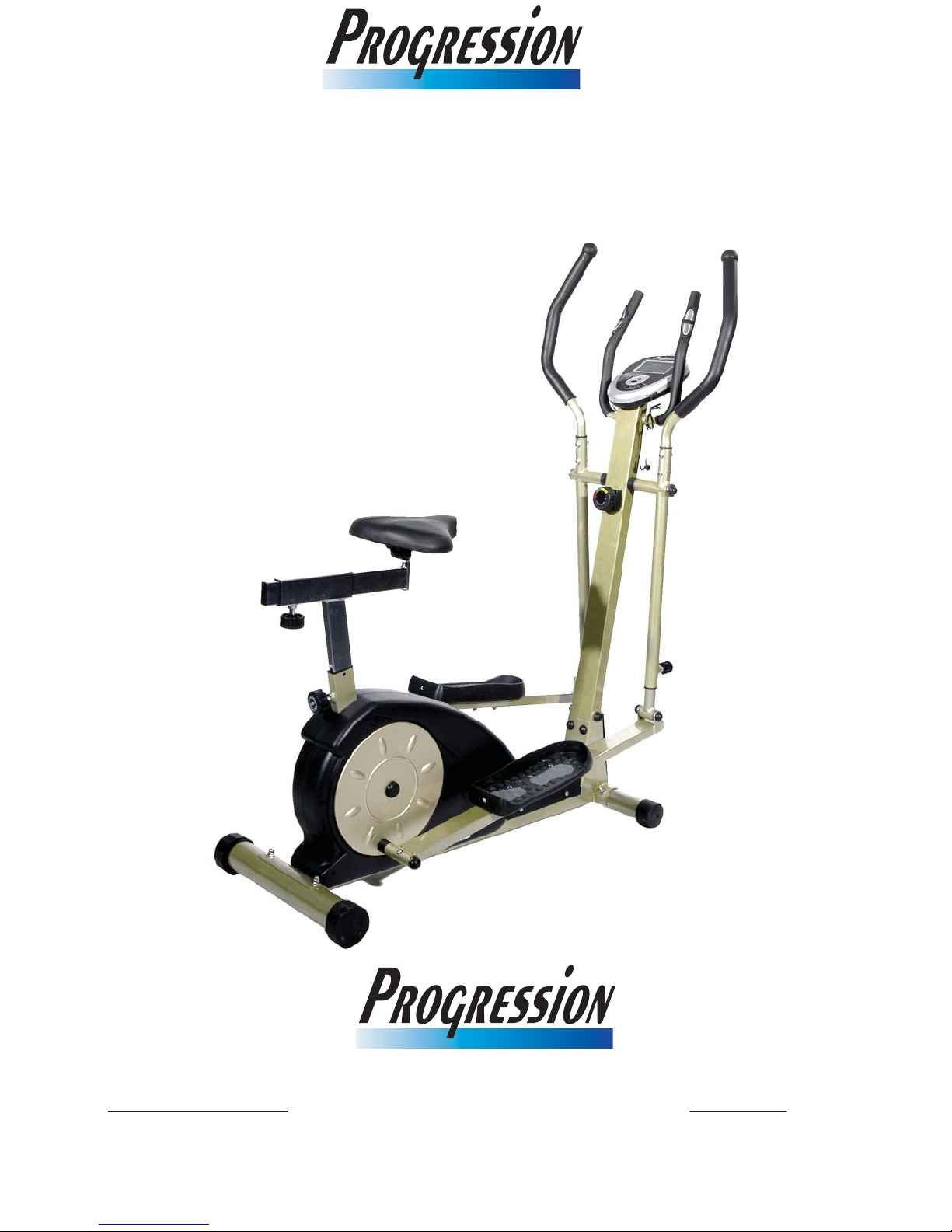
TK1202 Magnetic Bike/Elliptical
OWNER’S MANUAL
Fitness
™
Fitness
™
SASKATCHEWAN
120 Robin Crescent
Saskatoon, Saskatchewan
(306) 978-1999
Toll Free 1-866-978-1999
ALBERTA
8910 Yellowhead Trail
Edmonton, Alberta
(780) 474-2222
Toll Free 1-877-352-6263

T
hank you for your purchase! Please take a moment to familiarize yourself
with this user’s manual. Keep it with your sales receipt for future reference.
Safety Notice- READ THIS FIRST
1. THE MAXIMUM WEIGHT CAPACITY OF THE MACHINE is 265 lbs.
(120 kg). Persons whose body weight exceeds this limit should
NOT use this exercise bike/elliptical.
2. Keep children and pets away from the machine at all times. DO
NOT leave unattended children in the same room with the
machine.
3. If the user experiences dizziness, nausea, chest pain or any other
abnormal symptoms, STOP the workout at once. CONSULT A
PHYSICIAN IMMEDIATELY.
4. Position the Progression TK1202 on a large mat over a clear, level
surface. DO NOT use near water or outdoors.
5. Always wear appropriate workout clothing when exercising.
Running or aerobic shoes are also required.
6. Use the machine only for its intended use as described in this
manual. DO NOT use any other accessories not recommended by
the manufacturer.
7. DO NOT place any sharp objects around the Progression TK1202.
8. Handicapped or disabled persons should not use the machine
without the presence of a qualified health professional or
physician.
9. Always stretch before exercising.
10. NEVER operate the machine if it is not functioning properly.
Warning: Before beginning this or any exercise program, consult
your physician first. This is especially important for individuals over
the age of 35 or persons with pre-existing health problems. Read all
instructions before using. The manufacturer assumes no
responsibility for personal injury or property damages sustained by
or through the use of this product.
- 2 -
- 3 -

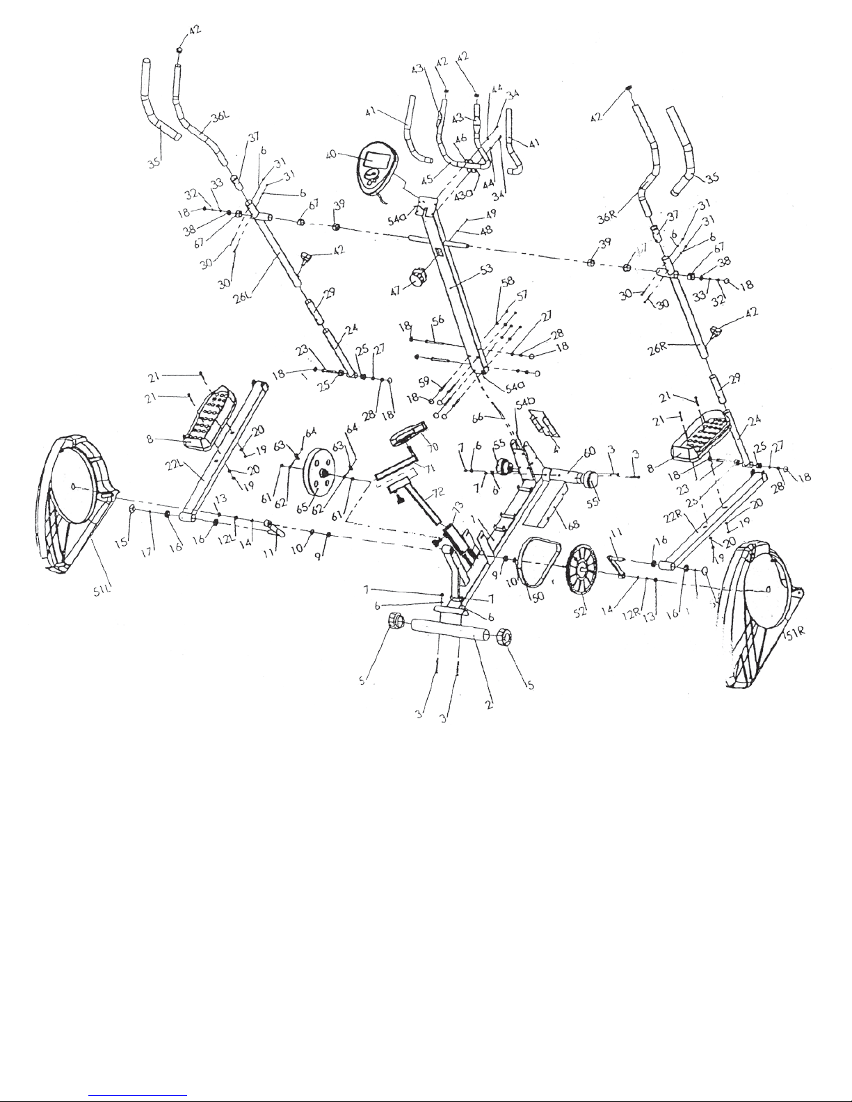
Parts List
Part
No.
Description Qty Part
No.
Description Qty
1. Main frame 1 37. Plastic sleeve 2
2. Rear stabilizer 1 38. Washer φ25.2x2xφ38 2
3. Carriage bolt M8 x 70 4 39. Bushing 2
4. Front plug 1 40. Computer 1
5. End Cap 2 41. Foam grips 2
6. Curved washer 6 42. Spring knob 4
7. Cap nut M8 4 43. Hand pulse sensor 2
8. Pedal 2 44. Washer 2
9. Bushing 2 45. Safety handle bar 1
10. C clip d16 2 46. Plug 1
11. Crank arm 2 47. Resistance regulator 1
12. Friction nut M10x1xφ19 2 48. Washer φ6x1.2x φ12 1
13. End cap for crank arm M22x1 2 49. Phillips screw M6x20 1
14. Round plastic cap 14 50. Sensor wire a & b 2
15. Round plastic cap φ 35 2 51. Plastic chain cover R & L 1
16. Bushing 2 52. Pedal crank disc 1
17. Washer d16 2 53. Handle bar post 1
18. Round plastic cap 14 54. Sensor wire a & b 2
19. Lock nut M8 2 55. End cap 2
20. Flat washer φ8x1.5xφ19 2 56. Hexagonal bolt M10x10.5 2
21. Hexagonal bolt M8x45 2 57. Nut M8 4
22. Pedal tube R&L 2 58. Washer φ6x1.2x φ12 1
23. Hexagonal bolt M8x45 2 59. Hexagonal bolt M8x55 4
24. Lower handle bar 2 60. Front stabilizer 1
25. Powder bushing φ28xφ 15x15 4 61. Hexagonal bolt 2
26. Middle handlebar tube R&L 262.Bolt 2
27. Flat washer φ10x2xφ20 4 63. U shape plug 2
28. Lock nut 4 64. Nut M6 2
29. Plastic sleeve 2 65. Flywheel 1
30. Hexagonal bolt M6x 40 4 66. Resistance regulator line 1
31. Cap nut M6 2 67. Powder bushing φ34xφ25.2x21 4
32. Hexagonal bolt M8x16 2 68. Bottom plug 1
33. Spring washer d10 2 69. Seat 1
34. Hexagonal bolt M8x25 2 70. Seat slider 1
35. Foam grips 2 71. Seat post 1
36. Upper handle bar R&L 2 72. Oblique pipe 1
Assembly Instructions
This manual is designed to help you easily assemble, adjust and use your
exercise machine. Please read this manual carefully. Read ahead before you
start: study the overview drawings to familiarize yourself with the parts
identified in the instructions.
Set all the parts in a clear area on the floor. Do not discard any packing
material until assembly is complete. Refer to the parts list for help to identify
the parts.
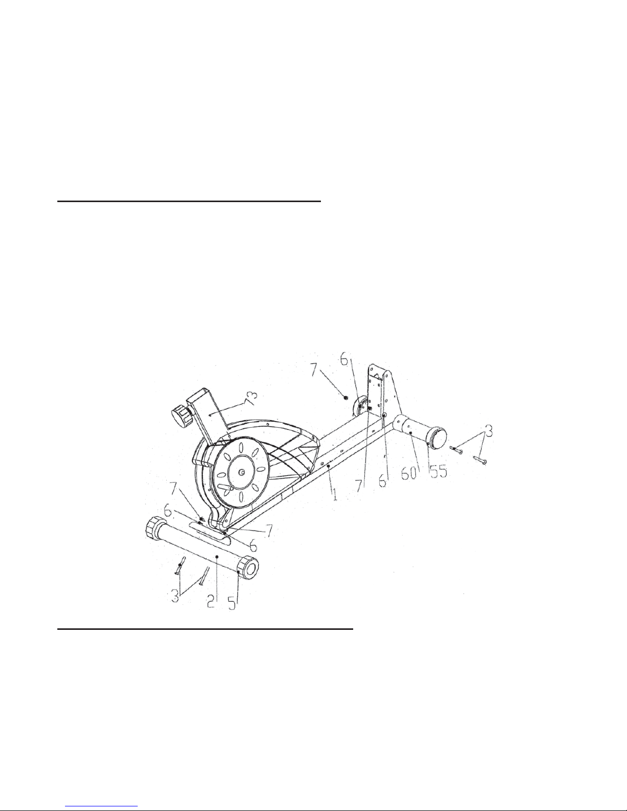
STEP 1. ATTACH THE STABALIZERS
•Attach the front stabilizer (60) with end caps (55) to the frame (1), using
two carriage bolts (3), two curved washers (6) and two cap nuts (7).
•Attach the rear stabilizer (2) with end caps (5) to the frame, using two
carriage bolts (3), two curved washers (6) and two cap nuts (7).
Note: During these two steps, please make sure the bolts are securely
tightened to avoid shaking and discomfort when cycling. Always situate the
machine on a flat, level surface free of debris.
STEP 2. ATTACH THE HANDLEBAR POST
•Connect upper sensor (54a) wire and the lower sensor wire (54b).
•Guide the handle bar post (53) into the U type bracket on the front of the
frame (1). Place two hexagonal bolts (56) into their place on the U
bracket, followed by two flat washers (27), and two M10 lock nuts (28).
Attach the handle bar post (53) by using the hexagonal bolts (59) and the
washer (58) and the nuts (57). First tighten the nuts (57). Then cover
the heads of hexagonal bolts (59) with the round plastic caps (18).
- 5 -

NOTE: Ensure the bolts are securely fastened to avoid shaking and
discomfort when exercising.
STEP 3. ATTACH PEDAL TUBE & PEDAL&SEAT
•Attach two crank arms (11) to the crank axle on the frame (1). If
necessary, use a rubber mallet to tap each crank into place. Put a toothed
washer (14) on the crank axle, securing it with a friction nut (12 R&L).
NOTE: The right nut (12R) should be threaded on clockwise. The left nut
(12L) should be threaded on counter-clockwise. Please make sure both nuts
(12R&L) are tightened securely.
•Attach the pedals (8) to the lower extremes of the pedal tubes (22R&L).
Use four washers (20) and lock nuts (19) and four hexagonal bolts (21) to
secure the pedals (8).
NOTE: Each pedal’s flat edge should point outwards.
•Put six M10 plastic caps on the heads of the nuts.
Fasten the seat (69) to the seat slider (70) into the tube with spring knob
(42) to lock firmly.
- 6 -
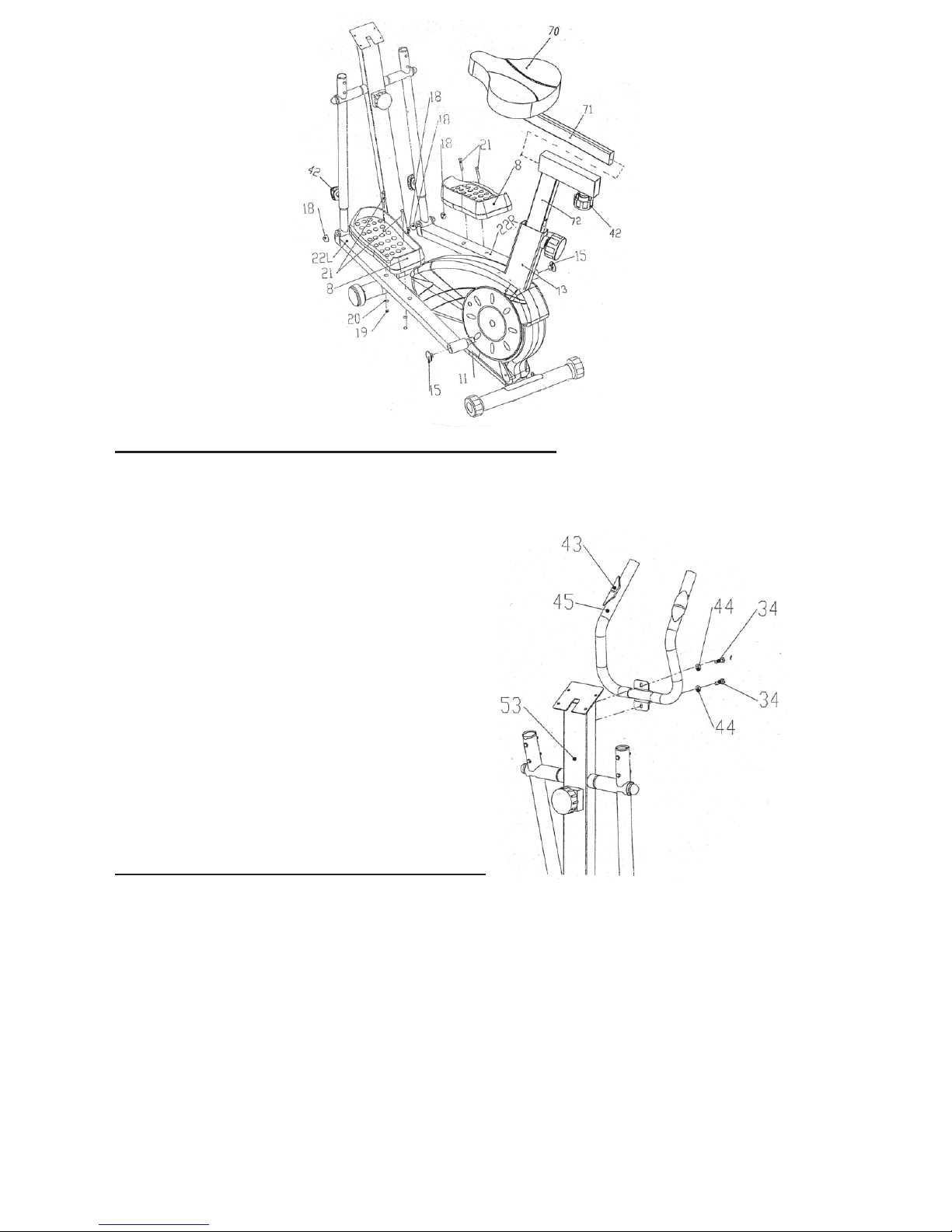
STEP 4. ATTACH THE SAFETY HANDLEBAR
•Attach safety handlebar (45) to the handlebar post (53) and secure with
two washers (44), and two hexagonal bolts (34).
STEP 5. ATTACH THE HANDLEBARS
•Insert two upper handle bars (36R&L) into the middle handle bars
(26R&L), then secure them with four curve (6) washers, four cap nuts (31)
and four hexagonal bolts (30).
•Slide foam grips (35) down to the upper handle bars (36R&L). Warm
soapy water will make it easier to slide them on.
- 7 -

STEP 6. ATTACH COMPUTER
•Hold the computer (40) in hand. Make sure the batteries are correctly
installed into the computer. First connect upper sensor wire (54a) to
the computer. Then, plug hand pulse (43a) cable into the computer.
•Tuck all extra lengths of the upper sensor wire (54a) into the handle bar
post (53). Then install the computer (40) onto the computer bracket on
the handle bar post (53) via a clip.
Note: Be careful not to pinch the cables.
- 8 -

- 9 -
both
that needs to be preset, a “set” will flash on the setting window,
Table of contents
Other Progression Fitness Elliptical Trainer manuals


Popular Elliptical Trainer manuals by other brands


AFG
AFG 5.3AE owner's manual

Horizon Fitness
Horizon Fitness ANDES 6 owner's manual

Gold's Gym
Gold's Gym Stride Trainer 380 user manual

Octane Fitness
Octane Fitness CROSS CiRCUIT PRO KIT Assembly and operation instructions

Horizon Fitness
Horizon Fitness HZ SERIES EX-22 user guide

VIRTUFIT
VIRTUFIT Elite FDR 2.5i Semi-Pro Crosstrainer user manual


