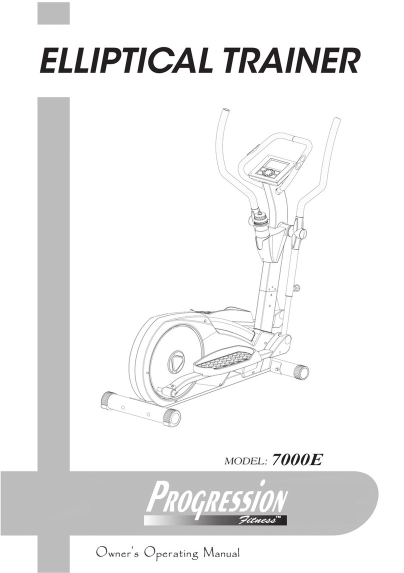
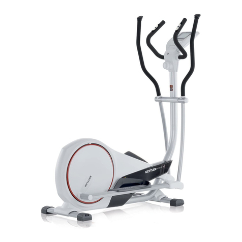
Progression Fitness 1638 Elliptical User manual


TABLE OF CONTENTS
Page Page
Safety Instructions 2 Conditioning Guidelines 11
Hardware Identification Chart 3 Warm-up and Cool-Down 12
Assembly Instructions 4 Product Parts Drawing 13
Set Up Instructions 9 Parts List 14
Operational Instructions 10 Computer Instructions 16
SAFETY INSTRUCTIONS
WARNING: To reduce the risk of serious injury, read the following Safety Instructions before using the
Progression 1638 Elliptical.
1.Read this Owner’s Manual and follow it carefully before using the Progression 1638 Elliptical.. Make sure that it is
properly assembled and tightened before use.
2.We recommend that two people be available for assembly of this product.
3. Keep children and pets away form the Progression 1638 Elliptical when it is in use.
4.It is recommended that you place this exercise equipment on an equipment mat.
5.On a solid level surface do not position the Progression 1638 Elliptical on loose rugs or uneven surfaces.
6.Adjust the LEVELING CAPS on the REAR STABILIZER so that the Progression 1638 Elliptical sits on the floor
without rocking.
7.Inspect and tighten the Progression 1638 Elliptical for worn or loose components prior to use.
8.Before exercising, securely tighten both adjustment knobs which secure the Pedal Supports.
9.Consult a physician prior to commencing an exercise program. If, at any time during exercise, you feel faint, dizzy, or
experience pain, stop and consult your physician.
10.Follow your physician’s recommendations in developing your own personal fitness program.
11.Consult your physician before using the Body Fat Program (P8) or any of the Heart Rate Control Programs
(P9 to P12). See pages 15 and 16 for a description of these programs.
12.Always choose the workout which best fits your physical strength and flexibility level. Know your limits and train
within them. Always use common sense when exercise.
13.Do not wear loose or dangling clothing while using the Progression 1638 Elliptical.
14.Never exercise in bare feet or socks; always wear correct footwear, such as running, walking, or crosstraining
shoes. Be sure that they fit well, provide foot support and feature non-skid rubber soles.
15.Be careful to maintain your balance while using, mounting, dismounting, or assembling the Progression 1638
Elliptical, loss of balance may result in a fall and serious bodily injury.
16.Keep both feet firmly and securely on the Foot Pedals while exercising.
17.The Progression 1638 Elliptical should not be used by persons weighing over 136 kgs / 300 lbs.
18.The Progression 1638 Elliptical should be used by only one person at a time.
WARNING: Before starting any exercise or conditioning program you should consult with your personal physician to see if you
require a complete physical exam. This is especially important if you are over the age of 35, have never exercised before, are
pregnant, or suffer from any illness. READ AND FOLLOW THE SAFETY PRECAUTIONS. FAILURE TO FOLLOW
THESE INSTRUCTIONS CAN RESULT IN SERIOUS BODILY INJURY.
2

HARDWARE IDENTIFICATION CHART
(94)
(108)
(104)
(105)
FRONT STABILIZER (3) REAR STABILIZER (2)
(113)
(108)
(92)
(101)
(110)
(106)
UPRIGHT (4) PEDALARM(14)
(100)
(105)
(102
)
(90)
LINKAGE(13)
LEFT HANDLEBAR (5)
RIGHT HANDLEBAR(6)
(93)
(105)
(108)
(92)
STATIONARY HANDLEBAR(7) COMPUTER(39)
(97)
(86
)
PEDAL CAP(79) MOUNTING BRACKET(61)
NOTE: Some of the hardware items listed may be attached to other parts.
3

ASSEMBLY INSTRUCTIONS
Place all parts form the box in a cleared area and position them on the floor in front of you. Remove all packing
materials from your area and place them back into the box. Do not dispose of the packing materials until assembly is
completed. Read each step carefully before beginning.
STEP 1:
Attach the FRONT STABILIZER(3), the one with wheel, onto the MAIN FRMAE(1) with
SCREWS(M8 x 90mm)(94) and M8 SPRING WASHER(108).
STEP 2
Attach the REAR STABILIZER(2) onto the MAIN FRAME(1) with SCREWS(M8 x 85mm)(104)
and NYLOCK NUTS(M8)(105).
NOTE: You can adjust the LEVELING CAPS(76) on the REAR STABILIZER(2) to keep the
Progression 1638 Elliptical stable.
4

ASSEMBLY INSTRUCTIONS
STEP 3
Connect the LOWER CONNECTION WIRE(37) to UPPER CONNECTION WIRE(38).
Insert the UPRIGHT(4) into the MAIN FRAME(1) and secure with SCREWS(M8 x 50mm)(113),
SCREWS(M8 x 25mm)(92), and M8 SPRING WASHERS(108). CAUTION: Be careful not to
damage the wires.
NOTE: The opening in the channel on the UPRIGHT(4) must be facing toward the back as shown.
5

ASSEMBLY INSTRUCTIONS
STEP 4
NOTE: There is a “L” decal on the LEFT PEDAL BRACKET(56) attached to the left PEDAL RAIL
ASSEMBLY. Attach the left PEDAL RAILASSEMBLY to the left side of the Elliptical unit. There is
a “R” decal on the RIGHT PEDAL BRACKET(57) attached to the right PEDAL RAILASSEMBLY.
Attach the right PEDAL RAILASSEMBLY to the right side of the Elliptical unit.
Attach the RIGHT PEDALARM(14) to the MAIN FRAME(1) with SCREWS(M10x85mm)(101),
M10 WASHER(110), and M10 NYLOCK NUT(106).
Connect the RIGHT PEDALARM(14) to RIGHT PIVOTING ARM(11), and secure with
SCREWS(M8x90mm)(100) and M8 NYLOCK NUT(105).
STEP 5
Connect the RIGHT LINKAGE(13) to the RIGHT LOWER HANDLEBAR POST(12) and secure
with SCREWS(M8x90mm)(100) and M8 NYLOCK NUT(105).
Attach the REAR RAIL CAP(72) to the RIGHT PEDALARM(14).
Attach the PEDAL CAPS(79) onto the RIGHT PEDAL BRACKET(57) with SCREWS
(M8 x 16mm)(97). CAUTION: The lip on the PEDAL CAPS(79) must face inside.
The sides without a lip face outside as shown.
STEP 6
Repeat the above steps on the left side. 6

ASSEMBLY INSTRUCTIONS
STEP 7
Slide the STATIONARY HANDLEBAR SLEEVE(46) onto the STATIONARY HANDLEBAR(7).
Connect the Pulse Sensor Wire (42) to the Pulse Wire (40). Insert the STATIONARY
HANDLEBAR(7) onto the UPRIGHT(4) and secure with SCREWS (M8x35mm)(93) and M8
NYLOCK NUT(105).
STEP 8
Connect the RIGHT PULSE WIRE(38) and the LEFT PULSE WIRE(40) to the COMPUTER(39).
Attach the COMPUTER(39) onto the UPRIGHT(4) by inserting the BRACKET in the
COMPUTER(39) into the UPRIGHT(4) and secure with SCREWS(M8 x 25mm)(92) and
M8 SPRING WASHERS(108).
CAUTION: Be careful not to damage the wires.
7

ASSEMBLY INSTRUCTIONS
11
62
STEP 9
There is a “L” decal on the LEFT HANDLEBAR(8), and a “R” decal on the RIGHT HANDLEBAR
(9). Slide the HANDLEBAR SLEEVE(48) onto the RIGHT HANDLEBAR(9). Insert the RIGHT
HANDLEBAR(9) onto the RIGHT PIVOTING ARM(11) and secure with SCREWS
(M6 x 35mm)(90) and NYLOCK NUTS(M6)(102). CAUTION: Be careful not to damage the wires.
Slide the HANDLEBAR SLEEVE(48) down to cover the bolts on the RIGHT HANDLEBAR(9).
Repeat on the left side.
STEP 10
Attach the MOUNTING BRACKET(61) onto the UPRIGHT(4) with SCREWS(M5 x 12mm)(86).
Place the WATER BOTTLE(62) in the MOUNTING BRACKET(61).
STEP 11
Connect the ADAPTER(77) to the connector located on the base of the MAIN FRAME(1), refer
to the inset drawing. Plug the ADAPTER(77) into an electrical outlet.
8

SET UP INSTRUCTIONS
Place the Progression 1638 Elliptical in the area where it will be used. It is recommended that the
Progression 1638 Elliptical be placed on an equipment mat.
LEVELING: Adjust the LEVELING CAPS(76) on the REAR STABILIZER(2) so that the
Progression 1638 Elliptical sets on the floor without rocking. Remove and reposition the
LEVELING CAPS(76) on the REAR STABILIZER(2) to level the Progression 1638 Elliptical.
MOVING: The Progression 1638 Elliptical has a pair of MOVING WHEELS(75) built into the
FRONT STABILIZER(3) at the front. Grasp the center section of the HANDLEBARS(8,9) and tip
the Progression 1638 Elliptical forward to move.
GRASPHERETO MOVE
GRASP HERETO MOVE
39
9
8
3
76
2
FUNCTION INSPECTION:
Visually inspect the Progression 1638 Elliptical to verify that assembly is as shown in the above
illustration. Check the function of the Progression 1638 Elliptical. Stand on the foot pedals and
place your hands at a comfortable position on the handlebars. Slowly move your highest foot
forward and follow the natural path of the machine. Turn the crank slowly through one complete
revolution to verify that the drive train functions properly. Use the “+/-“ buttons on the
COMPUTER(39) to select a program and verify that the Magnetic System provides different
tensions. Refer to the COMPUTER INSTRUCTIONS on pages 11 to 14.
CAUTION: Locate and read the Warning Label on the Progression 1638 Elliptical. Make sure that
all users read the Warning Label.
9

OPERATIONAL INSTRUCTIONS
STRIDE LENGTH LEVEL ADJUSTMENT
To exercise in different stride length (3 levels) by adjusting the LOWER HANDLEBAR POST(12)
as following.
Refer to the above illustration.
1. Loosen the SPRING KNOB(66) by turning counter-clockwise then pulling out and holding up
the SPRING KNOB(66)
2. Adjust the LOWER HANDLEBAR POST(12) up or down to attach the ideal level.
3. Turn the SPRING KNOB(66) clockwise to tighten up.
Load Level Adjustment
The load level of Progression 1638 Elliptical can be changed at any time during your workout.
Adjusting the load level will allow you to increase or decrease your intensity level. Press the “+”
button to increase the load level. Press the “-” button to decrease the load level.
10
520mm (21”)
480mm (20”)
445mm (19”)

CONDITIONING GUIDELINES
How you begin your exercise program depends on your physical condition. If you have been
inactive for several years, or are severely overweight, you must slowly and increase your time on
the Elliptical gradually: a few minutes per workout.
Initially, you may be able to exercise only for a few minutes in your target zone, however, your
aerobic fitness will improve over the next six to eight weeks. Don’t be discouraged if it takes longer.
It’s important to work at your own pace. Ultimately, you’ll be able to exercise continuously for 30
minutes. The better your aerobic fitness, the harder you will have to work to stay in your target
zone. Please remember these essentials:
˙Have your doctor review your training and diet programs to advise you of a workout routine you
should adopt.
˙Begin your training program slowly with realistic goals that have been set by you and your
doctor.
˙Monitor your pulse frequently. Establish your target heart rate base on your age and condition.
EXERCISE INTENSITY
To maximize the benefits of exercising, it is important to exercise with the proper intensity. The
proper intensity level can be found by using your heart rate as a guide. For effective aerobic
exercise, your heart rate should be maintained at a level between 70% and 85% of your maximum
heart rate as you exercise. This is known as your target zone. You can find your target zone in the
table below. Target zones are listed for both unconditioned and conditioned persons according to
age.
During the first few months of your exercise program, keep
your heart rate near the low end of your target zone as you
exercise. After a few months, your heart rate can be
increased gradually until it is near the middle of your target
zone as you exercise.
To measure your heart rate manually,
stop exercising but continue moving
your legs or walking around and
place two fingers on your wrist. Take
a six-second heartbeat count and
multiply the results by 10 to find your
heart rate. For example, if your six-second heartbeat count is
14, your heart rate is 140 beats per minute. (A six-second
count is used because your heart rate will drop rapidly when
you stop exercising.) Adjust the intensity of your exercise until
your heart rate is at the proper level.
11

WARM-UP and COOL-DOWN
Warm-up The purpose of warming up is to prepare your body for exercise and to minimize injuries. Warm
up for two to five minutes before strength-training or aerobic exercising. Use the elliptical at a slower less
intensive pace. Perform activities that raise your heart rate and warm the working muscles.Activities may
include brisk walking, jogging, jumping jacks, jump rope, and running in place.
Stretching Stretching while your muscles are warm after a proper warm-up and again after your strength or
aerobic training session is very important. Muscles stretch more easily at these times because of their
elevated temperature, which greatly reduces the risk of injury. Stretches should be held for 15 to 30 seconds.
Do not bounce.
Suggested Stretching Exercises
Lower Body Stretch
Place feet shoulder-width
apart and lean forward. Keep
this position for 30 seconds
using the body as a natural
weight to stretch the backs of
the legs.
DO NOT BOUNCE!
When the pull on the back of
the legs lessen, try a lower
position gradually.
h
Floor Stretch
While sitting on the floor, open
the legs as wide as possible.
Stretch the upper body toward
the knee on the right leg by
using your arms to pull your
chest to your thighs. Hold this
stretch 10 to 30 seconds.
DO NOT BOUNCE!
Do this stretch 10 times.
Repeat the stretch with the left
leg.
Bent Torso Pulls
While sitting on the floor,
have legs apart one leg
straight and one knee bent.
Pull the chest down to touch
the thigh on the leg that is
bent and twist at the waist.
Hold this position at least 10
seconds. Repeat 10 times on
each side.
Bent Over Leg Stretch
Stand with feet shoulder-width
apart and lean forward as
illustrated. Using the arms,
gently pull the upper body
towards the right leg. Let the
head hand down. DO NOT
BOUNCE! Hold the position a
minimum of 10 seconds.
Repeat pulling the upper body
to the left leg. Do this stretch
several times slowly.
Remember always to check with your physician before starting any exercise program.
Cool-Down The purpose of cooling down is to return the body to its normal, or near normal, resting state at
the end of each exercise session. A proper cool-down lowers your heart rate and allows blood to return to
the heart. Your cool-down should include the stretches listed above and should be completed after each
strength-training session.
12

FR
O
NT
13

PARTS LIST
NO. PART NAME QTY NO. PART NAME QTY
1 Main Frame 1 46 Stationary Handlebar Sleeve 1
2 Rear Stabilizer 1 47 Foam Grip 2
3 Front Stabilizer 1 48 Handlebar Sleeve 2
4 Upright 1 49 Hollow Cap 2
5 Left AL Upright 1 50 Pivot Bar Bushing 4
6 Right AL Upright 1 51 Large Washer M8x60mmx3t 2
7 Stationary Handlebar 1 52 Securing Knob 2
8 Left Handlebar 1 53 U Bracket 2
9 Right Handlebar 1 54 Spacer 12 x8.2x74mm 4
10 Left Pivoting Arm 1 55 Pedal Rail 2
11 Right Pivoting Arm 1 56 Pedal Bracket (L) 1
12 Lower Handlebar Post 2 57 Pedal Bracket (R) 1
13 Linkage 2 58 PU Wheel 8
14 Pedal Arm 2 59 Spacer 8x7.5mm 8
15 Pedal Arm Connector 2 60 Spacer 8.2x25mm 4
16 Crank 2 61 Mounting Bracket 1
17 Crank Cover 2 62 Water Bottle 1
18 Left Cover 1 63 Upper Pulse Sensor Plate 2
19 Right Cover 1 64 Lower Pulse Sensor Housing 2
20 Left Upright Cover 1 65 Round Plug 32mm 2
21 Right Upright Cover 1 66 Spring Knob 2
22 Shaft 1 67 Handlebar Post Sleeve 2
23 Bearing (6004Z) 2 68 Bushing 38mm 8
24 Washer M20 2 69 Front Rail Cap (L) 2
25 C Ring 20mm 2 70 Front Rail Cap (R) 2
26 Pulley 1 71 Sleeve 4
27 V-Ribbed Belt 1 72 Rear Rail Cap 2
29 Eddy Current Breaker(EMS) 1 73 Oval Cap 2
30 EMS Connection Wire 1 74 Round End cap 76mm 2
31 Control Board 1 75 Moving Wheel 2
32 Power Connection Wire 1 76 Leveling Cap 76mm 2
34 Magnet 1 77 Adapter 1
35 Sensor Wire 1 78 Spacer 8.2x16mm 2
36 Plug Nut 1 79 Pedal Cap (L,R) 2
37 Lower Connection Wire 1 80 Screw, M3x10mm 4
38 Upper Connection Wire 1 81 Screw, M4x20mm 12
39 Computer 1 82 Screw, M5x12mm 1
40 Pulse Wire 1 83 Screw, M5x20mm 14
42 Pulse Sensor Wire 2 84 Screw, M4x16mm 4
45 Stationary Handlebar Cover 2 85 Screw, M4x20mm 4
14

86 Screw, M5x12mm 2
87 Screw, M8x30mm 2
88 Screw, M5x20mm 4
89 Screw, M6x10mm 8
90 Screw, M6x35mm 4
92 Screw, M8x25mm 4
93 Screw, M8x35mm 2
94 Screw, M8x90mm 2
95 Screw, M8x16mm 4
96 Screw, M8x25mm 2
97 Screw, M8x16mm 8
98 Screw, M8x25mm 4
99 Screw, M8x30mm 4
100 Screw, M8x90mm 4
101 Screw, M10x85mm 2
102 Nylock Nut, M6 4
103 Nut, M8x6mm 12
104 Screw, M8x85mm 2
105 Nylock Nut, M8 12
106 Nylock Nut, M10 2
107 Flange Nut, M10 3
108 M8 Spring Washer 12
109 Screw, M5x15mm 2
110 M10 Washer 4
111 M17 Washer 6
112 E Ring (17mm) 2
113 Screw, M8x50mm 2
15

INSTRUCTION MANUAL
zKey Functions
zAbout Displays
zOperating Ranges
zThings You Should Know Before Exercising
zOperation Instructions
Key Functions
START/STOP
1. Use this key to active or shutdown the console.
2. Press and hold over 2 seconds, to reset all functions back to default values (except WATT and Target
H.R)
3. During sleep mode, press this key to wake up to normal stage.
4. During user program setting mode, press this key to save data.
5. During body fat program, press this key to begin measuring.
ENTER MODE
1. During stop mode, use this key to enter setting mode for each program.
2. For program 1 ~ 10, press ENTER key to navigate through settings as follow:
Program ÆTime / Distance ÆWAT T
3. For program 11 and 12, press ENTER key to navigate through settings as follow:
Program ÆTime / Distance ÆAge
16

4. For program 13 and 14 press ENTER key to navigate through settings as follow:
Program ÆTime / Distance ÆAge ÆWATT
5. For program 15 press ENTER key to navigate through settings as follow:
Program ÆGENDER ÆHEIGHT ÆWEIGHT ÆAge
UP Key
1. During stop mode, press this key to navigate through programs as follow:
Program 1 ÆProgram 2 Æ… ÆProgram 14 ÆProgram 15 Ærepeat
2. During start mode, press this key to increase WATT level by 10. Press and hold for 2 seconds to
increase Watt value rapidly (8x per second).
3. In time setting mode, press this key to increase time value. Distance value will default to zero.
4. In distance setting mode, press this key to increase distance value. Time value will default to zero.
5. In WATT setting mode, press this key to increase WATT value by 10, up to 300 (400) Watt max.
DOWN Key
1. During stop mode, press this key to navigate through programs as follow:
Program 1 ÆProgram 15 Æ… ÆProgram 3 ÆProgram 2 Ærepeat
2. During start mode, press this key to decrease WATT level by 10. Press and hold for 2 seconds to
decrease Watt value rapidly (8x per second).
3. In time setting mode, press this key to decrease time value. Distance value will default to zero.
4. In distance setting mode, press this key to decrease distance value. Time value will default to zero.
5. In WATT setting mode, press this key to decrease WATT value by 10, down to 10% of Watt
maximum value.
PULSE RECOVERY
Press this key to enter pulse recovery detecting mode.
RESET
In stop mode, press and hold this key over 2 seconds to reset all displaying values.
About Displays
A. START: Indicates the program selected has started.
B. STOP: Indicates the program selected has stopped. And, users are free to change the programs and
the value of functions applied.
C. PROGRAM : Indicates the programs selected from PROGRAM 1 to PROGRAM 15
17

D. GENDER: Indicates the gender (Male or Female) selected.
E. TIME/HEIGHT Display: Indicates only 1 value of TIME, HEIGHT, displayed depending on the
programs.
F. RPM/SPEED/WEIGHT Display: Indicates only 1 value of RPM, SPEED, or WEIGHT displayed
depending on the programs.
G. DISTANCE/FAT% Display: Indicates only 1 value of DISTANCE or FAT% displayed depending on
the programs.
H. KJOULE /CAL /BMR Display: Indicates only one value of KJOULE or CAL, or BMR displayed
depending on the programs.
I. WATT/TARGET H.R./BMI/AGE Display: Indicates only one value of WATT, TARGET HEART
RATE, BMI, or AGE displayed depending on the programs.
18

J. HEART RATE/BODY TYPE Display: Indicates only one value of HEART RATE or BODY TYPE
displayed depending on the programs.
K. LOADING Profiles: There are 10 columns of loading bars, and 10 bars in each column. Each
column represents 3 minutes workout (without the change of TIME value ), and each bar represents
2 watt levels of loading.
Operating Ranges
Values Range (Count up) Count down Preset Increment (Decrement)
PROGRAM 1 ~ 15 15 ~ 1 1 1
WATT 30 ~ 300 300 ~ 30 N/A 10
GENDER Male, Female N/A Male N/A
TIME 0:00 ~ 99:59 99:00 ~ 5:00 0:00 1:00
HEIGHT (cm) 110.0 ~ 199.5 199.5 ~ 110.0 175.0 0.5
WEIGHT (kg) 10.0 ~ 199.8 199.8 ~ 10.0 70.0 0.2
DISTANCE 0.0 ~ 999.0 999.0 ~ 1.0 0.0 1.0
AGE 10 ~ 99 99 ~ 10 30 1
Things You Should Know Before Exercising
A. The values calculated or measured by the computer are for exercise purpose only, not for medical
purpose.
B. The Variables May Need To Change In The Programs:
Programs Variables
P1 ~ P10 TIME, DISTANCE
P15 GENDER, HEIGHT, WEIGHT, AGE
P11 ~ P12 TIME, DISTANCE, AGE
P13 ~ P14 TIME, DISTANCE, AGE, 10 Intervals
Please note that only 1 value of TIME or DISTANCE can be adjusted. Both adjustments do not
exist at the same time. For example, the value of DISTANCE is “0.0” while the value of TIME is
adjusted to be any number except “00:00”.
19

C. Programs Selection:
There are 15programs include 1 Manual Program, 9 Preset Programs, 1 Body Fat Program, 2 Heart
Rate Control Programs, and 2 User Setting Programs.
D. Program Graph:
Each graph shown is the profile of the loading in each interval (column). With the value of TIME
counting up, each interval is 3 minutes that all the columns make up 30 minutes. With the value of
TIME counting down, each interval is the value of setup TIME divided by 10. For example, if the
time value is setup to 40 minutes, each interval will be 40 minutes divided by 10 intervals (40/10=4).
Then, each interval will be 4 minutes. The following graphs are all the profiles in the monitor.
E. Body Types:
There are 9 body types divided according to the FAT% calculated. Type 1 is from 5% to 9%.
Type 2 is from 10% to 14%. Type 3 is from 15% to 19%. Type 4 is from 20% to 24%. Type 5 is
from 25% to 29%. Type 6 is from 30% to 34%. Type 7 is from 35% to 39%. Type 8 is from
40% to 44%. Type 9 is from 45% to 50%.
F. BMR: Basal Metabolism Ratio
G. BMI: Body Mass Index
20
Table of contents
Other Progression Fitness Fitness Equipment manuals
Progression Fitness
Progression Fitness X-plode PFX – 220 User manual
Progression Fitness
Progression Fitness X-plode PFX260 User manual
Progression Fitness
Progression Fitness 75112 User manual
Progression Fitness
Progression Fitness 500E Operation manual
Progression Fitness
Progression Fitness PV500 User manual
Progression Fitness
Progression Fitness PFX260 User manual
Progression Fitness
Progression Fitness X-plode PFX-1000 User manual
Progression Fitness
Progression Fitness B1100 Operation manual
Progression Fitness
Progression Fitness X-plode 200 Sled Installation and operating instructions
Progression Fitness
Progression Fitness X-plode BK-3000F User manual
