Projecta SURE BRAKE User manual
TRAILER BREAKAWAY KIT
P/No. TBS700
SURE BRAKE 12V EMERGENCY

2
WARNING
Before using the product, read and follow the instructions carefully
• Test the internal battery status before towing the trailer
• Ensure the Sure Brake is mounted under cover, in an area protected from all
weather conditions
• Do not submerge the product in water or expose to rain
• Batteries might release explosive gases during normal operation and charging so ensure
the Sure Brake is mounted outside of internal cabin area
• Mount the unit in well ventilated and easy to access location
• Ensure the Test button is not accidentally activated by any objects
• Read the and follow the instruction on the internal label before replacing the
internal battery
• Check the Sure Brake breakaway system regularly, especially after periods of non-use
• Disconnect the trailer connector from the tow vehicle prior to testing the
breakaway system
• Make sure the (+) and (-) leads of the external charger are connected to the (+) and (-)
external charging terminals respectively
IMPORTANT
1. Prior to each use check the systems battery operating voltage.
Warning: In order to avoid severe damage to the tow vehicle’s electric brake
controller, disconnect the trailer connector from the tow vehicle prior to testing
the breakaway system.
2. Check the Sure Brake breakaway system from time to time to ensure proper
secure connections.
3. Check that the Breakaway Switch cables aren’t damaged from dragging on the
ground and that they move freely.
4. Brake light fuse is 10A. Battery fuse is 30A.
SURE BRAKE TRAILER BREAKAWAY KIT
The Sure Brake Breakaway Kit is designed to activate a trailers electric brakes if it should
disconnect while towing which will bring the trailer to a safe stop. Trailer Breakaway Kits
are required when towing trailers at 2000kg gross trailer mass (GTM) or greater.
*Your trailer must be equipped with electric brakes in order to use this kit.
FEATURES
• Durable battery case
• Internal charging via tow vehicle alternator or house battery
• External charging via terminal posts
• External charging function is compatible with most of the chargers in the market
• Fused battery connection

3
• Output for battery monitoring
• Potted circuitry with over-voltage, overcurrent and short circuit protection
• Test button and status LEDs for battery condition
• Breakaway switch with coiled cable and carabiner clip
• Step-up convertor added to provide better charging of internal battery with smart
alternator vehicles
KIT INCLUDES:
(1) Battery Case with Charging/Test Circuit
(1) Breakaway Switch with coiled cable and carabiner clip
(4) Case Mounting Screws
L.E.D STATUS INDICATORS
‘Charging’ LED: Illuminates Green when the internal battery is being charged by the
tow vehicle or house battery (auxiliary battery at the caravan/trailer).
‘Good’ LED: Illuminates Green when the internal battery has enough charge.
‘Low’ LED: Illuminates Red when the internal battery needs charging before use.
NOTE:
The LED will not turn on if external battery charger is connected to the DC terminals.
Please check the battery charger display for internal battery charging status.
INTERNAL BATTERY TEST
Push the ‘Test’ button on the front of the unit to check the internal battery condition.
The trailer brakes and brake lights will activate when the ‘Test’ button is pressed, this
operational load is applied each time the ‘Test’ button is pushed. If the battery voltage
is above 11.5V, a ‘green’ LED is illuminated. If the battery voltage drops under 11.5V, a
‘red’ LED is illuminated. If the battery is under 6V neither LED indicator will be illuminate.
‘Good’ LED – Illuminates Green when internal battery has enough charge.
‘Low’ LED – Illuminates Red when the internal battery needs charging before use.
No LED turns On – The internal battery is flat or heavily discharged. Try to charge the
battery fully. Repeat the battery test. If LOW LED turns Red or no LED turns on, replace
the internal battery.
NOTE:
1. Prior to replacing the internal battery, disconnect the trailer connector from the
tow vehicle.
2. Check the Sure Break breakaway system periodically to ensure proper secure
electrical connections.
3. Check that the breakaway switch cable isn’t damaged from dragging on the ground
and is free from obstruction.
4. Internal battery fuse is rated at 30A. Brake light fuse is rated at 10A.
4
BATTERY CHARGING
If the system measures voltage less than 13.5V, the charging circuit will provide
maximum charging current to a 12V 7Ah Battery until the battery is fully charged to
13.5V. During the operation the system provides a ‘Trickle Charge’ to maintain battery
voltage. An external charger can be used.
When battery voltage is under 6V, the internal circuit will not activate when the ‘Test’
button is pressed and the whole test circuit will have no power and will not activate
either the green or red LED. This will indicate a flat battery.
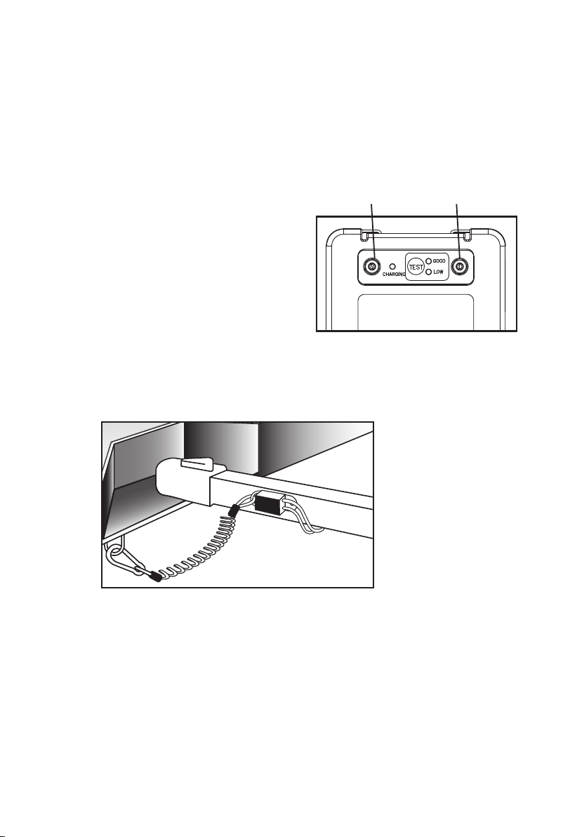
EXTERNAL CHARGING
The Sure Brake Breakaway Kit has the
option to charge the battery using an
external battery charger. Just connect
the positive clamp/cable of the external
charger to the red post and the negative
clamp/cable of the external charger to
the black post.
MOUNTING
1. Breakaway Switch: Position the Breakaway Switch on the drawbar of the trailer
such that it allows the cable to reach the tow vehicle’s hitch chain safety eyelets.
It must be mounted so the breakaway/plunger lanyard is facing the tow vehicle,
per the diagram below. This is critical for proper engagement of the switch.
Drill a 7mm hole in the trailer drawer bar frame to mount the Breakaway Switch
once you’ve located the mounting location. Use an M6 bolt and lock nut (both not
provided) to mount the Breakaway Switch to the trailer. Note: Use caution
when drilling the hole that there are no wires or other objects behind the
mounting surface. Note: Take care not to over-tighten the bolt because the
Breakaway Switch needs to pivot.
2. Battery Case: Find a suitable location on the trailer frame to mount the Breakaway
battery case. It should be mounted under cover or in an area protected from all
weather conditions.
Red Post Black Post
5
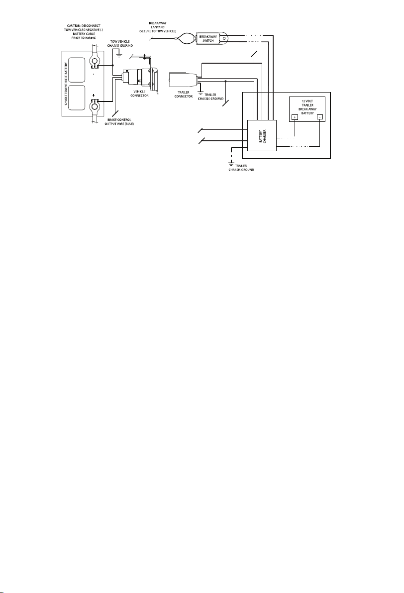
Wiring Details:
Orange (2 wires) – to Breakaway Switch (no polarity on the wires)
Red – to trailer brake lights (+ terminal)
Blue – to trailer electric brakes (+ terminal)
Ground Ring Terminal – to the chassis of the trailer
Black with White Stripe – to motor home/caravan 12V house battery (+ terminal)
if available
Black – to 12V supply from the trailer connector
Purple – to battery monitor at the vehicle (+ terminal)
WIRING INSTRUCTIONS
1. Disconnect the trailer connector from the vehicle and any internal battery the
caravan/ trailer has before wiring.
2. Do not connect internal Breakaway battery during wiring of the kit.
3. Connect the orange wires of the kit to the Breakaway Switch. There is no polarity
on the wires.
4. Splice the red wire of the kit to the trailer brake lights.
5. Splice the blue wire of the kit to the trailer electric brakes.
6. Connect the purple wire of the kit to the battery monitor.
7. Splice the black wire with white stripe of the kit to the caravan 12V system if
available (not necessary if not available).
8. Splice the black wire of the kit to the 12V supply from the trailer connector.
9. Connect the ground ring terminal to the chassis of the trailer.
10. Connect the Sure Brake Breakaway Kit battery by attaching the red wire inside the kit
to the Positive (+) terminal of the battery and the black wire to the negative (-)
terminal of the battery.
11. Test unit by pulling firmly on coiled cable of breakaway switch. The battery will
activate the trailer brakes and brake lights. (Note: Do not use this kit as a parking
brake.) The battery should be charged and tested prior to each trailer outing.
Caution: Do not attach the Breakaway Switch cable to mounting hooks,
trailer safety chains or the trailer hitch ball.
Caution: Disconnect the trailer connector from the tow vehicle and any
internal house battery before replacing Breakaway Kit battery.
12V+ (RED)12V+ (RED)
12V- (BLACK)12V- (BLACK)
BREAKAWAY
SWITCH
(ORANGE)
BREAKAWAY
SWITCH
(ORANGE)
BREAKAWAY KIT AND
BATTERY CHARGER
TRAILER BRAKES
(BLUE)
TRAILER BRAKES
(BLUE)
12V+ INPUT (BLACK)
12V+ INPUT (BLACK)
GROUND
(WHITE)
GROUND
(WHITE)
BRAKE LIGHTS
(RED)
BRAKE LIGHTS
(RED)
BATTERY MONITOR
(PURPLE)
BATTERY MONITOR
(PURPLE)
CARAVAN
BATTERY INPUT
(BLACK W/ WHITE STRIPE
OPTIONAL)

6
TROUBLE SHOOTING
Q: When an external charger is connected the charging LED on the front panel
does not turn on?
A: The charging LED only turns on when the internal battery is charged by the towing
vehicle or the house battery.
Q: When the test button is pressed the brake lights do not activate/illuminate
yet the battery status LED is green.
A: Check the brake light fuse and continuity of the cable connection. Replace fuse and
tighten the connection if required.
Q: When the test button is pressed the brakes do not lock yet the battery status
LED is green.
A: Measure the voltage at the blue cable. There should be more than 11.5V applied to
the blue wire if the battery status LED is green. If no voltage or voltage is below
11.5V, check the continuity of the cable connection. Tighten the connection if
required. If the connection and measured voltage is fine, bring the trailer to repair
shop to check the electric brakes as soon as possible.
Q: The pin was pulled from the ‘Breakaway Switch’ but the brakes did not
engage/lock.
A: Check if the pin was broken. If yes, replace the breakaway switch. Check if the
orange wires are well connected to the black wires of the breakaway switch.
Check if the orange wires are short-circuited when the pin is pulled. If not, replace
breakaway switch. If yes, measure the voltage at the blue cable. There should be
more than 11.5V applied to the blue wire if the battery status LED is green. If no
voltage or the voltage is below 11.5V, check the continuity of the cable connection.
Tighten the connection if required. If the connection and measured voltage is fine,
bring the trailer to repair shop to check the electric brakes as soon as possible.
Q: When the test button is pressed no LED illuminates.
A: Check if the internal battery terminals are connected well with female blade
terminals. If yes, replace the battery as soon as possible.
Q: When the test button is pressed the battery status LED momentarily turns
green and red.
A: The internal battery is below its full charge level. Charge the battery as soon as
possible before starting to use the trailer. If battery does not hold charge, replace
with a new battery
Q: When the tow vehicle is running and the trailer plug is engaged the charging
LED is not turned on.
A: Check if the internal battery terminals are connected well with female
blade terminals.

7
Q: When the black and white stripe wire is connected to house battery which is
being charged, the charging LED is not turned on.
A: Check if the house battery voltage is below the internal battery voltage. If yes, the
charging LED will be turned on once both battery voltages are equal. If not, check
if the internal battery terminals are connected well with female blade terminals.
Q: When using an external charger to charge the Sure Brakes internal battery,
what current setting should I use?
A: The charging current should not be set more than 2A (otherwise, the internal
resettable fuse will activate and limit the current).

Distributed by
AUSTRALIA
Brown & Watson International Pty Ltd
Knoxfield, Victoria 3180
Telephone (03) 9730 6000
Facsimile (03) 9730 6050
National Toll Free 1800 113 443
NEW ZEALAND
Narva New Zealand Ltd
22–24 Olive Road
PO Box 12556 Penrose
Auckland, New Zealand
Telephone (09) 525 4575
Facsimile (09) 579 1192 IS413
Issue 1 21.11.19
WARRANTY STATEMENT
Brown & Watson International Pty. Ltd. (“BWI”) of 1500 Ferntree Gully Road, Knoxfield,
Vic., telephone (03) 9730 6000, fax (03) 9730 6050, warrants that all products described
in its current catalogue will under normal use and service be free of failures in material
and workmanship for a period of one (1) year from the date of the original purchase by
the customer as marked on the invoice (see elsewhere for specific warranty period). This
warranty does not cover ordinary wear and tear, abuse, alteration of products or damage
caused by the purchaser.
To make a warranty claim the consumer must deliver the product at their cost to the
original place of purchase or to any other place which may be nominated by either BWI or
the retailer from where the product was bought in order that a warranty assessment may
be performed. The consumer must also deliver the original invoice evidencing the date and
place of purchase together with an explanation in writing as to the nature of the claim.
In the event that the claim is determined to be for a minor failure of the product then
BWI reserves the right to repair or replace it at its discretion. In the event that a major
failure is determined the consumer will be entitled to a replacement or a refund as well as
compensation for any other reasonably foreseeable loss or damage.
This warranty is in addition to any other rights or remedies that the consumer may have
under State or Federal legislation.
IMPORTANT NOTE
Our goods come with guarantees that cannot be excluded under the Australian Consumer
Law. You are entitled to a replacement or refund for a major failure and compensation for
any other reasonably foreseeable loss or damage. You are also entitled to have the goods
repaired or replaced if the goods fail to be of acceptable quality and the failure does not
amount to a major failure.
This manual suits for next models
1
Table of contents
Popular Safety Equipment manuals by other brands

Lanex
Lanex PB-20 instruction manual

SKYLOTEC
SKYLOTEC ANCHOR ROPES Instructions for use

Besto
Besto Buoyancy Aid 50N Instructions for use

TEUFELBERGER
TEUFELBERGER NODUS Manufacturer's information and instructions for use

Troy Lee Designs
Troy Lee Designs Tbone Product owners manual

Innova
Innova Xtirpa Instruction and safety manual

bolle SAFETY
bolle SAFETY B810 quick start guide

SHENZHEN FANHAI SANJIANG ELECTRONICS
SHENZHEN FANHAI SANJIANG ELECTRONICS A9060T instruction manual

Hiltron security
Hiltron security POWER8E Installation and use manual

Salewa
Salewa MTN SPIKE user manual

Hatco
Hatco B-950P installation guide

Sitec
Sitec TX MATIC operating manual


