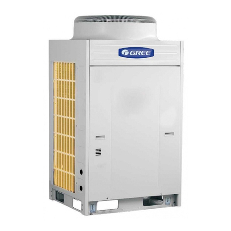
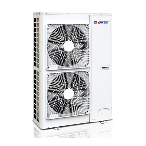
Gree GMV-S120WL/A-S User manual

GMV5HOMEDCINVERTERMULTIVRF UNITS
SERVICEMANUAL
T1/R410A/50-60Hz
(GC201509 -І )

1
CONTENTS
CHAPTER 1: PRODUCT INTRODUCTION ........................................................................................... 1
1. PRODUCT LIST................................................................................................................................... 1
1.1 Outdoor unit............................................................................................................................... 1
1.2 Hot water generator................................................................................................................... 1
1.3 Water tank.................................................................................................................................. 2
2. BASIC PARAMETER OF UNIT................................................................................................................ 2
2.1 Performance parameter of outdoor unit..................................................................................... 2
2.2 Performance parameter of hot water generator ........................................................................ 3
2.3 Performance parameter of water tank....................................................................................... 4
3. PRODUCT FUNCTIONS ........................................................................................................................ 5
3.1 Outline of Features .................................................................................................................... 5
3.2 Description of Features.............................................................................................................. 5
4. BASIC OPERATIONAL PRINCIPLE.......................................................................................................... 6
4.1 Flow Diagram of System............................................................................................................ 6
4.2 Instruction of flow....................................................................................................................... 6
5. NAMING RULES.................................................................................................................................. 7
5.1 Naming rules of outdoor unit...................................................................................................... 7
5.2 Naming rules of indoor unit........................................................................................................ 7
5.3 Naming rules of hot water generator ......................................................................................... 8
5.4 Naming rules of water tank........................................................................................................ 8
6. PRODUCT MODEL SELECTION AND COLLOCATION.................................................................................. 9
6.1 Usage mode 1: air conditioner + hot water................................................................................ 9
6.2 Usage mode 2: air conditioner + hot water + floor heating...................................................... 10
6.3 Usage mode 3: air conditioner + floor heating..........................................................................11
6.4 Requirement for connecting quantity....................................................................................... 14
6.5 Notices for model selection...................................................................................................... 14
6.6 Product operating range .......................................................................................................... 14
7. REVISION OF PRODUCT CAPACITY..................................................................................................... 14
7.1 Capacity Code ......................................................................................................................... 14
7.2 Capacity revision method for indoor and outdoor units........................................................... 14
7.3 Revision of ambient temperature and collocation rate capacity.............................................. 15
7.4 Revision coefficient of heating water capacity......................................................................... 29
7.5 Revision of floor heating capacity............................................................................................ 31
7.6 Revision of length and fall difference of connecting pipe ........................................................ 33
7.7 Heating frosting revision factor................................................................................................ 34
8. PRODUCT MODEL SELECTION........................................................................................................... 34
8.1 Notices for model selection...................................................................................................... 34
8.2 Overall Model Selection Steps................................................................................................. 36
8.3 Model selection example 1: air conditioner + heating water + floor heating, air conditioner +
floor heating ................................................................................................................................... 37
8.4 Model selection example 2: air conditioner + heating water.................................................... 44
CHAPTER 2: CONTROL...................................................................................................................... 45
1. UNIT CONTROL ................................................................................................................................ 45
1.1 General Control Method........................................................................................................... 45
1.2 Operation Flowchart................................................................................................................. 50
2. REMOTE CONTROLLER..................................................................................................................... 63
3. INDOOR UNIT WIRED CONTROLLER................................................................................................... 64
3.1 Display ..................................................................................................................................... 64
3.2 Buttons..................................................................................................................................... 66
3.3 Installation and Debugging of Wired Controller....................................................................... 66
4. HYDRO BOX WIRED CONTROLLER .................................................................................................... 86
4.1 Display ..................................................................................................................................... 86
4.2 Buttons..................................................................................................................................... 88
4.3 Installation and Debugging of Wired Controller....................................................................... 89
4.4 Operation Instructions.............................................................................................................. 96
4.5 Malfunction Display.................................................................................................................111

2
CHAPTER 3 INSTALLATION ..............................................................................................................118
1. ENGINEERING INSTALLATION FLOWCHART.........................................................................................118
2.COMMON TOOLS AND DEVICES .........................................................................................................119
3.PREPARATION BEFORE INSTALLATION ............................................................................................... 121
3.1Notices for Installation Engineering ........................................................................................ 121
3.2 Onsite Review of Design Drawing......................................................................................... 123
3.3 Selection of Installation Materials .......................................................................................... 124
4THREE OPERATION MODES.............................................................................................................. 127
4.1 Operation mode 1: Air conditioning + water heating.............................................................. 127
4.2 Operation mode 2: Air conditioning + water heating + floor heating...................................... 128
4.3 Operation mode 3: Air conditioning + floor heating ............................................................... 129
5.INSTALLATION OF ODU.................................................................................................................... 132
5.1 ODU Dimensions and Installation Hole Size ......................................................................... 132
5.2 Selection of Outdoor Unit Installation Place .......................................................................... 132
5.3 Installation Space Requirement for ODU............................................................................... 132
5.4 Installation Foundation of ODU.............................................................................................. 137
5.5 Vibration Reduction for ODU ................................................................................................. 138
6.INSTALLATION OF IDU...................................................................................................................... 138
7.INSTALLATION OF HYDRO BOX.......................................................................................................... 139
7.1 Outline dimension and installation hole dimension of hydro box........................................... 139
7.2 Installation Position of Hydro Box.......................................................................................... 139
7.3 Requirements for Installation Space of Hydro Box (Unit: mm).............................................. 139
7.4 Installation Procedures of Hydro Box .................................................................................... 141
7.5 Internal Structure and Pipeline Instruction of Hydro Box....................................................... 142
8. INSTALLATION OF WATER TANK........................................................................................................ 143
8.1 Outline Dimension and Installation Dimension of Water Tank............................................... 143
8.2 Installation Position of Water Tank......................................................................................... 144
8.3 Installation Notice for Water Tank .......................................................................................... 144
9.DESIGN,INSTALLATIONAND INSULATION OF REFRIGERANT PIPELINE.................................................. 145
9.1 Notices for Pipeline Design.................................................................................................... 145
9.2 Schematic Diagram of Refrigerant Piping.............................................................................. 146
9.3 Allowable Length and Height Different of Refrigerant Piping of IDU and ODU ..................... 148
9.4 Size of Refrigerant Piping...................................................................................................... 149
9.5 Installation and Insulation of Refrigerant Pipe....................................................................... 152
10.PIPE INSTALLATION AND INSULATION FOR THE CONDENSATE WATER SYSTEM AND INSULATION FOR THE
DUCTS .............................................................................................................................................. 160
10.1 Pipe Installation and Insulation for the Condensate Water System..................................... 160
10.2 Insulation for air ducts.......................................................................................................... 164
11.INSTALLATION AND INSULATION OF HOT WATER SYSTEM PIPELINE.................................................... 164
11.1 Connection of Hot Water System Pipeline........................................................................... 164
11.2 Connection Requirements of Hydro box and water Tank .................................................... 168
11.3 Installation Requirements of Water System......................................................................... 168
11.4 Capacity Setting of Water Tank............................................................................................ 168
11.5 Installation of Floor Heating Performer (floor heating water separation valve).................... 171
12. ELECTRIC INSTALLATION............................................................................................................... 174
12.1 Precautions.......................................................................................................................... 174
12.2 Installation of Power............................................................................................................. 176
12.3 Wiring diagram..................................................................................................................... 181
12.INSTALLATION OF THE COMMUNICATION SYSTEM............................................................................. 182
12.1 Connection of Communication Cable.................................................................................. 182
12.2 Setting of Communication Address...................................................................................... 184
12.3 Connection Way and Procedures of Communication Cable ............................................... 185
13.REFRIGERANT CHARGING.............................................................................................................. 191
13.1 Precautions on Refrigerant Leakage ................................................................................... 191
13.2 Calculation of Additional Refrigerant Charge Amount ......................................................... 192
CHAPTER 4 COMMISSIONING OPERATION................................................................................... 194
1.COMMISSIONING FLOWCHART.......................................................................................................... 194
2.SAFETY NOTICES............................................................................................................................ 194
3.PREPARATION BEFORE COMMISSIONING........................................................................................... 194
3.1 Preparation of Commissioning Tools ..................................................................................... 194
3.2 Preparation of Commissioning Papers.................................................................................. 195

3
3.3 Inspection before Commissioning.......................................................................................... 197
4.COMMISSIONING OPERATION........................................................................................................... 202
4.1 Commissioning Operation of Hydro Box................................................................................ 202
4.2 Commissioning Operation of the Entire Unit ......................................................................... 205
5. DIP SWITH INSTRUCTIONS OF GMV5 UNIC ..................................................................................... 219
5.1 GMV5 Unic Outdoor Unit (GMV-S224W/A-X,GMV-S280W/A-X).......................................... 219
5.2 Hydro Box (NRQD16G/A-S) .................................................................................................. 241
CHAPTER 5 MAINTENANCE............................................................................................................. 257
1. TABLE OF ERROR CODES................................................................................................................ 257
2. SETTING OF OUTDOOR UNIT NOISE REDUCTION ................................................................................ 261
2.1 Setting instruction .................................................................................................................. 261
2.2 Effect of quiret mode:............................................................................................................. 262
3. INSTRUCTION FOR ―LEAVING OUT CHARGING WATER‖BETWEEN GENERATORAND WATER TANK ............ 263
3.1 Description of question .......................................................................................................... 263
3.2 Analysis.................................................................................................................................. 263
3.3 Troubleshooting ..................................................................................................................... 263
4. TROUBLESHOOTING........................................................................................................................ 265
4.1 Analysis in Forms................................................................................................................... 265
4.2Flowchart analysis .................................................................................................................. 287
5.POWER DISTRIBUTION..................................................................................................................... 309
5.1 Power distribution method ..................................................................................................... 309
5.2 Introduction on key electric parts........................................................................................... 309
5.3 Circuit Diagram ...................................................................................................................... 310
6.ASSEMBLY AND DISASSEMBLY OF PARTS ...........................................................................................311
6.1 Introduction on key parts ........................................................................................................311
6.2 Assembly and disassembly of key parts................................................................................ 314
7. COMMON MAINTENANCE................................................................................................................. 327
7.1 Outdoor Unit Heat Exchanger................................................................................................ 327
7.2 Drain Pipe .............................................................................................................................. 327
7.3 Notice at the beginning of use season................................................................................... 327
7.4 Maintenance at the end of use season.................................................................................. 327
7.5 Parts Replacement ................................................................................................................ 327
7.6 System Leak Detection.......................................................................................................... 327
7.7 System Vacuum Pumping...................................................................................................... 327
8.EXPLODED VIEWS AND LIST OF SPARE PARTS................................................................................... 329
8.1 Outdoor Unit........................................................................................................................... 329
8.2 Hydro Box .............................................................................................................................. 332
CHAPTER 6 CARE............................................................................................................................. 335
1.CARE ............................................................................................................................................. 335
1.1 Outdoor Unit Heat Exchanger................................................................................................ 335
1.2 Drain Pipe .............................................................................................................................. 335
1.3 Notices at the Beginning of Use Season ............................................................................... 335
1.4 Notices at the End of Use Season......................................................................................... 335
1.5 Parts Replacement ................................................................................................................ 335
CHAPTER 7 MONITORING SOFTWARE .......................................................................................... 336
1FUNCTION INTRODUCTION................................................................................................................ 336
2CONNECTION OF COMPUTER AND UNITS........................................................................................... 336
3HARDWARE INTRODUCTION.............................................................................................................. 337
3.1 List of parts ............................................................................................................................ 337
3.2 Gree USB Data Converter..................................................................................................... 337
3.3 Communication Board ........................................................................................................... 339
3.4 Communication Wire.............................................................................................................. 339
4SOFTWARE INTRODUCTION.............................................................................................................. 340
4.1 Installation Requirements ...................................................................................................... 340
4.2 Installation Flowchart............................................................................................................. 342
4.3 Installation Procedure............................................................................................................ 342
5. USE OF SOFTWARE ........................................................................................................................ 359
5.1 Introduction of Functions ....................................................................................................... 359
5.2 Operation Methods ................................................................................................................ 359
6. DEBUGGING OF SOFTWARE............................................................................................................. 383
SAFETY PRECAUTIONS
Meaning of precautions and symbols
Precautions in this manual are classified according to their seriousness and possibility.
Danger
It means danger. If it is unavoidable, death or serious personal injury will occur.
Warning
It means potential danger. If it is unavoidable, death or serious personal injury may occur.
Caution
It means potential danger. If it is unavoidable, light or medium injury may occur. It is also used
to warn against dangerous behavior.
Notice
It means equipment or property loss may occur.
Information
It is used to point out useful or extra information.
Transferring
It is used to transfer to a designated part.
PREFACE
Thank you for choosing Gree GMV5 Home Units.
For correct installation, operation and maintenance and for reaching the expected
performance, please read this manual carefully. This manual is applicable to GMV5 Home Units.
Professional operators must follow relevant national (local) safety requirements and technical
specifications set forth in this manual during operation; otherwise, the air conditioning system may
fail or be damaged, and personnel safety accident may also occur.

GMV5 Home DC Inverter Multi VRF Units
1
CHAPTER 1: Product introduction
1. Product List
1.1 Outdoor unit
Model
Product code
Cooling
capacity
kW
Heating
capacity
kW
Power source
Refrigerant
Outside view
GMV-S120WL/A-S
CN853W0110
12.1
14.0
220-240V~
50Hz/60HZ
R410a
GMV-S140WL/A-S
CN853W0120
14.0
16.5
GMV-S160WL/A-S
CN853W0130
16.0
18.5
GMV-S224W/A-X
CN853W0140
22.4
25
380~415V
3N~
50Hz/60HZ
R410a
GMV-S280W/A-X
CN853W0150
28
31.5
1.2 Hot water generator
Model
Product code
Capacity range
(kW)
Outside view
NRQD16G/A-S
CN700N0010
3.6~16

GMV5 Home DC Inverter Multi VRF Units
2
1.3 Water tank
Model
Product code
Capacity of water
tank
(L)
Outside view
SXVD200LCJ/A-K
ER20000160
200
SXVD300LCJ/A-K
ER20000180
300
SXVD350LCJ/A-K
ER20000230
350
SXVD400LCJ/A-K
ER20000220
400
SXVD200LCJ2/A-K
ER20000170
200
SXVD300LCJ2/A-K
ER20000190
300
SXVD350LCJ2/A-K
ER20000200
350
SXVD400LCJ2/A-K
ER20000210
400
Notes:
(1) For specific provided capacity of water tank, please refer to the locat climate conditions
and suggestion of professional person.
(2) If specification is changed due to improvement of product, please subject to specific
name plate of product.
2. Basic Parameter of Unit
2.1 Performance parameter of outdoor unit
Model
GMV-S120
WL/A-S
GMV-S140WL/
A-S
GMV-S160WL/
A-S
GMV-S224W/
A-X
GMV-S280W/
A-X
Cooling capacity
kW
12.10
14.00
16.00
22.4
28
Heating capacity
kW
14.00
16.50
18.50
25
31.5
Noise
dB(A)
55
56
58
57
58
Water supply
temperature
℃
50 (default), adjustable within 35~55℃
Power source
220-240V~
50Hz/60HZ
220-240V~
50Hz/60HZ
220-240V~
50Hz/60HZ
380V-415V
3N ~
50Hz/60Hz
380V-415V
3N ~
50Hz/60Hz
Air volume
m3/h
6000
6300
6600
14000
14000
External static
pressure
Pa
0
0
0
80
80
Rated
power
Coolin
g
kW
3.05
3.98
4.85
5.35
7.7
Heatin
g
kW
3.3
4.10
4.67
5.8
7.6
Heatin
g
water
kW
3.3
3.8
4.2
5.0
5.2
Quantity of
compressor
set
1
1
1
1
1
Waterproof level
IPX4
IPX4
IPX4
IPX4
IPX4
Connecti
ng pipe
Liquid
pipe
mm
Φ9.52
Φ9.52
Φ9.52
Φ9.52
Φ9.52
Air
pipe
mm
Φ15.9
Φ15.9
Φ19.05
Φ19.05
Φ22.2
High
pressu
re air
mm
Φ12.7
Φ12.7
Φ12.7
Φ15.9
Φ15.9

GMV5 Home DC Inverter Multi VRF Units
3
pipe
Connecting way
Connect
with horn
mounth
Connect with
horn mounth
Connect with
horn mounth
Welding
connection
Welding
connection
Net weight
kg
113
113
113
295
295
Minimum circuit
current
A
27.0
31.0
33.0
16.1
20.9
Maximum fuse
current
A
32.0
32.0
40.0
20.0
25.0
External
dimension
(W×D×H)
mm
900×340×1
345
900×340×134
5
900×340×134
5
1340×765×16
05
1340×765×16
05
1) Test voltage of GMV-S120WL/A-S, GMV-S140WL/A-S, GMV-S160WL/A-S is
220V~50HZ; test voltage of GMV-S224W/A-X, GMV-S280W/A-X is 380-415V
3N~50/60HZ.
2) Test working conditions of the above nominal cooling capacity is: indoor dry bulb/wet
bulb temperature (27℃/19℃), outdoor dry bulb/wet bulb temperature (35℃/24℃);
Test working conditions of the above nominal heating capacity is: indoor dry bulb/wet
bulb temperature (20℃/15℃), outdoor dry bulb/wet bulb temperature (7℃/6℃);
Test working conditions of the above nominal water heating capacity is: initial water
temperature/terminal water temperature (15℃/52℃), outdoor dry bulb/wet bulb
temperature (20℃/15℃).
3) Performance parameter of unit will be changed due to improvement of product, there
will be no further notification. For specific parameter please subject to name plate of
product.
4) Heating water power is the average power for collocating with nominal working
condition of hot water generator NRQD16G/A-S.
5) The noise is measured in laboratory, the noise in actual operation will be slightly high
due to change of environment.
6) Sectional area of lead is only applicable to the longest distance range of 15 meters, if it
is over 15 meters, sectional area of lead should be accordingly increased to avoid
overload of current and burning of lead.
7) Select air switch according to maximum fuse current, and select electric wire
acoording to minimum circuit current.
2.2 Performance parameter of hot water generator
Model
NRQD16G/A-S
Hot water heating capacity
kW
4.5(3.6-16)
Hot water yielding volume
L/h
105(75-140)
Floor heating capacity
kW
16
Consumed power for electric heating
kW
3
Power source
-
220-240V ~50/60Hz
Water pump
Input power
kW
0.08-0.14
Water flow
m3/h
1.7
Delivery lift (available for
external pipeline network)
m
6

GMV5 Home DC Inverter Multi VRF Units
4
Type of heat exchanger
-
Plate heat exchanger
Connection of
water system
Pipe diameter of water
inlet/outlet pipe
mm
Φ25
Specification of screw
thread
-
G1
Connection of
refrigerant system
Air pipe
mm
Φ15.9
Liquid pipe
mm
Φ9.52
High pressure air pipe
mm
Φ12.7
External dimension (W×D×H)
mm
500×919×328
Net weight
kg
56
2.3 Performance parameter of water tank
Model
SXVD200LCJ/A-
K
SXVD300LCJ/A-
K
SXVD350LCJ/A-
K
SXVD400LCJ/A-
K
Capacity
L
200
300
350
400
Consumed power for
electric heating
kW
3.0
3.0
3.0
3.0
Highest working pressure
MP
a
0.7
0.7
0.7
0.7
Inner pot
Material
-
SUS304L
SUS304L
SUS304L
SUS304L
Thickness
mm
1.5
1.5
1.5
1.5
Insulating
layer
Material
-
Polyurethane
Polyurethane
Polyurethane
Polyurethane
Thickness
mm
50
45
45
45
External
layer
Material
-
Cold plate
Cold plate
Cold plate
Cold plate
Thickness
mm
0.8
0.8
0.8
0.8
Circulatin
g water
pipe
Pipe diameter
mm
DN20
DN20
DN20
DN20
Specification
of screw
thread
-
G3/4
G3/4
G3/4
G3/4
Cooling
water
inlet pipe
Pipe diameter
mm
DN15
DN15
DN15
DN15
Specification
of screw
thread
-
G1/2
G1/2
G1/2
G1/2
Hot water
outlet
pipe
Pipe diameter
mm
DN15
DN15
DN15
DN15
Specification
of screw
thread
-
G1/2
G1/2
G1/2
G1/2
External
dimensio
n
External
diamter×heig
ht
mm
Φ540×1595
Φ620×1620
Φ620×1895
Φ620×2125
Net weight of unit
kg
68
82
96
106
Model
SXVD200LCJ2/A
-K
SXVD300LCJ2/A
-K
SXVD350LCJ2/A
-K
SXVD400LCJ2/A
-K
Capacity
L
200
300
350
400
Consumed power for
electric heating
kW
3.0
3.0
3.0
3.0
Highest working pressure
MP
a
0.7
0.7
0.7
0.7
Inner pot
material
-
SUS304L
SUS304L
SUS304L
SUS304L
thickness
mm
1.5
1.5
1.5
1.5
Insulatin
g layer
material
-
Polyurethane
Polyurethane
Polyurethane
Polyurethane
thickness
mm
50
45
45
45

GMV5 Home DC Inverter Multi VRF Units
5
Notes:
Performance parameter of product will be changed due to improvement of product, there will
be no further notification. For specific parameter please subject to name plate of product.
3. Product Functions
3.1 Outline of Features
GMV5 Home is Gree’s latest self-developed air conditioning unit integrated with ―central air
conditioner + hot water + floor heating‖. GMV5 Home is an integrated system that a set of
air-cooled outdoor unit connecting to several direct evaporative indoor units with the same or
different forms or capacities, and at the same time connecting to one or more hot water generators,
which can provide one or more different areas with processed air and hot water. It is mainly
applicable for residencial use or small commercial locations.
The unit adopts the first-innovated CAN network multi-connection communication technology
that its communication response speed is faster and more reliable; it can completely achieve auto
addressing function and non-polar freely wire connection. The unit adopts advanced DC inverter
technology and PID real-time control technology, which can achieve more powerful performance,
higher energy efficiency ratio and more reliable operation.
3.2 Description of Features
High-efficiency and energy-saving
It adopts self-developed DC inverter technology for intelligently and integrately dirving the
system. Under full heat recovery mode of ―cooling + heating water‖, its ECOP can be up to 7.0; it
adopts DC inverter water pump that has good performance in energy consumption, flow-delivery
lift adjustment range and performance curve.
Auto quiet mode
The unit has night-time quiet mode and compulsory quiet mode with the lowest operating
noise of 45dB (A).
Unique and comfortable function
The unit has cooling auto heat recovery function that can automatically revover the heat to
heat water, which is energy-saving and high-efficiency; water heating and floor heating function
can be simultaneously turned on with 3D heating, which is comfortable; optimized defrosting
function can reduce fluctuation of indoor temperature.
Wired controller of indoor unit can control floor heating
The generator has interface of floor heating performer, it can connect to floor heating
performer; wired controller of indoor unit can control on/off of floor heating performer of the room,
user needs not to purchase floor heating temperature controller separately;
Other features
External
layer
material
-
Cold plate
Cold plate
Cold plate
Cold plate
thickness
mm
0.8
0.8
0.8
0.8
Circulatin
g water
pipe
Pipe
diameter
mm
DN20
DN20
DN20
DN20
Specification
of screw
thread
-
G3/4
G3/4
G3/4
G3/4
Cooling
water
inlet pipe
Pipe
diameter
mm
DN15
DN15
DN15
DN15
Specification
of screw
thread
-
G1/2
G1/2
G1/2
G1/2
Hot
water
outlet
pipe
Pipe
diameter
mm
DN15
DN15
DN15
DN15
Specification
of screw
thread
-
G1/2
G1/2
G1/2
G1/2
External
dimensio
n
External
diamter×heig
ht
mm
Φ540×1595
Φ620×1620
Φ620×1895
Φ620×2125
Net weight of unit
kg
71
87
100
110

GMV5 Home DC Inverter Multi VRF Units
6
The unit has auto addressing distribution function and non-polar communication function; unit
has auto debugging and malfunction detection function; the unit adopts first-created CAN network
multi-unit communication technology, which is more reliable and has faster response speed;
4. Basic Operational Principle
4.1 Flow Diagram of System
4.2 Instruction of flow
Energize the unit, after the indoor and outdoor unit start to run and conduct cooling, the
low-temperature and low-pressure refrigerant gas comes from heat exchangers of different indoor
units is converged and compressed into compressor to be high-temperature and high-pressure
gas, and then it discharges into heat exchanger of outdoor unit and conducts heat exchange with
outdoor air to be refrigerant liquid, the refrigerant liquid will flow to each indoor unit via Y shape
branch pipes or branch manifolds, and is decompressed and cooled down by throttling device,
finally enters into heat exchanger of indoor unit and conducts heat exchange with adjustable air to
be low-temperature and low-pressure refrigerant gas. Circulate repeatedly in this way so as to
achieve cooling.
When conduct heating, four-way valveAand four-way valve B will operate to make refrigerant
conduct circulation according to converse process of cooling process; refrigerant discharges heat
in heat exchanger of indoor unit (electric heating components will also operate and discharge heat
under certain conditions), and absorbs heat from heat exchanger of outdoor unit to conduct heat
pump heating circulation, so as to achieve heating.
When conduct heating and water heating, four-way valve Aand and four-way valve B operate,
refrigerant discharges heat in heat exchanger of indoor unit and hot water generator, and absorbs
heat from heat exchanger of outdoor unit to conduct heat pump heating and water heating
circulation, so as to achieve heating and heating water.
When heating water, four-way valve B operates, four-way valve B operates, refrigerant
discharges heat in hot water generator, and absorbs heat in heat exchanger of outdoor unit and
conduct heat pump heating and water heating circulation, so as to achieve heating water.
When conduct cooling and heating water, four-way valve B will operate according to actual
situation, refrigerant will discharge heat in hot water generator, and absorb heat in heat exchanger

GMV5 Home DC Inverter Multi VRF Units
7
of indoor unit and conduct cooling and heating water circulation, under this mode it can achieve
full heat recovery. But when water temperature is high, it can only achieve partial heat recovery.
System can identify according to reliable operating range. So as to achieve cooling and heating
water.
When conduct floor heating, four-way valve B operates, refrigerant will discharge heat in hot
water generator, and absorb heat to conduct heat pump heating and heating water circulation, so
as to achieve floor heating.
5. Naming Rules
5.1 Naming rules of outdoor unit
GMV
□
-
□
□
□
W
□
/
□
□
-
□
1
2
3
4
5
6
7
8
9
10
No.
Description
Optional Items
1
Model
GMV-Gree multi VRF air conditioner
2
Type of climate
Omitted-T1 work condition; T2-T2 low temperature work condition; T3-T3 high
temperature work condition
3
Model
DC inverter (omitted)
4
Functional code
Q—heat recovery unit; S—water heater; W—water-cooled chiller; X—fresh air
processing unit; omitted—no the above functions
5
Code of refrigerant
capacity
Nominal cooling refrigerant/100(W)
6
Code of outdoor unit
W—outdoor unit
7
Classification of
struction
M—modulerized (top discharge); L—non-modulerized side discharge; omitted
–non-nodulerized top discharge
8
Type of refrigerant
Omitted: R410A
9
Design No.
Named as A, B, C…, and then extended with number 1, 2, 3…
10
Form of power
source
X——380~415V-3Ph-50/60Hz;
S——220-240V~,50Hz/60Hz;
T—applicable to 208-230V~, 60Hz, and 220-240V~, 50Hz;
5.2 Naming rules of indoor unit
GMV
-
N
□
□
□
□
□
/
□
-
□
1
2
3
4
5
6
7
8
9
No.
Description
Optional Items
1
Model
GMV-Gree multi VRF air conditioner
2
Code of indoor
unit
N
3
Form of motor
D-DC motor; omitted-AC motor
4
Functional
code
R-heat pump only; L-cooling only; X-fresh air; W-double heat source; Q-heat
recovery; omitted-defaulted electric heating
5
Code of cooling
capacity
Nominal cooling capacity/100(W)
6
Classification
of unit
PL-low static pressure duct type unit; P-standard static pressure duct type unit;
PH-high static pressure duct type unit; PB-thin duct type unit; T-four-side cassette
type unit; TD-single-side cassette type unit; TS-double-side cassette type unit;
C-console type unit; ZD-floor ceiling type unit; G-wall-mounted unit

GMV5 Home DC Inverter Multi VRF Units
8
7
With water
pump or not
With water pump-S (cassette type unit is acquiescent to be with water pump without
representing S)
8
Design No.
Named as A, B, C…, and then extended with number 1, 2, 3…
9
Form of power
source
T—applicable to 208-230V~, 60Hz, and 220-240V~, 50Hz;
K——220-240V~,50Hz;
5.3 Naming rules of hot water generator
N
RQ
D
16
G
/
A
-
□
1
2
3
4
5
6
7
No.
Description
Optional Items
1
Developmental sequence
N—newly developed
2
Product code
RQ—hot water generator
3
Functional features
D—with electric heating function; omitted—no electric heating function
4
Rated capacity
Rated power of generator (kW)
5
Code of structure
G—wall-mounted; L--vertical; W--horizontal
6
Design No.
Arrange in A, B, C… order
7
Form of power source
S——220-240V~,50Hz/60Hz;
T—applicable to 208-230V~, 60Hz, and 220-240V~, 50Hz;
5.4 Naming rules of water tank
SX
□
□
□
□
□
□
□
□
/
□
-
□
1
2
3
4
5
6
7
8
9
10
11
No.
Description
Optional Items
1
Model
SX-water tank
2
Type of water tank
V—heat pump water tank for multi VRF unit; common heat pump
water tank--obmitted
3
Functional code
Obmitted—no electric heating; D—with electric heating function;
4
Capacity of water tank
Unit: L
5
Form of structure
B—wall-mounted; L—floor standing
6
With bearing pressure or
not
C—with bearing pressure; omitted—no beraing pressure
7
Form of coil
Omitted—no heat exchange tube; J—static heating mode of
built-in coil (J represents single coil, J2 represents double coils);
JW—static heating mode of external winding coil; D—coil with floor
heating (D represents single coil, D2 represents double coils)
8
Structure of appearance
Omitted—round; F—square; T—rectangle ; Y—abnormity
9
Quantity of inner pot
Omitted—one; 2--two
10
Design No.
Arrange in A, B, C… order
11
Form of power source
K——220-240V~,50Hz;

GMV5 Home DC Inverter Multi VRF Units
9
6. Product model selection and collocation
6.1 Usage mode 1: air conditioner + hot water
Model of outdoor unit
Indoor unit
Hot water
generator
Water tank
Side
dischar
ge
GMV-S120WL/A-S
GMV-S140WL/A-S
GMV-S160WL/A-S
Related indoor unit of
GMV5
NRQD16G/A-S
(1) Inner-coil water tank
SXVD200LCJ/A-K
SXVD300LCJ/A-K
SXVD350LCJ/A-K
SXVD400LCJ/A-K
(2) Inner-coil water tank
can connect to solar
energy function
SXVD200LCJ2/A-K
SXVD300LCJ2/A-K
SXVD350LCJ2/A-K
SXVD400LCJ2/A-K
Top
dischar
ge
GMV-S224W/A-X
GMV-S280W/A-X
Installation methods are as below:

GMV5 Home DC Inverter Multi VRF Units
10
If it needs to connect to solar energy function, installation methods are as below:
6.2 Usage mode 2: air conditioner + hot water + floor heating
Model of outdoor unit
Indoor unit
Hot water
generator
Water tank
Side
discharge
GMV-S120WL/A-S
GMV-S140WL/A-S
GMV-S160WL/A-S
Related indoor unit of GMV5
NRQD16G/A-S
(1) Inner-coil water
tank
SXVD200LCJ/A-K
SXVD300LCJ/A-K
SXVD350LCJ/A-K
SXVD400LCJ/A-K
(2) Inner-coil water
tank can connect to
solar energy
function:
SXVD200LCJ2/A-K
SXVD300LCJ2/A-K
SXVD350LCJ2/A-K
SXVD400LCJ2/A-K
Top
discharge
GMV-S224W/A-X
GMV-S280W/A-X
Notes: C valve and D valve should be straight-through magnetic water valve with small
resistance
Installation methods are as below:

GMV5 Home DC Inverter Multi VRF Units
11
If it needs to connect to solar energy function, then connecting methods are as below:
6.3 Usage mode 3: air conditioner + floor heating
Usage mode 3: air conditioner + floor heating
Model of outdoor unit
Indoor unit
Hot water generator
Side
discharge
GMV-S120WL/A-S
GMV-S140WL/A-S
GMV-S160WL/A-S
Related indoor unit of GMV5
NRQD16G/A-S
Top
discharge
GMV-S224W/A-X
GMV-S280W/A-X

GMV5 Home DC Inverter Multi VRF Units
12
Installation methos are as below:
Notes:
1) Before installation and debugging, please read these prompts carefully!
2) This hot water generator is only used for closed type water system, open type system
such as no-coil water tank should not use this hot water generator; it should be
installed indoors with ambient temperature of 4℃~35℃. It is not allowed to install
outdoors, otherwise it may cause malfunction.
3) If the unit will not be operated for long or the unit is de-energized, please drain the
pipelines of generator, water tank and floor heating, otherwise the equipment will be
frozen; during installation, please add draw off valve in water inlet and outlet of hot
water generation to avoid inadequate drainage and freezing of system.
4) Before energizing the unit, please check if ―S2‖ dial code in mainboard is consistent
with actual situation of connecting equipment, otherwise it may impact reliability of unit
and will give out temperature sensor malfunction.
5) If water pressure for water replenshing is larger than 3bar, please install reducing
valve in water replenishing inlet of equipment to ensure water pressure of system
is≤3bar, otherwise atmospheric valve and other valves will open and lead to water
leakage;
6) Connect to floor heating equipment, if crushing of water system other than hot water
generator is larger than 6m, please install engineering water pump.
7) Wired controller of air conditioner can control floor heating, for specific setting and
operation please carefully read the instruction manual of hot water generator and
instruction manual of wired controller.

GMV5 Home DC Inverter Multi VRF Units
13
8) When connecting hot water generator with water tank, circulation water outlet of hot
water generator should connect to circulation water inlet of hot water generator, and
circulation water inlet of water tank should connect to circulation water outlet of water
tank, for specific installation please refer to instruction manual of hot water generator.
9) If hot water generator needs to connect to floor heating system or water tank, please
install water system magnetic valve C and magnetic valve D according to instructional
sketch map of unit, and control heating of water tank and water system of floor
respectively. C valve and D valve should be straight-through magnetic water valve with
small resistance (generator NRQD16G/A-S has been provided with C valve and D
valve), and floor heating performer of C valve and D valve should be closed type.
10) When the system is connected to floor heating function, the water system and water
tank are different water systems, thus it should set tap water inlet and drain interface.
11) User can install back water pump to keep water temperature of water pipe.
12) Water pipeline should be installed after fixing hot water generator. During the course of
installing connecting pipe, please prevent dust or other foreign matters from entering
into pipeline system.
13) After connecting all the water pipelines, conduct leakage detection first, and then
conduct heat insulation for the whole water system, especially for the joints such as
valves and pipe junctions. It is suggested to use heat insulating cotton with thickness
not less than 15mm.
14) Heat insulation bearing pressure water tank provides hot water by depending on
pressure of tap water, only under the condition of with tap water can produce hot water.
When using the unit, please keep the cut-off valve of cooling water inlet of water tank
is open.
15) Cooling and floor heating functions cannot be turned on simultaneously. If floor heating
function cannot be turned on and the unit displays ―mode limitation‖, please switch
mode of indoor unit to be heating or heating closedown mode.
16) Horizontal distance between hot water generator and insulating water tank should not
be over 5 meters, and vertical height difference should not be over 3 meters. If it is
over the above value, please contact our company. It is suggested to install insulating
water tank in lower position and hot water generator in upper position.
17) Prepare material according to the above size and specification of joint. If cut-off valve
is installed outdoors, it is suggested to use PPR pipe fittings to avoind freezing of
pipeline under low temperature.

GMV5 Home DC Inverter Multi VRF Units
14
6.4 Requirement for connecting quantity
Model
Limit for rated capacity of indoor
unit accounting for rated
capacity of outdoor unit
Limit for quantity of
generator
GMV-S120WL/A-S
80% ~100%
1
GMV-S140WL/A-S
80% ~100%
1
GMV-S160WL/A-S
80% ~100%
1
GMV-S224W/A-X
80% ~100%
2
GMV-S280W/A-X
80% ~100%
2
Notes:
One hot water generator can connect to one inner-coil water tank at most
(model:SXVD***LCJ*/A-K).
6.5 Notices for model selection
1) This unit must be connected to indoor unit of air conditioner, otherwise the unit cannot
be operated; and rated capacity of indoor unit of air conditioner accounts for 80%~100%
of rated capacity of outdoor unit;
2) Installation for floor heating: space between floor heating tubes is better to be within
100~150mm, and pipe diameter should be as large as possible within the selectable
range (it is recommended to select over DN20). Otherwise the oversize of clearance
and undersize of pipe diameter will cause increasing of heating load and water
resistance, and will reduce heat exchange efficnency and increase energy
consumption;
6.6 Product operating range
Cooling operating range
Outdoor temperature is -5℃~50℃
Heating operating range
Outdoor temperature is -15℃~24℃
Cooling+heating water operating range
Outdoor temperature is -5℃~43℃
Heating+heating water operating range
Outdoor temperature is -15℃~24℃
Heating water operating range
Outdoor temperature is -15℃~43℃
Floor heating operating range
Outdoor temperature is -15℃~21℃
7. Revision of Product Capacity
7.1 Capacity Code
Capacity code of indoor unit=numerical value for rated cooling capacity of indoor unit (take W
as unit) ×0.01
Capacity code of outdoor unit=numerical value for rated cooling capacity of outdoor unit (take
W as unit) ×0.01
7.2 Capacity revision method for indoor and outdoor units
Actual capacity of each indoor unit=actual capacity of outdoor unit×capacity of indoor unit/
maximum capacity of simultaneous operated indoor units
Actual capacity of outdoor unit=capacity of outdoor unit after revision according to collocation
rate of indoor and outdoor unit and indoor and outdoor temperature×revision coefficient of pipe
distance and hieight difference between indoor and outdoor units×revision factor for heating and
frosting
This manual suits for next models
14
Table of contents
Other Gree Inverter manuals

Gree
Gree GMV5 Series User manual

Gree
Gree GMV-VQ680WM/C-X User manual

Gree
Gree GMV5 Series User manual

Gree
Gree GMV-Pdm224W/NaB-M User manual

Gree
Gree GMV5 Series User manual

Gree
Gree GMV6 Series User manual

Gree
Gree GMV-24WL/C-T User manual

Gree
Gree GMV-224WM/H-X User manual

Gree
Gree GMV6 VRF User manual

Gree
Gree GMV-120WL/A-T User manual