7REV. 6.1.7 / PL-HRDW-I/O-EN
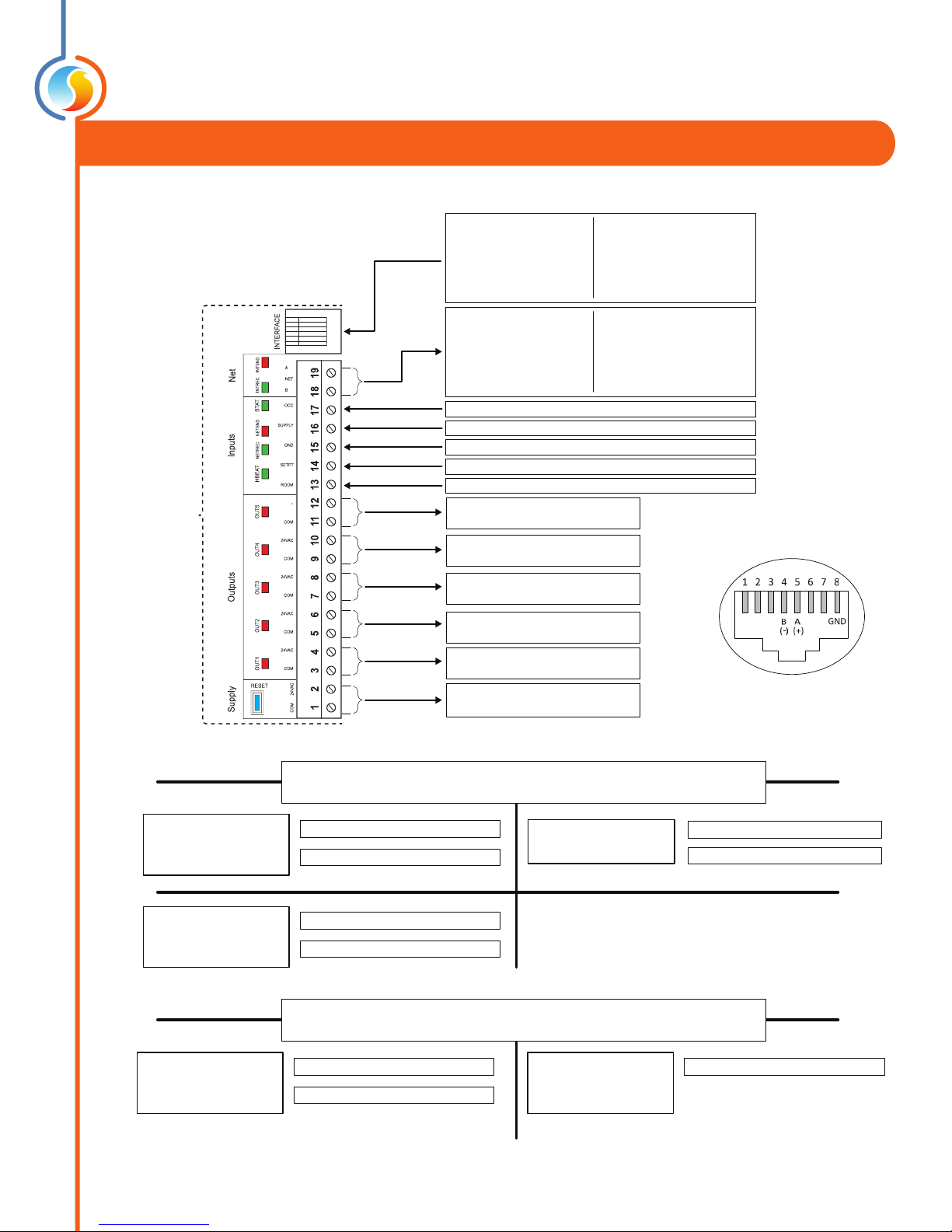
PL-M2000-RTU/RTUS (Zoning Rooftop Controller & Single-Zone Rooftop Controller)
24
VAC
AO 3 Bypass / VSD
AO 2 Economizer
AO 1 Preheating / Mod. Heat
DO 5 Heat (W2) / Exhaust Fan / Baseboard
DO 4 Heat (W1) / Preheat Perm.
DO 3 Cooling (Y2)
DO 2 Cooling (Y1)
DO 1 Fan (G)
Bottom Row:
Common for all outputs
Bottom Row:
Common for all inputs
Static pressure (0-5 / 1-5V) (1 / 1.5 / 2 / 2.5 in)
CO2 sensor (4-20 mA)
External dry contact for proof of fan
Zone temperature setpoint (0-10K potentiometer)
Zone temperature sensor (10K thermistor)
Supply air temperature sensor (10K thermistor)
Return air temperature sensor (10K thermistor)
Outside air temperature sensor (10K thermistor)
Controller’s power source
Unit’s R&Cterminals (24VAC)
Mixed air temp (10K therm) / Dry contact for clogged lter /
Dry contact for schedule override / Auxiliary Temp Input (10K thermistor)
RTUS
INT Port: ProLon Digital
Temperature Sensor
- OR -
Incoming RS485 Network
Communication (Modbus)
RTU
Incoming communication
from remote computer
or network controller
(Dual RJ45 and
Terminal Blocks)
RTUS
Net Port: ProLon Digital
Temperature Sensor
- OR -
Incoming RS485 Network
Communication (Modbus)
RTU
Outgoing network
communication
(to zones)
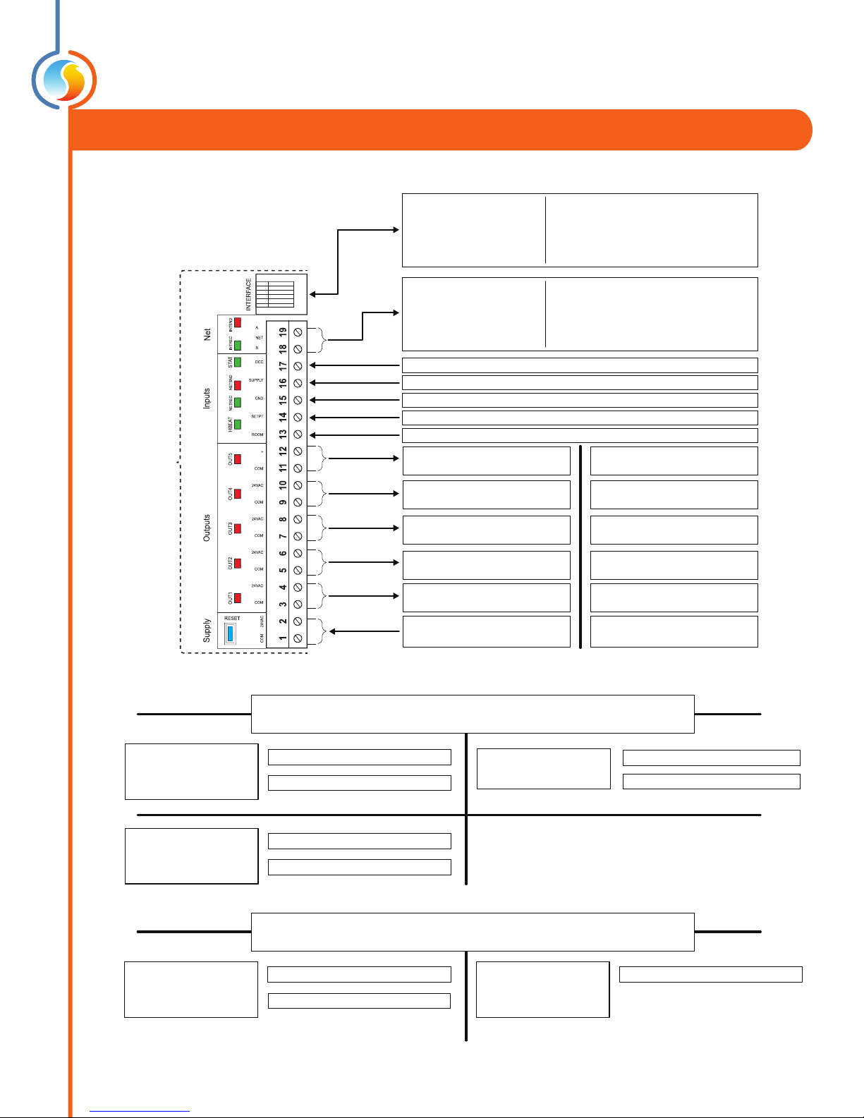
VC2000
C1000-VAV
T1100
Zone Demand
Unoccupied Override
C1000-HU
INFO RECEIVED FROM NETWORK
(PL-M2000-RTU)
Request for Fan
Dehumidication Demand
NC2000
Occupancy (Optional)
Outside Temp (Optional)
M2000-RTU
C1000-RTU
Outside Temp
NC2000
Occupancy (Optional)
Outside Temp (Optional)
INFO RECEIVED FROM NETWORK
(PL-M2000-RTUS)
24
VAC
AO 3 Bypass / VSD
AO 2 Economizer
AO 1 Preheating / Mod. Heat
DO 5 Heat (W2) / Exhaust Fan / Baseboard
DO 4 Heat (W1) / Preheat Perm.
DO 3 Cooling (Y2)
DO 2 Cooling (Y1)
DO 1 Fan (G)
Bottom Row:
Common for all outputs
Bottom Row:
Common for all inputs
Static pressure (0-5 / 1-5V) (1 / 1.5 / 2 / 2.5 in)
CO2 sensor (4-20 mA)
External dry contact for proof of fan
Zone temperature setpoint (0-10K potentiometer)
Zone temperature sensor (10K thermistor)
Supply air temperature sensor (10K thermistor)
Return air temperature sensor (10K thermistor)
Outside air temperature sensor (10K thermistor)
Controller’s power source
Unit’s R&Cterminals (24VAC)
Mixed air temp (10K therm) / Dry contact for clogged lter /
Dry contact for schedule override / Auxiliary Temp Input (10K thermistor)
RTUS
INT Port: ProLon Digital
Temperature Sensor
- OR -
Incoming RS485 Network
Communication (Modbus)
RTU
Incoming communication
from remote computer
or network controller
(Dual RJ45 and
Terminal Blocks)
RTUS
Net Port: ProLon Digital
Temperature Sensor
- OR -
Incoming RS485 Network
Communication (Modbus)
RTU
Outgoing network
communication
(to zones)
VC2000
C1000-VAV
T1100
Zone Demand
Unoccupied Override
C1000-HU
INFO RECEIVED FROM NETWORK
(PL-M2000-RTU)
Request for Fan
Dehumidication Demand
NC2000
Occupancy (Optional)
Outside Temp (Optional)
M2000-RTU
C1000-RTU
Outside Temp
NC2000
Occupancy (Optional)
Outside Temp (Optional)
INFO RECEIVED FROM NETWORK
(PL-M2000-RTUS)