Proluxe Endurance X1M User manual
Operations Manual
Endurance X1M Manual Dough Press w/ Mold - Model #: DP1100M
WWW.PROLUXE.COM
Version: 122820
Congratulations on your selection of
the Endurance X1M Manual Dough
Press with Mold Insert. Proluxe is a
leading manufacturer of food
preparation and cooking equipment
designed for the most demanding
commercial kitchens. Proluxe
equipment is a result of the highest
quality engineering and time-tested
design.
This manual includes installation,
operation, and maintenance
procedures for your new Endurance
X1M Dough Press. Please read this
manual carefully and keep it with
your machine for key to proper
operation and lasting service.
I N S T A L L A T I O N
Domestic
Use a separate 15 amp AC circuit. Only
industrial extension cords with proper wire
size should be used; size 16/3 wire for
distance up to 25 feet, and size 14/3 for
distance up to 50 feet.
International
Use a designated 16 amp AC circuit. Only
industrial extension cords with proper wire
size (2.5 sq. mm) shall be used. Make sure
there is a proper electrical wall outlet located
within reach of the cord and plug attached to
the press.
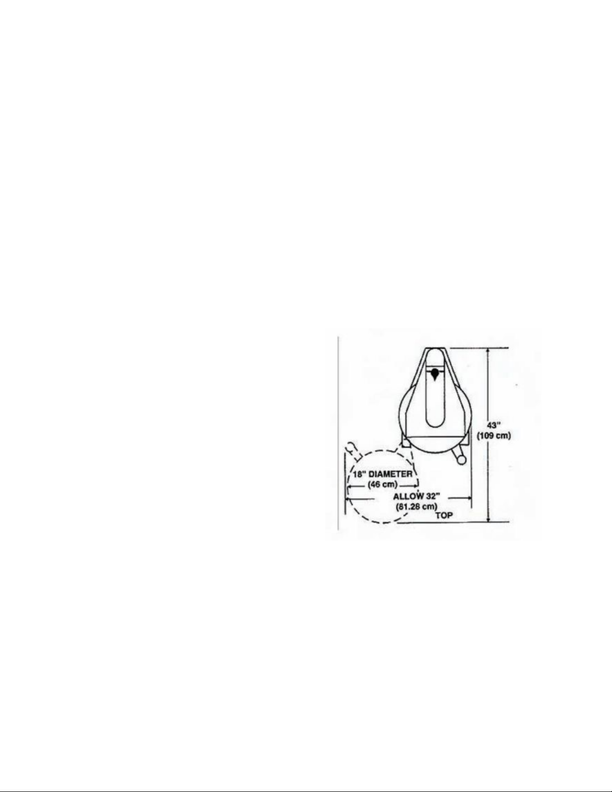
Then place the dough press in an area which
allows for “swing clearance” of the lower
platen. The lower platen of the press requires
room in which to rotate and suggest a
minimum of 36 inches of unobstructed space
in front of the press shown in FIG. 1.
FIG. 1
Limited Machine Warranty
Proluxe warrants this dough press machine,
when operated under normal conditions, to
be free from manufacturing defects in
material and workmanship for a period of
one year on parts and labor from the invoice
date.
1
This warranty will be effective only when
Proluxe authorizes the original purchaser to
return the product to the factory in Perris,
California freight prepaid and only when the
product, upon examination, has proven to be
defective.
This warranty does not apply to any machine
that has been subjected to misuse,
negligence or accident. Proluxe shall not be
liable for the injury, loss or damage, direct or
consequential, arising out of the use or the
inability to use the product. No claim of any
kind shall be greater in amount than the sale
price of the product or part to which claim is
made.
This is the sole warranty given by the
company, it is in lieu of any other warranties,
expressed or implied, in law or in fact,
including the warranties of merchantability
and fitness for a particular use, and is
accepted such by the purchaser in taking
delivery of this product.
S P E C I F I C A T I O N S
Electrical:
120V/60Hz/1425W/11.9 Amps
Also available; specify when ordering:
●Voltage: 120/208/240
●Amps: 12.5/11.1/16.5
●Watts: 1500/2300/1500
Includes: 72” cord and NEMA approved plug.
Shipping Weight:
190lbs. (76kg.)
I N T E R N A T I O N A L S Y M B O L S
Symboles internationaux
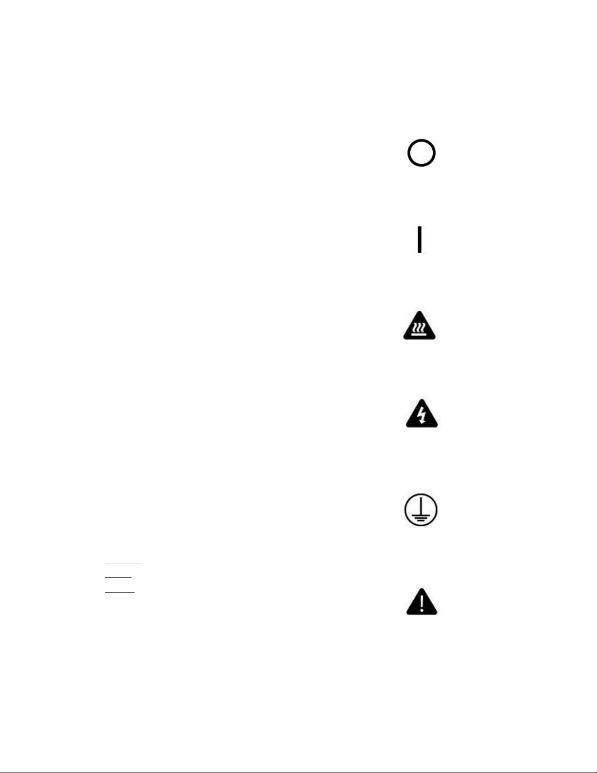
Power Off
éteindre
Power On
allumer
Hot Surface
surface chaude
Risk of Electrical Shock
Risque de choc électrique
Protective Earth Terminal
Borne de terre de protection
Caution - Warning
chaud - avertissement
2

S A F E T Y S U M M A R Y
Warning
To reduce the risk of electrical shock, do not
remove or open cover. No user-serviceable
parts inside. Refer servicing to qualified
personnel.
Avertissement
Pour réduire le risque de choc électrique, ne pas
retirer ou couvercle ouvert Aucune pièce
réparable par l’utillsateur, reportez-vous à du
personnel qualifié.
Warning
In case of power cord damage, do not
attempt to repair or replace the power cord.
Please contact the manufacturer or the local
distributor.
Avertissement
Pour une protection continue contre l’incendie
et de choc électrique, remplacer avec le même
type et calibre du fusible. Mis fusible
supplémentaire nominale max 3A, 120 Vac.
Warning
For continued protection against fire and
electric shock, replace with the same type
and rating fuse. Listed Supplemental Fuse
rated max 3A, 120Vac.
Avertissement
Pour une protection continue contre l’incendie
et de choc électrique, remplacer avec le même
type et calibre du fusible. Mis fusible
supplémentaire nominale max 3A, 120 Vac.
Caution Hot
Avoid touching hot surfaces while operating
the machine.
Attention à chaud
Évitez de toucher les surfaces chaudes lorsque
vous utilisez la machine.
Caution
When servicing or cleaning the machine,
make sure that the power cord is removed
from the wall socket.
During normal operation, the base of the
machine must be installed or placed above
the wall socket.
Avertissement
Lors de l'entretien ou du nettoyage de la
machine, assurez-vous que le cordon
d'alimentation est débranché de la prise murale.
3
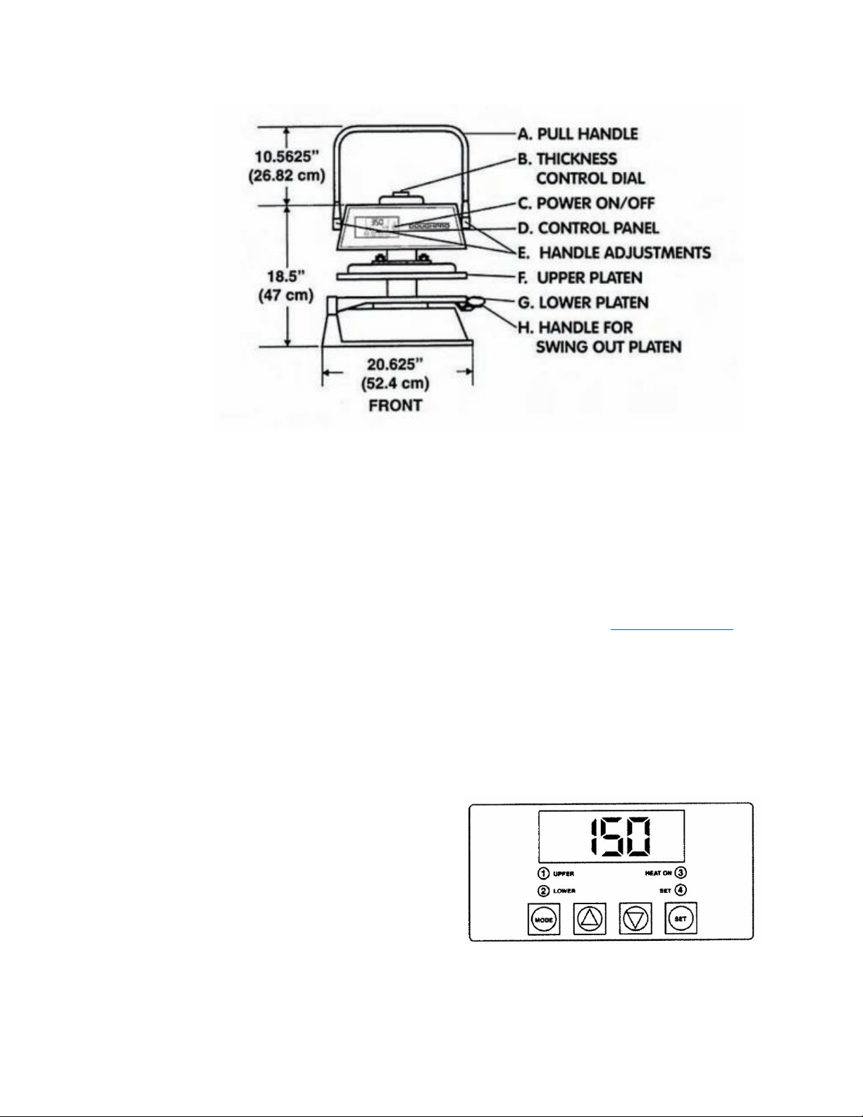
Familiarize yourself with the controls and
operating mechanisms before using the
Endurance X1.
(A) Pull-down pressing handle for raising
and lowering the upper platen. This
action forces the closing of the platens.
(B) Thickness control dial.
(C) On/Off button. The green light
above the button will illuminate when
powered on.
(D) Control Panel (See control board
operations)
(E) Handle Adjustments (See tightening
the pull-down handle)
(F) Upper Platen
(G) Lower Platen
(H) Handle for lower swing out platen.
Your dough press is equipped with a set of
rubber mounting pads.
If you would prefer a set of legs which would
raise your machine off the table 4 inches.
Please contact sales at [email protected] for
a set. Shipping charges may apply.
O P E R A T I O N T E M P E R A T U R E
& T I M E R C O N T R O L
FIG. A
4

Solid State Controller
This controller has three (3) control features:
1. Temperature – May be set from
100°-425°F (38°-163°C)
2. Time – Time may be set from 1 second to
10 minutes.
3. Counter – Cycle counter counts the
number of applications from 1 to 9999 (see
additional Notes – Counter).
4. “2 Lower” (Fig. A) Refers to models using
upper and lower heated surfaces.
Controller Operation
1. Viewing the Modes of Operation:
To view the set points of temperature, timer
and counter, press MODE button to view the
desired mode of operation.
2. Changing Temperature:
Press MODE button until temperature is
displayed.
Press and hold SET button while pressing the
UP (↑) and DOWN (↓) arrow buttons to
desired temperature setting.
Fahrenheit/Celsius Conversion:
The temperature controller can be
programmed to display either ºF or ºC. Press
the MODE button until the temperature is
displayed . Then push a hold the SET button
for 10 seconds.
3. Changing Time:
Press MODE button until time is displayed.
Press and hold SET button while pressing the
UP (↑) and DOWN (↓) arrow buttons to
desired timer setting.
4. Resetting the Counter:
Press MODE button until the
counter is displayed.
To reset the counter (# of cycles),
simultaneously push UP (↑) or DOWN (↓)
arrow buttons (approx. 5 seconds).
P R E S S O P E R A T I O N
Pressing Dough:
For best results, your dough should be
proofed before pressing, but it will also press
directly out of your refrigerator. Flour is not
required to press a crust and should not be
dusted on any part of the machine.
1. Check to see if you have the correct type
of electrical current or serious damage could
occur.
2. Press the power button, the green light
above will illuminate when powered on.
3. Set your desired temperature on the
control panel by using FIG. A and the
instructions above. We recommend a
temperature of 150ºF. Testing with your own
dough may desire a different setting.
Note
: Heat is provided in the upper platen is only
for purposes of enabling the dough to flow more
rapidly in the pressing cycle. The heat IS NOT
intended for baking
.
4. Set the thickness control which is located
on top of the machine. You can adjust this
control to your needs and requirements.
5

Note
: Diameter and thickness is determined
through experimenting with your own dough
and is a product of dough weight, temperature,
pressing time, and thickness setting.
5. Swing open the lower platen and
apply a quick spray of a good
water based food release on the lower
platen.
6. Place your pre-portioned ball of dough in
the approximate center of the lower platen.
Add another light spray to the top of the
dough ball.
7. Close the platen and pull the handle down
to begin pressing.
8. Hold the handle down and the timer will
actuate and, when the time cycle is
completed. Pull the handle back to starting
position and remove your product.
9. Remove the finished product by rotating
the lower platen until you have proper space
to remove your dough.
10. Remove the crust, place on a pan or peel,
add toppings and bake.
A D D I T I O N A L N O T E S
Tightening the Pull-down Handle
The pull-down pressing handle requires
adjustment periodically to prevent it from
free falling. Whenever the handle becomes
loose it can easily be tightened.
1. Using a 3/16” hex shaped Allen
wrench, insert in key slot located on
the right beneath the upper shroud.
2. Tighten until the press action of the
handle becomes firm.
R E C O M M E N D E D S E A S O N I N G
& C L E A N I N G P R O C E D U R E S
Before use you must properly season
your platens to prevent your dough from
sticking.
Tools Required:
●Food release
●Soapy water solution
●Washcloth
●Paper towels
DO NOT use steel wool or harsh abrasives, it
can cause costly damage.
1. Before cleaning make sure the
unit is turned off.
2. Spray lower platen with approved
food release/oil spray.
3. Wipe oil across lower platen with
paper towel.
4. Wipe oil across upper platen.
5. Mix a warm dish soap and water
solution.
6. Soak washcloth and wring to
remove excess water.
6

7. Wipe lower and upper platen with
damp cloth.
P R E V E N T A T I V E
M A I N T E N A N C E
Proluxe machines are relatively maintenance
free. For a long lifespan, the following
preventative maintenance should be
followed:
Daily Care:
1. Platens: Turn your machine off and allow
to cool down before attempting to clean.
These platens should only be cleaned with
mild soap and warm water then wiped off
with a clean, soft cloth or soft sponge.
2. Exterior surfaces: Wipe daily with mild
soap and warm water will do the job quite
nicely.
DO NOT use ice or cold water to cool the
unit down. This can cause platens to warp.
Piston Maintenance:
In order to ensure pop and trouble free
operation of the press piston, it is important
that the machine be lubricated once every
three months, under normal operation. High
volume users may require more frequent
lubrication.
Please follow these instructions:
1. Locate the grease port on the
machine. Machines with pull down
arms have a single grease port
located below the upper head on the
right side of the vertical post.
2. Place grease gun head against grease
port and apply enough pressure to
allow gun head to engage the grease
port.
3. Squeeze handle of grease gun. This
will force the grease into the piston.
The lubricant use must be USDA-H-I
authorized for food machinery. This lubricant
can be ordered through Proluxe, part #
110-002.
Service Problems:
Contact our factory at (800) 624-6717 (U.S.
only) or approved service agency. When
contacting the factory for information, parts
or service instructions, please provide the
serial number of the machine be provided.
This number can be found on the serial plate
located on the rear of the machine.
7

Endurance X1M Troubleshoot Guide - Model #: DP1100M
8
Problem
Cause
Action
Ref #
Power Button on
Digital Controller
face is depressed but
doesn’t turn on.
1. Power cord is not plugged in.
2. Circuit breaker is tripped off in the
site's breaker box.
3. Transformer has taken an
electrical surge and is damaged.
4. Check voltage on the secondary
side of the Transformer. If you read
12VDC then you are receiving
voltage to the controller.
5. Possible blown fuse.
1. Plug the power cord into wall
receptacle and power button.
2. Reset circuit breaker that the
grill is plugged into. Depress
Power Button to turn on.
3. Replace Transformer after you
check secondary side of
transformer. If working properly,
you should receive 12vdc.
4. Replace controller. Controller
should be on once the power
button is depressed.
5. Replace fuse.
68
-----
91
85
105
Digital Controller's
LED's are scrambled
or randomly erratic.
If when turning on,
the display will first
go to segment check
1. Possibly a component on the
Digital controller is damaged.
2. Control needs to reset.
1. Replace digital controller.
2. While unit is on unplug unit,
wait for 1 min. Then plug machine
on again and depress the power
button.
-----
85
Digital Controller on
startup goes through
LED segment check
(8888) then to
version # and then
loops back to to the
above reboot.
The relay driver on the digital control
may be blown.
Replace digital controller.
85
Digital display shows
PROB. No heat on
Upper Platen.
Sensor lost it's continuity as shown
on a muti-meter.
Disconnect prob that is open (no
continuity as shown on a multi-
meter. Must replace sensor
(RTD). Do not cut and splice new
sensor. Install new 2000 ohm
RTD sensor to under side of heat
platen and reconnect to the
controller.
41
When depressing the
The tactile buttons under the overlay
Carefully (no too much at one

9
tactile button on
digital controller,
nothing happens.
may be not close enough to activate.
Same goes if the buttons are already
pressed by overlay without
depressing button.
time to avoid fracturing the
traces on the controller) tighten
the nuts on the back of the
controller until button activate.
Same goes in reverse if buttons
are held down by the overlay.
Digital display shows
relay and particular
zone is overheating.
Beeper not
functioning or
intermittent beeper
sound.
1. The relay on the switched side is
not opening to regulate temperature.
2. Beeper on digital control board
failed.
1. Replace the relay.
2. Replace digital controller board
92
85
If setpoint is reached
but slightly off in
temperature.
Offset may need to be calibrated and
adjusted.
Call (800) 624-6717 ext. 129 for
instructions.
Heater platen
overheating
If the relay (depending on the year of
the model) on the coil side are
receiving 12vdc indicates the
controller is functioning properly. On
the switching side of the relay, is
there 120 vac going to the heater in
question. If there is no voltage on
the to the switching side of the relay
to the heaters, the relay is not
working properly.
Replace relay If the controller's
heat-on LED is not lit indicating
the controller is working
properly.
92
Dough not having
same thickness
across the press
dough.
Adjust upper platen for level press
Underneath the housing there is
4 stacked hex bolts sitting over
the upper platen attached to the
arm. The top bolts are called
locking bolts. The 4 larger hex
bolts below are adjustment bolts.
Break free the 4 locking bolts.
With an open end wrench adjust
the bolts (1/8 turn at a time).
After testing, tighten the locking
bolts making sure not to move
the larger adjustment bolts
11
And
12
10
11

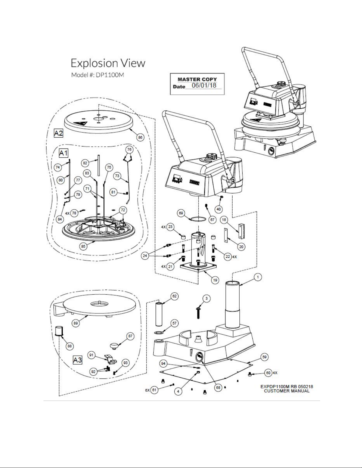
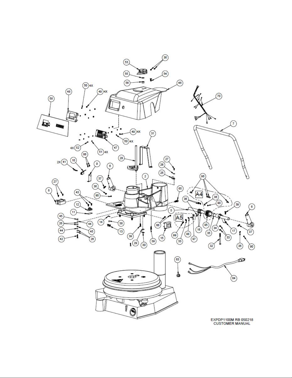
Endurance X1M Part List - Model #: DP1100M
12
ITEM
NO.
DESCRIPTION
DP1100MA
120 ~ AC
DP1100MB
240 ~ AC
DP1100MGB
240 ~ AC
DP1100MCEB
240 ~ AC
DP1100MCEC
220 ~ AC
QTY.
1
BASE ASSEMBLY
110931101
110931101
110931101
110931101
110931101
1
2
ARM MACHINED
11010212101
11010212101
11010212101
11010212101
11010212101
1
3
LOWER PLATEN STOP,
ASSEMBLY
110102130
110102130
110102130
110102130
110102130
1
4
NUT, HEX 3/8-16
NH3816
NH3816
NH3816
NH3816
NH3816
1
5
GEAR BAR
1109361
1109361
1109361
1109361
1109361
1
6
HANDLE SOCKET
11016650
11016650
11016650
11016650
11016650
2
7
HANDLE, PRESSURE
1109390
1109390
1109390
1109390
1109390
1
8
RELAY, SOLID STATE
MPR90217
MPR90217
MPR90217
MPR90217
MPR90217
1
9
MICROSWITCH BRACKET
1101021213
1101021213
1101021213
1101021213
1101021213
1
10
MICRO SWITCH
V15G31C25K
V15G31C25K
V15G31C25K
V15G31C25K
V15G31C25K
1
11
MARKER STRIP #2
MS6992
MS6992
MS6992
MS6992
MS6992
1
12
BLOCK, TERMINAL ASSY 2
STAGE
11096914
11096914
11096914
11096914
11096914
1
13
FUSE HOLDER 1 AMP
MPPF708
MPPF708
MPPF708
MPPF708
MPPF708
1
14
FUSE BUSS 1 AMP
MPPF701R
MPPF701R
MPPF701R
MPPF701R
MPPF701R
1
15
TRANSFORMER
11096975
11096975
11096975
11096975
11096975
1
16
COLLAR, GEAR BAR
11013183
11013183
11013183
11013183
11013183
2
17
ASSEMBLY, TENSION STRAP
11041663
11041663
11041663
11041663
11041663
1
18
RACK, GEAR
1109380
1109380
1109380
1109380
1109380
1
19
ASSEMBLY, PISTON
11018974
11018974
11018974
11018974
11018974
1
20
SHIM, GEAR RACK
110144120
110144120
110144120
110144120
110144120
1
21
BOLT, LEVEL ADJUSTMENT
1109367
1109367
1109367
1109367
1109367
4
22
BOLT, HEX 5/16-18 X 1 3/4" GR5
BH51618134G
5
BH51618134G
5
BH51618134G
5
BH51618134G
5
BH51618134G
5
4
23
CAP, VINYL (ADJUSTMENT
SCREWS)
SC0687
SC0687
SC0687
SC0687
SC0687
4
24
SCREW, SOCKET HEAD 3/8-16 X
3/4
SSH381634
SSH381634
SSH381634
SSH381634
SSH381634
2
25
CLAMP, CABLE 3/8
CC38
CC38
CC38
CC38
CC38
1
26
WASHER, SAE #8
WSAE8
WSAE8
WSAE8
WSAE8
WSAE8
5
27
SCREW, PHILLIPS PAN HEAD
8-32 X 3/8
SP83238
SP83238
SP83238
SP83238
SP83238
3
28
CAM RAMP ASSEMBLY
1109310
1109310
1109310
1109310
1109310
1
29
WASHER, WAVE .505 I.DX.750
O.D, X .045
5806282
5806282
5806282
5806282
5806282
1
30
CLIP "E" RETAINING 1/2
MPSC240
MPSC240
MPSC240
MPSC240
MPSC240
1

13
31
BRACKET, HOUSING ASSEMLBY
110144130
110144130
110144130
110144130
110144130
1
32
SCREW, SOCKET HEAD 1/4-20 X
3 1/4
SSH1420314
SSH1420314
SSH1420314
SSH1420314
SSH1420314
1
33
NUT, HEX 1/4-20
NH1420
NH1420
NH1420
NH1420
NH1420
3
34
BUSHING, TENSION STRAP
11018966
11018966
11018966
11018966
11018966
1
35
BUSHING, SPACER
11024369
11024369
11024369
11024369
11024369
1
36
SCREW, SET 1/4-20 X 3/8
SST142038
SST142038
SST142038
SST142038
SST142038
6
ITEM
NO.
DESCRIPTION
DP1100MA
120 ~ AC
DP1100MB
240 ~ AC
DP1100MGB
240 ~ AC
DP1100MCEB
240 ~ AC
DP1100MCEC
220 ~ AC
QTY.
37
SCREW, SET SOCKET HEAD
1/4-20 X 7/8
SST142078
SST142078
SST142078
SST142078
SST142078
2
38
SCREW, PHILLIPS PAN 2-56 X
1/4
SP25614
SP25614
SP25614
SP25614
SP25614
1
39
SCREW, BUTTON HEAD
1/4-20X3/4
SB142034
SB142034
SB142034
SB142034
SB142034
3
40
FITTING, ZERK 1/4-28
B792
B792
B792
B792
B792
1
41
SCREW, ROUND HEAD 4-40 X
5/8 SLOTTED
SR44058
SR44058
SR44058
SR44058
SR44058
2
42
SCREW, PAN HEAD 8-32 X 1
SP8321
SP8321
SP8321
SP8321
SP8321
1
43
SCREW, PAN HEAD PHILLIPS
8-32 X 1/2
SP83212
SP83212
SP83212
SP83212
SP83212
2
44
WASHER, INTERNAL TOOTH
LOCK #8
WLIT8
WLIT8
WLIT8
WLIT8
WLIT8
2
45
NUT, HEX 8-32
NH832
NH832
NH832
NH832
NH832
2
46
HOUSING MACHINED
11017815422
01
11017815422
01
11017815422
01
11017815422
01
11017815422
01
1
47
DIGITAL CONTROL
11096905211
11096905211
11096905211
11096905211
11096905211
1
48
ASSEMBLY, CONTROL FACIA
11086027
11086027
11086027
11086027
11086027
1
49
NUT, HEX 6-32
NH632
NH632
NH632
NH632
NH632
8
50
WASHER, INTERNAL TOOTH
LOCK #6
WLIT6
WLIT6
WLIT6
WLIT6
WLIT6
8
51
WASHER, STEEL
311150019
311150019
311150019
311150019
311150019
4
52
NYLON SPACER, 1/4 X .141 X
9/32 LONG
110969111
110969111
110969111
110969111
110969111
4
53
KNOB, THICK/THIN MACHINED
1109309
1109309
1109309
1109309
1109309
1
54
SCREW, SOCKET FLAT HEAD
1/4-20 X 3/4
SF142034
SF142034
SF142034
SF142034
SF142034
1
55
SHIM WASHER
WS12031
WS12031
WS12031
WS12031
WS12031
1
56
BUSHING, FLANGE
212NN014200
00
212NN014200
00
212NN014200
00
212NN014200
00
212NN014200
00
1
57
SHIM, LOWER PLATEN
11037932205
5
11037932205
5
11037932205
5
11037932205
5
11037932205
5
1
58
OVERLAY, DIGITAL CONTROL
PANEL
ODP1100
ODP1100
ODP1100
ODP1100
ODP1100
1

14
59
COVER PLATE, BASE
11010954
11010954
11010954
11010954
11010954
1
60
FEET, RUBBER
RF209
RF209
RF209
RF209
RF209
4
61
BOLT, HEX 8-32 X 1/4
BH83214
BH83214
BH83214
BH83214
BH83214
6
62
POST, LOWER PLATEN
11015960
11015960
11015960
11015960
11015960
1
63
CABLE STRAIN RELIEF
MPSS168
MPSS168
MPSS168
MPSS168
MPSS168
1
64
POWER CORD
110969174
110969175
DP149203
MPPW202
MPPW202
1
65
SCREW, SOCKET HEAD 3/8-16 X
1
SSH38161
SSH38161
SSH38161
SSH38161
SSH38161
1
ITEM
NO.
DESCRIPTION
DP1100MA
120 ~ AC
DP1100MB
240 ~ AC
DP1100MGB
240 ~ AC
DP1100MCEB
240 ~ AC
DP1100MCEC
220 ~ AC
QTY.
66
SCREW, PHILLIPS PAN HEAD
8-32 X 1/4
SP83214
SP83214
SP83214
SP83214
SP83214
4
67
DETENT, PLUNGER SPRING
3/8-16
MPSP134
MPSP134
MPSP134
MPSP134
MPSP134
1
68
DECAL USA STICKER
DPROUSA
DPROUSA
DPROUSA
DPROUSA
DPROUSA
1
69
ORING, #2-28 N-70, PISTON
238N70
238N70
238N70
238N70
238N70
1
70
WIRE HARNESS
110560051
110560051
110560051
110560051
110560051
1
71
WIRE, TGGT, 14GA. (HEATER)
110069
110069
110069
110069
110069
7 FT.
72
TFE SHRINK TUBING
110131
110131
110131
110131
110131
.33
FT.
73
SENSOR ASSEMLBY
110949110
110949110
110949110
110949110
110949110
1
74
TERMINAL, RING #8
1604
1604
1604
1604
1604
1
75
14-16 GA #10 FORK TERMINAL
INSUL.
1626
1626
1626
1626
1626
1
76
TERMINAL Q.D. 3/16 X 18/22GA.
2280
2280
2280
2280
2280
2
77
SCREW, PAN HEAD 6-32 X 1/4
SP63214
SP63214
SP63214
SP63214
SP63214
1
78
WASHER, SAE 5/16
WSAE516
WSAE516
WSAE516
WSAE516
WSAE516
4
79
WASHER, SAE #6
WSAE6
WSAE6
WSAE6
WSAE6
WSAE6
1
80
WIRE, TFE 14GA. GREEN
WTFE14G
WTFE14G
WTFE14G
WTFE14G
WTFE14G
3.08
FT.
81
SCREW, SET 3/8-16 X 1/2
SST381612
SST381612
SST381612
SST381612
SST381612
1
82
SLEEVING, PVC WIRE
OPVC1050
OPVC1050
OPVC1050
OPVC1050
OPVC1050
1.33
FT.
83
TERMINAL, FEMALE MOLEX
MPSQ100
MPSQ100
MPSQ100
MPSQ100
MPSQ100
1
84
TERMINAL, RING #6
1601HT
1601HT
1601HT
1601HT
1601HT
1
86
SHROUD, UPPER PLATEN
1109336
1109336
1109336
1109336
1109336
1
87
KNOB, SWING AWAY
110017
110017
110017
110017
110017
1
88
FLANGED BUSHING
MACHINED
110102167
110102167
110102167
110102167
110102167
1
90
SCREW, SET 1/4-20 X 1/4"
SST142014
SST142014
SST142014
SST142014
SST142014
3
91
HANDLE LOWER PLATEN
1106301
1106301
1106301
1106301
1106301
1

15
92
SCREW, BUTTON HEAD 1/4-20
X 3/4
SB142034
SB142034
SB142034
SB142034
SB142034
2
93
SCREW, BUTTON HEAD 1/4-20
X 5/8
SB142058
SB142058
SB142058
SB142058
SB142058
1
94
WASHER, SAE 3/8
WSAE38
WSAE38
WSAE38
WSAE38
WSAE38
1
95
PINION GEAR ASSEMBLY
1109360
1109360
1109360
1109360
1109360
1
ITEM
NO.
DESCRIPTION
DP1100MA
120 ~ AC
DP1100MB
240 ~ AC
DP1100MGB
240 ~ AC
DP1100MCEB
240 ~ AC
DP1100MCEC
220 ~ AC
QTY.
96
KEYWAY, #9 3/16 X 3/4
KW931634
KW931634
KW931634
KW931634
KW931634
4
97
BRACKET, MICRO SWITCH
110200019
110200019
110200019
110200019
110200019
1
98
WASHER, SPLIT LOCK, 1/4
WL14
WL14
WL14
WL14
WL14
1
99
SCREW, SET 1/4-20 X 3/4 CONE
POINT
SST142034CP
SST142034CP
SST142034CP
SST142034CP
SST142034CP
1
100
MANUAL DP1100M
MDP1100M
MDP1100M
MDP1100M
MDP1100M
MDP1100M
1
A1
UPPER PLATEN WIRE ONLY
110074120K
110074240K
110074240K
110074240K
110074220K
1
A2
UPPER PLATEN COMPLETE
ASSEMBLY
110074120AK
110074240AK
110074240AK
110074240AK
110074220AK
1
A3
LOWER PLATEN ASSEMBLY
11076632K
11076632K
11076632K
11076632K
11076632K
1
A4
PINION GEAR ASSEMBLY
1109360K
1109360K
1109360K
1109360K
1109360K
1
A5
KIT, MICRO SWITCH BRACKET
ASSEMBLY
110200019K
110200019K
110200019K
110200019K
110200019K
1
16

Warranty & Return Policy
Proluxe warrants all products manufactured
by it against defects in workmanship or
materials from the date of purchase for a
period of 1 year on parts and labor. This
warranty applies to only equipment
purchased and used in the United States.
Warranty period shall begin when equipment
ships. Warranty travel will only be covered
for 60 miles.
ALL WARRANTY SERVICE CALLS MUST BE
APPROVED BY PROLUXE. IF THIS
PROCEDURE IS NOT FOLLOWED,
WARRANTY SERVICE WILL NOT BE
COVERED. WARRANTY SERVICE WILL BE
PAID ON STRAIGHT TIME, OVERTIME
WILL NOT BE COVERED.
E X C L U S I O N S
Wood & Gas Fired Ovens
Warranty applies to the main body of the
oven being steel / refractory and insulation
shall be free from defects in materials and
workmanship for a period of four years from
the date of purchase. The gas equipment
shall be free from defects in materials and
workmanship for a period of one (1) year
from the date of purchase. Lifetime warranty
against cracks on the oven floor.
Special Order Equipment and
Accessories
Cannot be canceled and are not returnable
unless defective within the terms of this
warranty.
In no event shall Proluxe be liable for
consequential damages arising out of the
failure of any of its products if operated
improperly or caused by normal wear or
damaged by operator abuse.
Limited Lifetime Warranty on
Heating Elements
If replacement is needed, Proluxe will send
the new part at no charge but labor will not
be covered unless the unit is still under the 1
year manufacturer warranty.
R E T U R N E D M E R C H A N D I S E
P O L I C Y
Should it become necessary to return any of
the company’s products, the following
instructions must be adhered to: First,
contact our customer service department for
approval and a return authorization number.
Please have the serial number of your item
available at that time. All merchandise must
be shipped freight prepaid by customer or
service agency. Subject to the inspection of
the product by the company, a restocking
charge of 20% of the Net purchased price
paid to Proluxe will be assessed.
Merchandise may not be returned for credit
without prior written approval of Proluxe.
Collect shipments will not be accepted. No
returns after 60 days of original shipment
17

date on machines. Purchased parts may not
be returned after 30 days. If upon inspection
by Proluxe or its authorized agent it is
determined the equipment has not been used
in an appropriate manner, has been modified,
or has not been properly maintained, or has
been subject to misuse, misapplication,
neglect, abuse, accident, unauthorized
modification, damage during transit, delivery,
fire, flood, act or war, riot or act of God, then
this warranty shall be deemed null and void.
T E R M S & C O N D I T I O N S
1. Price List prices are suggested retail prices
and are shown in U.S. Dollars.
2. Terms of Payment: 1% 10 days, NET 30
days.
3. New Accounts: Satisfactory credit
information must be provided before open
account status can be extended.
Unless agreed otherwise, all shipments will
be made C.O.D., Cash in advance.
4. Pricing: Prices, specifications, model
numbers, capacities and accessories are
subject to change without notice.
5. Freight/Routing: Method of shipment will
be determined by Proluxe unless otherwise
advised by purchaser.
6. Damaged Claims: All merchandise shipped
at purchaser’s risk. Inspection must be made
by purchaser at time goods are received. If
goods are damaged, the PURCHASER shall
request that the agent of the transportation
company make a written notation on the
proper shipping documents immediately and
then file a claim for damages.
Note
: Goods damaged in shipping are
non-returnable.
7. Returns: Machines may not be returned
after 60 days. Purchased parts may not be
returned after 30 days. A restocking fee of
20% will be assessed on non-warranty
returns.
8. Taxes: Prices indicated herein DO NOT
include State, Federal, Local or foreign taxes
or duties, nor do they include fees, permits,
insurance or other levies, all of which are the
responsibility of the purchaser.
9. All orders are subject to acceptance by
Proluxe.
10. Possession of this price list shall not be
considered an offer to sell.
18
Other manuals for Endurance X1M
1
This manual suits for next models
1
Table of contents
Other Proluxe Kitchen Appliance manuals


