Proluxe Impact X1M User manual
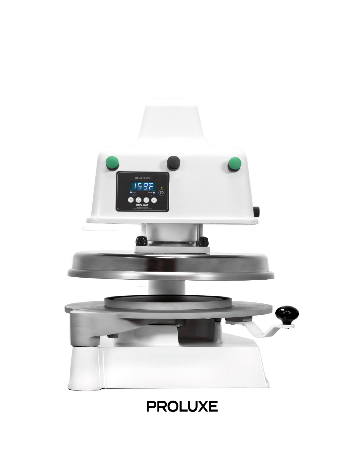
Operations Manual
Impact X1M - Electro-mechanical Automatic Dough Press w/ Embedded Mold
Model #: DP3300M
WWW.PROLUXE.COM
Version: 51219

Congratulations on your selection of
the Impact X1M Dough Press with
an embedded mold. Proluxe is a
leading manufacturer of food
preparation and cooking equipment
designed for the most demanding
commercial kitchens. Proluxe
equipment is a result of the highest
quality engineering and time-tested
design.
This manual includes installation,
operation, and maintenance
procedures for your new Impact
X1M Dough Press. Please read this
manual carefully and keep it with
your machine for proper operation
and lasting service.
I N S T A L L A T I O N
Domestic
Use a separate 30 amp AC circuit. Only
industrial extension cords with proper wire
size should be used; size 16/3 wire for
distance up to 25 feet, and size 14/3 for
distance up to 50 feet.
International
Use a designated 16 amp AC circuit. Only
industrial extension cords with proper wire
size (2.5 sq. mm) shall be used. Make sure
there is a proper electrical wall outlet located
within reach of the cord and plug attached to
the press.
Make sure there is a proper electrical wall
outlet located within reach of the cord and
plug attached to the press. Place the press in
an area which allows for “swing clearance” of
the lower platen plus vertical and horizontal
clearance of the press itself.
Limited Machine Warranty
Proluxe warrants this dough press machine,
when operated under normal conditions, to
be free from manufacturing defects in
material and workmanship for a period of
one year on parts and labor from the invoice
date.
This warranty will be effective only when
Proluxe authorizes the original purchaser to
return the product to the factory in Perris,
California freight prepaid and only when the
product, upon examination, has proven to be
defective. This warranty does not apply to
any machine that has been subjected to
misuse, negligence or accident. Proluxe shall
not be liable for the injury, loss or damage,
direct or consequential, arising out of the use
or the inability to use the product. No claim
of any kind shall be greater in amount than
the sale price of the product or part to which
claim is made.
This is the sole warranty given by the
company, it is in lieu of any other warranties,
expressed or implied, in law or in fact,
1
including the warranties of merchantability
for a particular use, and is accepted by the
purchaser in taking delivery of this product.
General Operation:
S P E C I F I C A T I O N S
Electrical:
120V/50-60Hz/1450W/12.5 Amps
Requires 30 AMP outlet
Also available; specify when ordering:
●Voltage: 120/240
●Amps: 12.5/6.04
●Watts: 1450
Shipping Weight:
200lbs. (82kg.) – DP3300M
Includes: 72” cord and 6-30P NEMA
approved plug.
S A F E T Y S U M M A R Y
Warning
In case of power cord damage, do not
attempt to repair or replace the power cord.
Please contact the manufacturer or the local
distributor.
Avoid touching hot surfaces while
operating the machine.
Caution
During normal operation, the base of the
machine must be installed or placed above
the wall socket. When servicing or cleaning
the machine, make sure that the power cord
is removed from the wall socket.
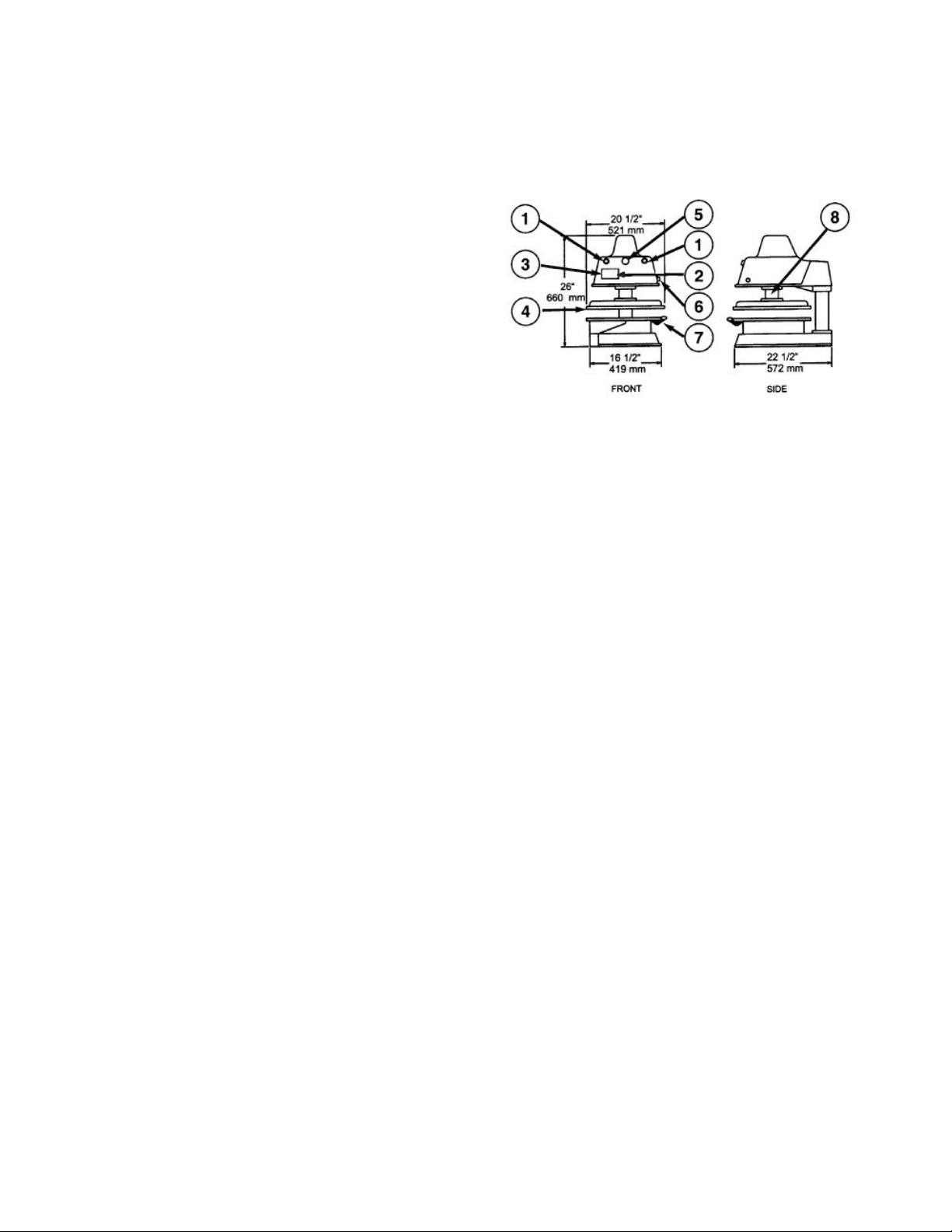
1. Piston Activation Buttons (2)
2. On/Off Power Switch
3. Digital Temperature & Time Control:
Factory default temperature setting 200°F.
4. Upper Platen:
Heated to help the dough flow faster and
evenly.
5. Disengage Switch:
Releases upper platen in case of emergency.
6. Thickness Control Dial:
Controls the thickness of the dough. (Not
available on dough presses with embedded
molds.)
7. Lower Platen:
Swings out for easy removal of flattened
dough.
8. Grease Port:
Using a standard grease gun, squeeze a food
approved, high temperature grease into the
port.
2
Exterior Finish:
Highly resistant white, high gloss powder
coat, approved for use with food products.
Molds are probrite coated anti-stick
surfaces.
O P E R A T I O N T E M P E R A T U R E
& T I M E R C O N T R O L
FIG. A
Solid State Controller
This controller has three control features:
1. Temperature – May be set from
100°F-425°F (38°-163°C) Factory default is
200ºF.
2. Time – Time may be set from 1 second to
10 minutes.
3. Counter – Cycle counter counts the
number of applications from 1 to 9999 (see
additional Notes – Counter).
4. 2 Lower (Fig. A) Refers to models using
upper and lower heated surfaces.
Controller Operation
1. Viewing the Modes of Operation:
To view the set points of temperature, timer
and counter, press MODE button to view the
desired mode of operation.
2. Changing Temperature:
Press MODE button until temperature is
displayed.
Press and hold SET button while pressing the
UP (↑) and DOWN (↓) arrow buttons to
desired temperature setting.
Fahrenheit/Celsius Conversion:
The temperature controller can be
programmed to display either ºF or ºC. Press
the MODE button until the temperature is
displayed . Then push a hold the SET button
for 10 seconds.
3. Changing Time:
Press MODE button until time is displayed.
Press and hold SET button while pressing the
UP (↑) and DOWN (↓) arrow buttons to
desired timer setting.
2. Set the timer in accordance with the
following information:
●2-4 seconds –For warm dough with
moderate yeast content.
●2-6 seconds – For room temperature
dough with moderate yeast content.
●6-8 seconds – For cold dough right
out of the refrigerator with low yeast
content.
4. Resetting the Counter:
Press MODE button until the counter is
displayed.
To reset the counter (# of cycles),
simultaneously push UP (↑) or DOWN (↓)
arrow buttons (approx. 5 seconds).
3

D O U G H P R E S S I N G
O P E R A T I O N S
Pressing Dough:
For best results, your dough should be
proofed before pressing, but it will also press
directly out of your refrigerator. Flour is not
required to press a crust and should NOT be
dusted on any part of the machine.
1. Check to see if you have the correct type
of electrical current or serious damage could
occur.
2. Press the power button, the green light
above will illuminate when powered on.
3. Set your desired temperature on the
control panel by using FIG. A and the
instructions above. We recommend a
temperature of 150ºF. Testing with your own
dough may desire a different setting.
Note
: Heat is provided in the upper and lower
platens enable the dough to flow more rapidly in
the pressing cycle. The heat IS NOT intended for
baking
.
4. Swing open the lower platen and apply a
quick spray of a good water based food
release on the platen.
5. Place your pre-portioned ball of dough in
the approximate center of the lower platen
mold. Add another spray to the top of the
dough ball.
6. Close the platen and, with both hands,
press the two green buttons on the machine
simultaneously.
7. Press the green buttons until it beeps then
release both buttons. The timer will actuate
and, when the time cycle is completed, the
platens will release automatically. (Timer is
factory preset for six (6) seconds.
Instructions to change the timer is found
above under Controller Operations.)
9. Remove the finished product by rotating
the upper platen until you have proper space
to remove your dough.
10. Remove the crust, place on a pan or peel,
add toppings and bake.
R E C O M M E N D E D S E A S O N I N G
& C L E A N I N G P R O C E D U R E S
Before use you must properly season your
platens to prevent your dough from sticking.
Tools Required:
●Food release
●Soapy water solution
●Washcloth
●Paper towels
DO NOT use steel wool or harsh abrasives, it
will you will cause costly damage.
1. Before cleaning make sure the unit is
turned off.
2. Spray lower platen with approved
food release/oil spray.
3. Wipe oil across lower platen with
paper towel.
4

4. Wipe oil across upper platen.
5. Mix a warm dish soap and water
solution.
6. Soak washcloth and wring to remove
excess water.
7. Wipe lower and upper platen with
damp cloth.
P R E V E N T A T I V E
M A I N T E N A N C E
Proluxe machines are relatively maintenance
free. For a long lifespan, the following
preventative maintenance should be
followed:
Daily Care:
1. Platens: Turn your machine off and allow
to cool down before attempting to clean.
These platens should only be cleaned with
mild soap and warm water then wiped off
with a clean, soft cloth or soft sponge.
2. Exterior surfaces: Wipe daily with mild
soap and warm water.
DO NOT use ice or cold water to cool the
unit down. This can cause platen to warp.
Piston Maintenance:
In order to ensure pop and trouble free
operation of the press piston, it is important
that the machine be lubricated once every
three months, under normal operation. High
volume users may require more frequent
lubrication.
Please follow these instructions:
1. Locate the grease port on the
machine. Machines will pull down
arms has a single grease port located
below the upper head on the right
side of the vertical post.
2. Place grease gun head against grease
port and apply enough pressure to
allow gun head to engage the grease
port.
3. Squeeze handle of grease gun. This
will force the grease into the piston.
The lubricant use must be USDA-H-I
authorized for food machinery. This lubricant
can be ordered through Proluxe, part #
110-002.
Service Problems:
Contact our factory at (800) 624-6717 (U.S.
only) or approved service agency. When
contacting the factory for information, parts
or service instructions, please provide the
serial number of the machine be provided.
This number can be found on the serial plate
located on the rear of the machine.
5

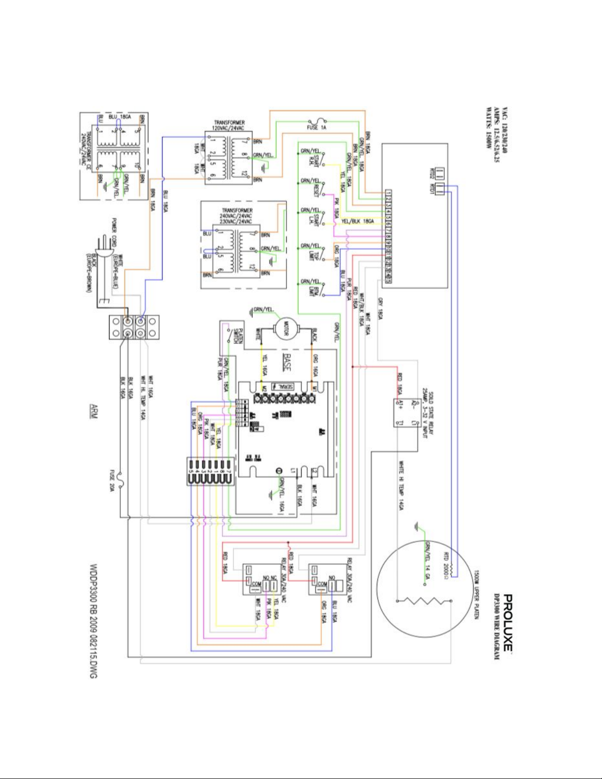
Impact X1M Troubleshoot Guide - Model #: DP3300M
Problem
Cause
Action
Ref #
Power button on
digital controller face
is depressed but
doesn’t turn on.
1. Power cord is not plugged in.
2. Circuit breaker is tripped off in the
site's breaker box.
3. Transformer has taken an
electrical surge and is damaged.
4. Check voltage on the secondary
side of the Transformer. If you read
12VDC then you are receiving
voltage to the controller.
5. Possible blown fuse.
1. Plug the power cord into wall
receptacle and power button.
2. Reset circuit breaker that the
grill is plugged into. Depress
Power Button to turn on.
3. Replace Transformer after you
check secondary side of
transformer. If working properly,
you should receive 12vdc.
4. Replace controller. Controller
should be on once the power
button is depressed.
5. Replace fuse.
68
-----
91
85
105
Digital controller's
LED's are scrambled
or randomly erratic.
If when turning on,
the display will first
go to segment check
1. Possibly a component on the
Digital controller is damaged.
2. Control needs to reset.
1. Replace digital controller.
2. While unit is on unplug unit,
wait for 1 min. Then plug machine
on again and depress the power
button.
85
----
Digital controller on
startup goes through
LED segment check
(8888) then to
version # and then
loops back to to the
above reboot.
The relay driver on the digital control
may be blown.
Replace digital controller.
85
Digital display shows
PROB. No heat on
Upper Platen.
Sensor lost it's continuity as shown
on a muti-meter.
Disconnect prob that is open (no
continuity as shown on a multi-
meter. Must replace sensor
(RTD). Do not cut and splice new
sensor. Install new 2000 ohm
RTD sensor to under side of heat
platen and reconnect to the
controller.
41
When depressing the
tactile button on
digital controller,
nothing happens.
The tactile buttons under the overlay
may be not close enough to activate.
Same goes if the buttons are already
pressed by overlay without
Carefully (no too much at one
time to avoid fracturing the
traces on the controller) tighten
the nuts on the back of the
6

depressing button.
controller until button activate.
Same goes in reverse if buttons
are held down by the overlay.
Digital display shows
relay and particular
zone is overheating.
1. The relay on the switched side is
not opening to regulate temperature.
1. Replace the relay.
92
Beeper not
functioning or
intermittent beeper
sound.
1. Beeper on digital control board
failed.
1. Replace digital controller
board
85
Power is on but hear
a leaking of air under
the lower platen /
swing arm while
press is idle.
The O'rings are worn allowing the air
to pass through the cylinder
The cylinder needs o-rings,
gasket
and new cylinder grease. Request
instruction sheet and need to
order P/N 110033 for the kit.
----
Press does not close
when pressing the
two, green, start
buttons
Did not simultaneously press the
start buttons exactly at the same
time.
Try pressing both buttons exactly
at the same time. This is a
anti-tiedown safety feature.
2
If setpoint is reached
but slightly off in
temperature.
Offset may need to be calibrated and
adjusted.
Call (800) 624-6717 ext. 129 for
instructions.
----
After activation
lower platen and
when the cycle is
complete, the lower
platen either is very
slow coming down or
doesn’t come down
at all.
The Mufflers on the Solenoid Valve
are dirty and now allowing air from
passing though.
Replace both Solenoid Valve
mufflers.
----
Upon activation, the
lower platen is slow
to come up and
down.
Filter encased in a black housing in
the back of the machine is dirty.
Replace filter.
---
Heater platens
overheating
If the relay (depending on the year of
the model) on the coil side are
receiving 12vdc indicates the
controller is functioning properly. On
the switching side of the relay, is
there 120 vac going to the heater in
question. If there is no voltage on
the to the switching side of the relay
to the heaters, the relay is not
Replace relay If the controller's
heat-on LED is not lit indicating
the controller is working
properly.
92
7

working properly.
8
9
10
11

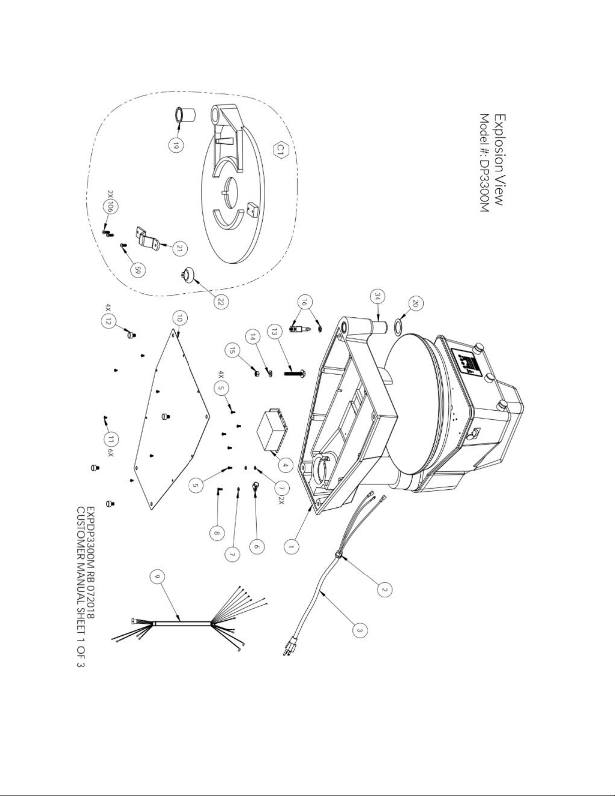
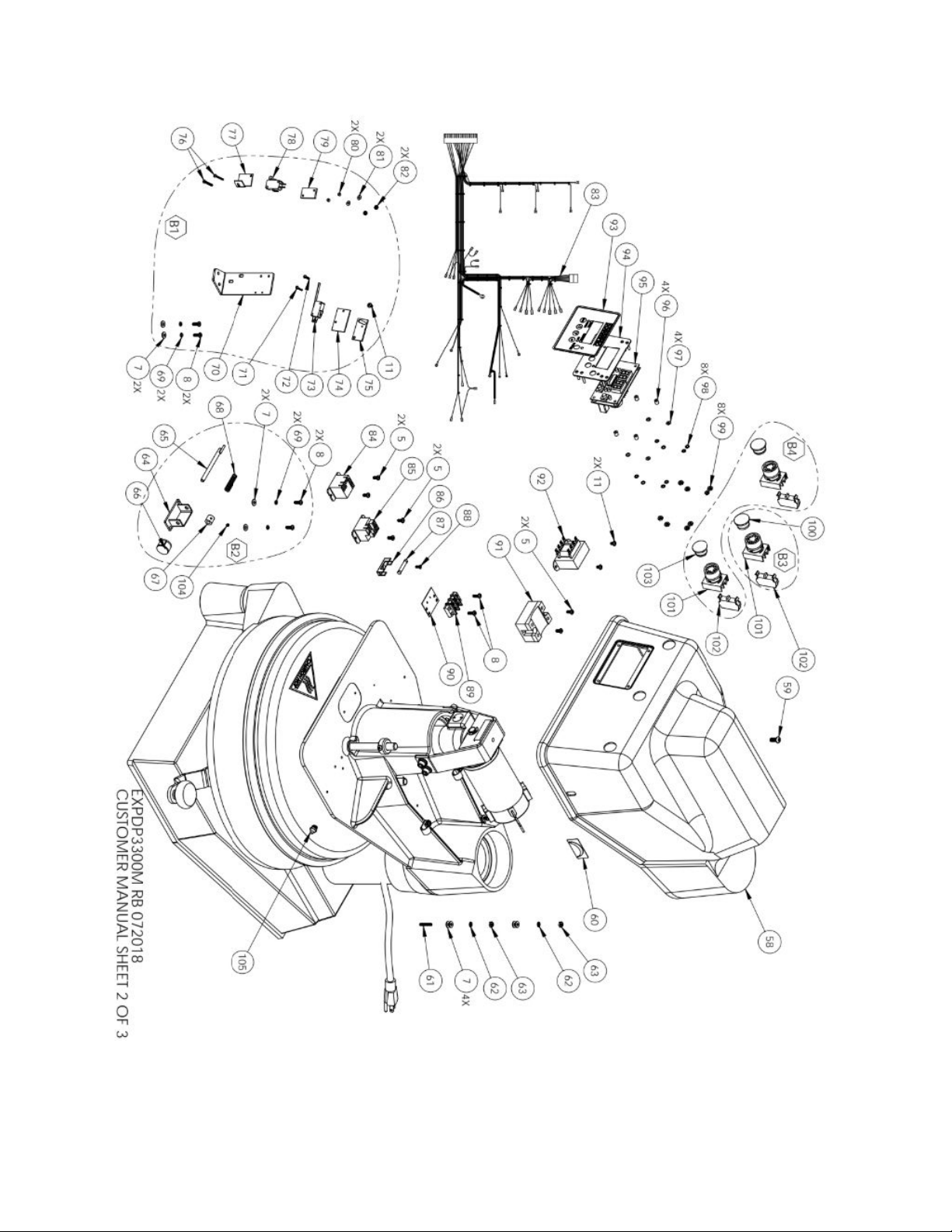
Impact X1M Part List - Model #: DP3300M
ITEM
#
DESCRIPTION
DP3300MA
DP3300MB
DP3300MAU
B
DP3300MAU
C
DP3300MGB
DP3300MGC
DP3300MCE
B
QTY
1
BASE ASSEMBLY
1107201101
1107201101
1107201101
1107201101
1107201101
1107201101
1107201101
1
2
RELIEF STRAIN
MPSS168
MPSS168
MPSS168
MPSS168
MPSS168
MPSS168
MPSS168
1
3
POWER CORD
110969174
110969175
1101727721
77
1101727721
77
DP149203
DP149203
MPPW202
1
4
DRIVE CARD, MOTOR
1101017501
1101017501
1101017501
1101017501
1101017501
1101017501
1101017501
1
5
SCREW, PHILLIPS PAN
HEAD 8-32 x 3/8
SP83238
SP83238
SP83238
SP83238
SP83238
SP83238
SP83238
12
6
CLAMP, CABLE 9/16"
BUNDLE
CC916
CC916
CC916
CC916
CC916
CC916
CC916
1
7
WASHER, SAE #8
WSAE8
WSAE8
WSAE8
WSAE8
WSAE8
WSAE8
WSAE8
17
8
SCREW, PHILLIPS PAN
HEAD 8-32 x 1/2
SP83212
SP83212
SP83212
SP83212
SP83212
SP83212
SP83212
8
9
WIRE HARNESS LOWER
1101017053
1101017053
1101017053
1101017053
1101017053
1101017053
1101017053
1
10
PLATE, BASE COVER
11010954
11010954
11010954
11010954
11010954
11010954
11010954
1
11
SCREW, PHILLIPS PAN
HEAD, 8-32 x 1/4
SP83214
SP83214
SP83214
SP83214
SP83214
SP83214
SP83214
9
12
FEET, RUBBER
RF209
RF209
RF209
RF209
RF209
RF209
RF209
4
13
LOWER PLATEN STOP
W/WASHER
110102130
110102130
110102130
110102130
110102130
110102130
110102130
1
14
WASHER, SAE 3/8
WSAE38
WSAE38
WSAE38
WSAE38
WSAE38
WSAE38
WSAE38
1
15
NUT, HEX 3/8-16
NH3816
NH3816
NH3816
NH3816
NH3816
NH3816
NH3816
1
16
SWITCH, MICRO ROLLER
PLUNGER
BZ2RQ18A2
BZ2RQ18A2
BZ2RQ18A2
BZ2RQ18A2
BZ2RQ18A2
BZ2RQ18A2
BZ2RQ18A2
1
17
SCREW, PHILLIPS PAN
HEAD 8-32 x 1
SP8321
SP8321
SP8321
SP8321
SP8321
SP8321
SP8321
1
19
FLANGED BUSHING
MACHINED
110102167
110102167
110102167
110102167
110102167
110102167
110102167
1
20
SHIM, LOWER PLATEN
1103793220
55
1103793220
55
1103793220
55
1103793220
55
1103793220
55
1103793220
55
1103793220
55
1
21
HANDLE LOWER
PLATEN
1106301
1106301
1106301
1106301
1106301
1106301
1106301
1
22
KNOB (MUSHROOM)
SWING AWAY
110017
110017
110017
110017
110017
110017
110017
1
23
SHROUD, UPPER
PLATEN
1109336
1109336
1109336
1109336
1109336
1109336
1109336
1
24
ARM, MACHINED
1106812101
1106812101
1106812101
1106812101
1106812101
1106812101
1106812101
1
25
SCREW, SOCKET HEAD
3/8-16 x 1
SSH38161
SSH38161
SSH38161
SSH38161
SSH38161
SSH38161
SSH38161
1
26
CLAMP, CABLE 1/2"
BUNDLE
CC12
CC12
CC12
CC12
CC12
CC12
CC12
1
27
CLAMP, CABLE 3/8"
BUNDLE
CC38
CC38
CC38
CC38
CC38
CC38
CC38
2
12

ITEM
#
DESCRIPTION
DP3300MA
DP3300MB
DP3300MAU
B
DP3300MAU
C
DP3300MGB
DP3300MGC
DP3300MCE
B
QTY
28
MOTOR SUPPORT
BRACKET, HOUSING
1101017130
1101017130
1101017130
1101017130
1101017130
1101017130
1101017130
1
29
WASHER, SAE 5/16
WSAE516
WSAE516
WSAE516
WSAE516
WSAE516
WSAE516
WSAE516
8
30
WASHER, 5/16 SPLIT
LOCK
WL516
WL516
WL516
WL516
WL516
WL516
WL516
4
31
SCREW, SOCKET HEAD
5/16-18 x 1
SSH516181D
SSH516181D
SSH516181D
SSH516181D
SSH516181D
SSH516181D
SSH516181D
4
32
ACTUATOR, 90V DC 3.5"
STROKE
1101017601
1101017601
1101017601
1101017601
1101017601
1101017601
1101017601
1
33
DAMPING WASHER
11086050
11086050
11086050
11086050
11086050
11086050
11086050
1
34
POST, LOWER PLATEN
11015960
11015960
11015960
11015960
11015960
11015960
11015960
1
35
TERMINAL, 1/4 Q.D. x 16
GA MALE F/I
1672FIN
1672FIN
1672FIN
1672FIN
1672FIN
1672FIN
1672FIN
2
36
TERMINAL, RING #8,
14-16 GA,
ETC#B237-08X
1604
1604
1604
1604
1604
1604
1604
3
37
PIN, ACTUATOR
110791261
110791261
110791261
110791261
110791261
110791261
110791261
2
38
CLIP "E" RETAINING 1/2
MPSC240
MPSC240
MPSC240
MPSC240
MPSC240
MPSC240
MPSC240
4
39
PISTON ASSEMBLY
11086074
11086074
11086074
11086074
11086074
11086074
11086074
1
40
BOLT, LEVEL
ADJUSTMENT
1109367
1109367
1109367
1109367
1109367
1109367
1109367
4
41
BOLT, HEX 5/16-18 x
1-3/4 GR5
BH51618134
G5
BH51618134
G5
BH51618134
G5
BH51618134
G5
BH51618134
G5
BH51618134
G5
BH51618134
G5
4
42
CAP, VINYL
SC0687
SC0687
SC0687
SC0687
SC0687
SC0687
SC0687
4
43
COLLAR, THICKNESS
ADJUSTMENT
11072086
11072086
11072086
11072086
11072086
11072086
11072086
1
44
SCREW, PAN HEAD
10-32 x 3/8
SP103238
SP103238
SP103238
SP103238
SP103238
SP103238
SP103238
1
45
SCREW, PAN HEAD 6-32
X 1/4 NICKLE PLATED
SP63214
SP63214
SP63214
SP63214
SP63214
SP63214
SP63214
1
46
TERMINAL, RING #6
1601HT
1601HT
1601HT
1601HT
1601HT
1601HT
1601HT
1
47
ORING #2-238 N-70,
PISTON
238N70
238N70
238N70
238N70
238N70
238N70
238N70
1
49
WIRE, TGGT, 14 GA
(HEATER)
110069
110069
110069
110069
110069
110069
110069
7.83
FT
50
FORK TERMINAL 14-16
GA, #10 SCREW
1626
1626
1626
1626
1626
1626
1626
1
51
TFE SHRINK TUBING
110131
110131
110131
110131
110131
110131
110131
.33
FT
52
SENSOR ASSEMBLY 2000
OHM RTD
110949110
110949110
110949110
110949110
110949110
110949110
110949110
1
53
SCREW, SET 3/8-16 x 1/2
CUP
SST381612
SST381612
SST381612
SST381612
SST381612
SST381612
SST381612
1
54
SLEEVING, PVC WIRE
OPVC1050
OPVC1050
OPVC1050
OPVC1050
OPVC1050
OPVC1050
OPVC1050
1.33
FT
55
TERM. QD 3/16 X
18/22GA INS., ETC
MOLEX AA2137
2280
2280
2280
2280
2280
2280
2280
2
13

ITEM
#
DESCRIPTION
DP3300MA
DP3300MB
DP3300MAU
B
DP3300MAU
C
DP3300MGB
DP3300MGC
DP3300MCE
B
QTY
56
WASHER, SAE #6
WSAE6
WSAE6
WSAE6
WSAE6
WSAE6
WSAE6
WSAE6
1
57
WIRE, TFE 14 GA GREEN
WTFE14G
WTFE14G
WTFE14G
WTFE14G
WTFE14G
WTFE14G
WTFE14G
2.75
FT
58
HOUSING MACHINING
1105332201
1105332201
1105332201
1105332201
1105332201
1105332201
1105332201
1
59
SCREW, BUTTON HEAD
1/4-20 x 5/8
SB142058
SB142058
SB142058
SB142058
SB142058
SB142058
SB142058
2
60
THIN/THICK DECAL
DPRO33001
DPRO33001
DPRO33001
DPRO33001
DPRO33001
DPRO33001
DPRO33001
1
61
SCREW, SET 8-32 x 1
SST8321
SST8321
SST8321
SST8321
SST8321
SST8321
SST8321
1
62
WASHER, #8 INTERNAL
TOOTH LOCK
WLIT8
WLIT8
WLIT8
WLIT8
WLIT8
WLIT8
WLIT8
4
63
NUT, HEX 8-32
NH832
NH832
NH832
NH832
NH832
NH832
NH832
4
64
BRACKET ASSEMBLY
THICK/THIN
11072082
11072082
11072082
11072082
11072082
11072082
11072082
1
65
CAM, PIN THICK/THIN
ADJUSTMENT
11072083
11072083
11072083
11072083
11072083
11072083
11072083
1
66
THICKNESS
ADJUSTMENT KNOB
420085B14
420085B14
420085B14
420085B14
420085B14
420085B14
420085B14
1
67
BUSHING, TENSION
THICK/THIN
11072081
11072081
11072081
11072081
11072081
11072081
11072081
1
68
SPRING, COMPRESSION
3742
3742
3742
3742
3742
3742
3742
1
69
WASHER, SPLIT LOCK #8
WSL8
WSL8
WSL8
WSL8
WSL8
WSL8
WSL8
4
70
BRACKET MICRO
SWITCH THICK/THIN
11072080
11072080
11072080
11072080
11072080
11072080
11072080
1
71
SCREW, ROUND HEAD
4-40 X 5/8, SLOTTED
SR44058
SR44058
SR44058
SR44058
SR44058
SR44058
SR44058
1
72
SCREW, ROUND HEAD
4-40 X 1/2, SLOTTED
SR44012
SR44012
SR44012
SR44012
SR44012
SR44012
SR44012
1
73
SWITCH, MICRO
V15G31C25K
V15G31C25K
V15G31C25K
V15G31C25K
V15G31C25K
V15G31C25K
V15G31C25K
1
74
INSULATOR, MICRO
SWITCH NOMEX
700214
700214
700214
700214
700214
700214
700214
1
75
MICRO SWITCH
ADJUSTING PLATE
700213
700213
700213
700213
700213
700213
700213
1
76
SCREW, ROUND HEAD
4-40 X 1
SR4401
SR4401
SR4401
SR4401
SR4401
SR4401
SR4401
2
77
ADJUSTMENT
THICK/THIN PLATE
11072084
11072084
11072084
11072084
11072084
11072084
11072084
1
78
SWITCH, MICRO ROLLER
WHEEL
1101017044
1101017044
1101017044
1101017044
1101017044
1101017044
1101017044
1
79
PLATE, SLIDE
THICK/THIN
11072085
11072085
11072085
11072085
11072085
11072085
11072085
1
80
BUSHING, BUNDYWELD
THICK/THIN
11072069
11072069
11072069
11072069
11072069
11072069
11072069
2
81
WASHER, SAE #4
WSAE4
WSAE4
WSAE4
WSAE4
WSAE4
WSAE4
WSAE4
2
82
NUT, HEX 4-40
NH440
NH440
NH440
NH440
NH440
NH440
NH440
2
83
WIRE HARNESS UPPER
1101017050
1101017050
1101017050
1101017050
1101017050
1101017050
1101017050
1
ITEM
#
DESCRIPTION
DP3300MA
DP3300MB
DP3300MAU
B
DP3300MAU
C
DP3300MGB
DP3300MGC
DP3300MCE
B
QTY
14

84
RELAY 30A/250 VAC
1101017520
1101017520
1101017520
1101017520
1101017520
1101017520
1101017520
1
85
RELAY, MECHANICAL 30
AMP
110942520
110942520
110942520
110942520
110942520
110942520
110942520
1
86
FUSE HOLDER
110729009
110729009
110729009
110729009
110729009
110729009
110729009
1
87
FUSE, 20 AMP
1101017008
1101017008
1101017008
1101017008
1101017008
1101017008
1101017008
1
88
SCREW, PHILLIPS FLAT
HEAD 6-32 x 3/8
SF63238
SF63238
SF63238
SF63238
SF63238
SF63238
SF63238
1
89
TERMINAL BLOCK 2
STAGE DOUBLE
6012
6012
6012
6012
6012
6012
6012
1
90
MARKER STRIP 2 STAGE
DOUBLE
MS6012
MS6012
MS6012
MS6012
MS6012
MS6012
MS6012
1
91
RELAY, SOLID STATE
MPR90217
MPR90217
MPR90217
MPR90217
MPR90217
MPR90217
MPR90217
1
92
TRANSFORMER
11096975
11096975
MPPT700R
MPPT700R
MPPT700R
MPPT700R
MPPT700R
1
93
OVERLAY DIGITAL
CONTROL PANEL
ODP1300
ODP1300
ODP1300
ODP1300
ODP1300
ODP1300
ODP1300
1
94
CONTROL, FACIA PLATE
ASSEMBLY
11086027
11086027
11086027
11086027
11086027
11086027
11086027
1
95
DIGITAL CONTROL
1101017052
1101017052
1101017052
1101017052
1101017052
1101017052
1101017052
1
96
SPACER, NYLON 1/4
110969111
110969111
110969111
110969111
110969111
110969111
110969111
4
97
WASHER, STEEL
311150019
311150019
311150019
311150019
311150019
311150019
311150019
4
98
WASHER, #6 INTERNAL
TOOTH LOCK
WLIT6
WLIT6
WLIT6
WLIT6
WLIT6
WLIT6
WLIT6
8
99
NUT, HEX 6-32
NH632
NH632
NH632
NH632
NH632
NH632
NH632
8
100
BUTTON BLACK
MUSHROOM
P9ARB3N
P9ARB3N
P9ARB3N
P9ARB3N
P9ARB3N
P9ARB3N
P9ARB3N
1
101
SWITCH, MOM
P9XPLOSO
P9XPLOSO
P9XPLOSO
P9XPLOSO
P9XPLOSO
P9XPLOSO
P9XPLOSO
3
102
CONTACT N/O SCREW
110101751
110101751
110101751
110101751
110101751
110101751
110101751
3
103
GREEN MUSHROOM
BUTTON
P9ARB3V
P9ARB3V
P9ARB3V
P9ARB3V
P9ARB3V
P9ARB3V
P9ARB3V
2
104
SCREW, SET 8-32 x 3/16
SST832316
SST832316
SST832316
SST832316
SST832316
SST832316
SST832316
1
105
FITTING, ZERK 1/4-28
B792
B792
B792
B792
B792
B792
B792
1
106
SCREW, BUTTON 1/4-20
X 3/4
SB142034
SB142034
SB142034
SB142034
SB142034
SB142034
SB142034
2
A1
UPPER PLATEN WIRE
ONLY
DP18031120
K
DP18031240
K
DP18031240
K
DP18031220
K
DP18031240
K
DP18031220
K
DP18031220
K
1
A2
UPPER PLATEN
ASSEMBLY COMPLETE
DP18031120
AK
DP18031240
AK
DP18031240
AK
DP18031220
AK
DP18031240
AK
DP18031220
AK
DP18031220
AK
1
B1
SWITCH ADJUSTMENT
ASSEMBLY
110729100
110729100
110729100
110729100
110729100
110729100
110729100
1
B2
THICK/THIN
ADJUSTMENT KNOB
ASSEMBLY
11072082A
11072082A
11072082A
11072082A
11072082A
11072082A
11072082A
1
B3
STOP BUTTON
ASSEMBLY
11051850
11051850
11051850
11051850
11051850
11051850
11051850
1
B4
START BUTTON
ASSEMBLY
11051845
11051845
11051845
11051845
11051845
11051845
11051845
2
C1
LOWER PLATEN
ASSEMBLY
11076632K
11076632K
11076632K
11076632K
11076632K
11076632K
11076632K
1
15
16

Warranty & Return Policy
Proluxe warrants all products manufactured
by it against defects in workmanship or
materials from the date of purchase for a
period of 1 year on parts and labor. This
warranty applies to only equipment
purchased and used in the United States.
Warranty period shall begin when equipment
ships. Warranty travel will only be covered
for 60 miles.
ALL WARRANTY SERVICE CALLS MUST BE
APPROVED BY PROLUXE. IF THIS
PROCEDURE IS NOT FOLLOWED,
WARRANTY SERVICE WILL NOT BE
COVERED. WARRANTY SERVICE WILL BE
PAID ON STRAIGHT TIME, OVERTIME
WILL NOT BE COVERED.
E X C L U S I O N S
The warranties provided by Proluxe DO
NOT apply to the following:
●Damage due to misuse, abuse,
alteration, or accident.
●Improper or unauthorized repairs.
●Submerged in water.
●Damage in shipment.
●Equipment exported to foreign
countries.
Special Order Equipment and
Accessories
Cannot be canceled and are not returnable
unless defective within the terms of this
warranty.
In no event shall Proluxe be liable for
consequential damages arising out of the
failure of any of its products if operated
improperly or caused by normal wear or
damaged by operator abuse.
Limited Lifetime Warranty on
Heating Elements
If replacement is needed, Proluxe will send
the new part at no charge but labor will not
be covered unless the unit is still under the 1
year manufacturer warranty.
R E T U R N E D M E R C H A N D I S E
P O L I C Y
Should it become necessary to return any of
the company’s products, the following
instructions must be adhered to: First,
contact our customer service department for
approval and a return authorization number.
Please have the serial number of your item
available at that time. All merchandise must
be shipped freight prepaid by customer or
service agency. Subject to the inspection of
the product by the company, a restocking
charge of 20% of the Net purchased price
paid to Proluxe will be assessed.
Merchandise may not be returned for credit
without prior written approval of Proluxe.
Collect shipments will not be accepted. No
returns after 60 days of original shipment
date on machines. Purchased parts may not
be returned after 30 days. If upon inspection
by Proluxe or its authorized agent it is
determined the equipment has not been used
in an appropriate manner, has been modified,
17

or has not been properly maintained, or has
been subject to misuse, misapplication,
neglect, abuse, accident, unauthorized
modification, damage during transit, delivery,
fire, flood, act or war, riot or act of God, then
this warranty shall be deemed null and void.
T E R M S & C O N D I T I O N S
1. Price List prices are suggested retail prices
and are shown in U.S. Dollars.
2. Terms of Payment: 1% 10 days, NET 30
days.
3. New Accounts: Satisfactory credit
information must be provided before open
account status can be extended.
Unless agreed otherwise, all shipments will
be made C.O.D., Cash in advance.
4. Pricing: Prices, specifications, model
numbers, capacities and accessories are
subject to change without notice.
5. Freight/Routing: Method of shipment will
be determined by Proluxe unless otherwise
advised by purchaser.
6. Damaged Claims: All merchandise shipped
at purchaser’s risk. Inspection must be made
by purchaser at time goods are received. If
goods are damaged, the PURCHASER shall
request that the agent of the transportation
company make a written notation on the
proper shipping documents immediately and
then file a claim for damages.
Note
: Goods damaged in shipping are
non-returnable.
7. Returns: Machines may not be returned
after 60 days. Purchased parts may not be
returned after 30 days. A restocking fee of
20% will be assessed on non-warranty
returns.
8. Taxes: Prices indicated herein DO NOT
include State, Federal, Local or foreign taxes
or duties, nor do they include fees, permits,
insurance or other levies, all of which are the
responsibility of the purchaser.
9. All orders are subject to acceptance by
Proluxe.
10. Possession of this price list shall not be
considered an offer to sell.
18
This manual suits for next models
1
Table of contents
Other Proluxe Kitchen Appliance manuals


