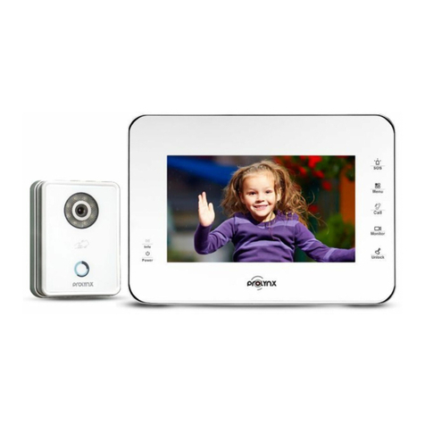
PROLYNX PL-VDIO06K Reference manual

PL-VDIO06K
Video Intercom System
INTRODUCTION MANUAL
Environmental Protection
of
facility to recycle, then recycle it.
For recycling proposal, please consult with the relevant
functional departments of local government, or retailers.
in

LIMITATION OF LIABILITY
This users' manual is supplied 'as is', with no warranties, be it expressed or implied, including,
but not limited to, the implied warranties of merchantability, suitability for any exact purpose, or
non-infringement of any third party's rights.
This publication may include technical inaccuracies or typos. The manufacturer holds the right
to introduce any changes to the information contained herein, for any purpose, including but not
limited to, improvements of the publications and/or related to the product, at any time, without
prior notice.
※
※
DISCLAIMER OF WARRANTY
The supplier shall not be liable to any party or any person, except for replacement or reasonable
maintenance of this product, for the cases, included but not limited to the following:
Any damage or loss, including but not limited to: direct/indirect, consequential, special, exemplary,
arising out of or related to the product;
Inappropriate use or negligence of the user in operation of the product, resulting in personal injury
or any damage;
Unauthorized disassembly, repair or modification of the product by the user;
Any problems or consequential inconvenience, loss or damage, caused by connecting this product
to devices of the third parties;
Any claim or action for damages, brought by any photogenic subject, be it a person or organization,
due to violation of privacy whereby the pictures taken by the device and/or saved data become
public or are used for the purposes other than intended.
※
※
※
※
※
SAFETY INSTRUCTIONS
1 2
Read these instructions and keep them in a safe place for future reference.
Please refer all work related to the installation of this product to qualified service personnel or
system technician.
Do not operate the appliance beyond its specified temperature, humidity or power source
ratings.
Securely install the devices on vertical surfaces (solid walls/doors) not prone to vibration or
impact.
Install the devices away from heat sources such as radiators, heat registers and stoves.
Installation of the terminal near consumer electronics devices, e.g. stereo receiver/amplifiers
and televisions, is permitted as long as the air surrounding the terminal does not exceed the
above mentioned temperature range.
Handle the appliance with care. Do not strike or shake, as this may damage the device.
The doorbell/camera units should be fitted with an approved weather shield if the chosen position
is in direct sunlight, or in contact with rain, snow or irrigation sprinkler systems.
Do not use strong or abrasive detergents when cleaning the appliance body. When the dirt is
hard to remove, use a mild detergent and wipe gently.
Do not overload outlets and extension cords as this may result in a risk of fire or electric shock.
Distributing, copying, disassembling, reverse compiling, reverse engineering, and also exporting
in violation of export laws of the software provided with this product, is expressly prohibited.
※
※
※
※
※
※
※
※
※
CARING FOR THE ENVIRONMENT BY RECYCLING
When you see this symbol on a product, do not dispose of the product with residential
or commercial waste.
Recycling your electrical equipment
Please do not dispose of this product with your residential or commercial waste. Some countries or
regions, such as the European Union, have set up systems to collect and recycle electrical and electronic
waste items. Contact your local authorities for information about practices established for your region.
COPYRIGHT STATEMENT
All rights reserved. No part of this publication may be reproduced in any form or by any means,
transcribed, translated into any language or computer language, transformed in any other way,
stored in a retrieval system, or transmitted in any form or by any means, electronic, mechanical,
recording, photocopying or otherwise, without the prior written permission of the owner.

Specification
Accessories
Indoor unit
Indoor unit ------------------------------------------------------------- 1pcs
Plastic Anchors -------------------------------------------------------- 4pcs
Screws ------------------------------------------------------------------- 4pcs
Bracket ------------------------------------------------------------------ 1pcs
4 Pin line --------------------------------------------------------------- 4pcs
If the indoor unit includes the internal power supply ,there is no external power
supply switch of the picture on the above.
User manual ------------------------------------------------------------ 1pcs
External power supply switch(Optional) ----------------------------- 1pcs
Install the indoor unit
Note:
Please be far from the intense radiation: TV, DVR, etc.devices with
Do not disassemble privately to avoid the electric shock.
Do not drop, shake or knock the device, otherwise will damage the elements.
Choose the best position to install, the horizontal view is 150cm.
Please power down before installation.
Keep at a distance of more than 30cm with AC power to avoid interference.
Away from the water, magnetic field and chemicals.
How to install the indoor unit
(Optional)
plastic anchors stent
cables
118.5mm
169mm
Monitoring
Talk
unlock
Hang up
Hang up
unlock
Talk
Monito ring
Monitoring
Talk
unlock
Hang up
20.4mm
Display
Resolution
Conversation duration
Standby status
Power supply
Operation temp.
Installation
Intercom mode
Working status
Surface mount
120 seconds
Video system PAL/NTSC compatible
4 inch TFT LCD
320(H)*3(RGB)*240(V)
50mA max.
Semi-Duplex communication
400mA max
118.5*169*20.4mm
Dimensions
External switching power
supply(DC 12V/1A)--optional
Built-in power supply
(AC 100V~240V)--optional
3 4

56
WIRING DIAGRAM
If you are using only one outdoor camera, you must connect it to the socket marked as CN1. If the
only outdoor camera is connected to the CN2 socket, the indoor unit will display a blank screen
when you attempt to activate monitoring mode to the 1st outdoor camera by pressing the button .
Please note that the part marked by the broken line will be annulled if you are using the indoor
unit which is internal switching power supply. Therefore you can directly connect the AC plug to AC
power supply.
The both of terminals(marked as CN1 CN2)is defined functionality as below:
1. DC12V 2. Audio 3. GND 4. Video
If you are using two outdoor cameras (for example, at the front door and the back gate), you
must use the CN1 CN2 . The two wires for connecting to the outdoor units are shown
in picture as below.
and sockets
Please be aware that up to 4 indoor monitors can be connected with 2
outdoor cameras.
Please note that the external switching power will be annulled if you are using the indoor unit
which is internal switching power supply. Therefore you can directly connect the AC plug to AC
power supply.
The both of terminals(marked as CN3 and CN4 ) is defined functionality as below:
A. Audio B. GND C. Data D. Video
MONITOR
OUTDOOR
CAMERA 1 CN1
C
N
2
CN3
CN4
1
2
3
4
DC12V
Audio
GND
Video
AC/DC
power
adapter
for
unlocking
(not
included)
AC/DC
electric
lock
(not
included)
Dry
contact
4321
AC100V~240V
External switching power supply
Video
GND
External camera
CN5
C
N
2
DC12V
Audio
GND
Video
AC/DC power
adapter
for unlocking
(not included)
AC/DC
electric lock
432 1
(not included)
GND
Camera
DC12V
Video
Select one
OUTDOOR
CAMERA 2
GND
C
N
2
MONITOR
OUTDOOR
CAMERA 1
CN1
CN3
1
2
3
4
DC12V
Audio
GND
Video
AC/DC
power
adapter
for
unlocking
(not
included)
AC/DC
electric
lock
(not
included)
Dry
contact
4321
AC100V~240V
External switching power supply
Video
GND
External camera
CN5
OUTDOOR
CAMERA 2
DC12V
Audio
GND
Video
AC/DC power
adapter
for unlocking
(not included)
AC/DC
electric lock
432 1
A
B
C
D
CN3 A
B
C
J1
CN1
(not included)
CN4 DA
B
C
D
C
N
2
External switching power supply
CN5
To next extention unit C 3
N
AC100v-240V
Extention Monitor
GND
Camera
DC12V
Video
Select one
GND
N
C2CN4
J1

78
NOTE ON WIRING CONNECTION
Please be aware of the internal switching power supply is applied to a wide range of AC
power (AC100~240V). Please first pull the AC power plug (shown as below)out before
installation of device.
Please note the silk printing marked on PCB in order to avoid incorrect connecting.
The wiring connection :requirement
1. 4C ordinary non-STP wiring cable,
Transmission ≤28m (4x0.2mm )
2. rom the outdoor camera to furthest indoor monitor:Effective distance f
Transmission ≤50m (4x0.3mm )
Transmission ≤80m (4x0.5mm )
2
2
2
The lock is not included in the package, you can purchase an electric lock which is suitable for
your need.
In the standard delivery the system supports locks with Normally Open (N.O.) door unlocking
method. It means that in the normal state the dry contact(page5) is opened so the lock is
kept under constant closed state. If the unlocking push-button is pressed and the dry contact
is changed to closed, then the lock is released.
The indoor monitor can be set up as main monitor and extension monitor on menu interface.
User can connect the both of 2 outdoor units to the main monitor, the socket marked as CN1
is to outdoor camera 1 and CN2 is to outdoor camera 2. The connection of other extension
monitors is in serial one by one, and the auxiliary connection of last extension monitor(near
main monitor) is direct to main monitor(the socket marked as C 4).
Please check that the socket of power supply(silk printing J1)is correct if you connect the
external switching power supply, otherwise it will damage the device.
Video
GND
CN5
External display
Video
GND
External camera
CN5
C 1
C 2
N
NC 4N
Wiring connection according to the following to avoid interference
Power+ Video
Audio GND GND Audio
Power+ Video
Please note that the camera connected to CN2 is used to watch the image around the door
if the camera of outdoor unit is masked. The CN2 can be only connected one device, so
you have to select one from outdoor unit 2 and camera.
Be aware that the electric current of camera 300mA max.
In addition it also supports connection of one external camera, if you want to get a more clear
image and you can also connect on external display. For detailed connections(socket C 1)
please follow the picture as below:
N
N
INDOOR MONITOR
TFT display View visitor’s image displayed on the TFT screen.
Microphone Transmit the voice to outdoor camera.
Unlock the door lock by pressing this button
1. Press the button to adjust the volume for the indoor device during
intercom.
2. In monitoring or talking mode, press the button to capture a frame
of the current video stream as a still photo.
3. In standby mode, press the button to view the pictures stored in the
built-in storage of the indoor device.
Allow user to observe the camera view at entrance in real
time.
image of
Name Descriptions
9
1. When the indoor device is in monitoring mode or some visitor press
the call button on the outdoor camera, press the button to
start
conversation with outdoor camera.
2. During conversation, press the button to transfer call to other
extension monitor.
3. In standby mode, press the button to start internal communication
among indoor units.
End conversation mode by pressing the button and the indoor unit will
go into standby mode.
Speaker Sound from outdoor camera.
Setting button, user can press the button, scroll the button upwards or
downwards.
Monitoring
Talk
unlock
Hang up
1
2
5
6
4
3
7
8
9
Monitoring
Talk
unlock
Hang up
Setting button
When the LCD screen is highlighted, press the button to bring up the menu interface as below to
set up the brightness, chroma and contrast of the LCD monitor. On menus, press the button to
select menu options, and scroll the button upwards or downwards to increase or decrease values.
By default, the values of the brightness, contrast and chroma are all set at 25, and the range of the
values can be set from 0 to 50. Select “Exit” and scroll the button to exit current menu.
Brightness 025
Contrast 025
Chroma 025
Exit

910
Menu Operation
Notice:
1. If users don’t do any operate or enter any interface about the indoor machine except
watching CCTV camera channel, the indoor device will be into standby mode after 1 minute
automatically.
2. A dark red background on the option indicates that the option has been selected, when
an option is in edit mode, the parameter of the option will be flashing.
In standby mode, press the button “ ” to access the menu interface, shows the menu
interface as shown below. On menu settings, press the button “ ” to move the cursor to
select menu options, and scroll the button “ ” to adjust values of each option, then press
“ ” to confirm. When select option “Exit”, scroll the button “ ” to exit menu interface, and
the indoor unit will be into standby mode. Or on menus, press the button “ ” to exit
menu interface.
Date 2015-02-06
Time 12:10:32
Ring1 08 08
Ring2 08 08
Delete All
8
1
2
Mode Master
Door2 Enable
Cam Enable
Unlock 10s
Exit
Hang up
[Date]: In this field, to adjust system date.
[Time]: In this field, to adjust system time.
[Ring1]: In this field, to adjust
[Mode]:
[Door2]: Enable or disable the preview of door2.
[Cam]: Enable or disable the preview of camera.
the doorbell tone of the outdoor camera 1, a total of 16, and the
ring volume can be set up from 01 to 08.
[Ring2]: In this field, to adjust the doorbell tone of the outdoor camera 2, a total of 16, and the
ring volume can be set up from 01 to 08.
[Delete All]: This option is to delete photos stored on the device. When the background of
this option is dark red, press “ ” by 3 seconds, it will bring a window as below, scroll “ ” upwards
or downwards to move the cursor, press “ ” to confirm, choose “No” to cancel, and choose “Yes”
it will delete all the photos stored on the machine.
Options include “Master” and “Slave”. “Master” indicates that the indoor unit connects
the outdoors or cameras, “Slave” indicates that the indoor unit connects the main or sub indoor
unit.
No
Yes
[Unlock]:
[Exit]: To exit current menu.
From this field, user can adjust unlock time for visitor calling, and values can be set
from 02s to 10s. For example, to select 5s, when visitor calling on the outdoor camera, if the
master release the door lock, visitor can go to the indoor unit within 5s, otherwise the
door lock will be switched off automatically after 5s.
Monitoring
OPERATION INTRODUCTION
VISITOR CALL
The Visitor press
the call button on
outdoor camera 1
A 10s of continuous
Ding Dong tone is heard
inside and outside
The visitor’s image
automatically displayed on
the screen
release the
door lock
Standby mode
Press the unlock
button on indoor
monitor
Press the Hang up
button on indoor
monitor
End
The Visitor press
the call button on
outdoor camera 2
If both call button on two outdoor camera are pressed at approximate
to the same time, the preference will be given to the outdoor camera
which call button was pressed first, unless the call button is pressed
again after the indoor monitor go into standby mode, please be aware
of that there is no indication on second outdoor camera but third
brief of tone will be heard on indoor monitor.
NOTICE:
Both the visitor s voice and image will be not switched off within 20s of time span when the
unlock button is pressed, this individualized function allow you to make sure whether the
visitor already come in.
Start conversation
with outdoor camera
Press the talk
button
The indoor unit will automatically go into standby mode if you are not
at home or have not reached the indoor unit in 60s.
The conversation
duration is 120s
at a time
Stop ringing
NOTICE:
Please be aware of Connection of 2 outdoor cameras is required.
◆
If the camera of outdoor unit is
masked, and can tsee the image.
Press this button to watch the image
from camera. Press it again to back
to the image of outdoor
unit.
’
Talk
unlock
Hang up
If a visitor press the call button on the outdoor camera, the first picture will be captured in
the built-in storage of the indoor unit.

11 12
If a conversation with outdoor unit is underway in monitoring mode,
press the call button on either of outdoor unit, the monitoring mode will be switched off. the
just visitor’s image will appear on its screen and continuous ringing will be heard. you can
press the talk button to reactivate conversation with the visitor ;for more detailed operations,
please refer to VISITOR CALL on page 10.
during this time a visitor
MONITORING
Standby mode
Please note that if you are using two outdoor cameras, but it appears a blank when
you are activating the monitoring mode on either of indoor units, to completely solve this
accident, please pull out all power supply of indoor unit and then plug in power supply back
after 10s later.
display
If you are using two indoor unit, you can also activate monitoring mode on other indoor unit,
the same image will be displayed on the screen respectively. Displaying which image on the
screen depends on which outdoor unit is being activated from indoor unit or which the
monitoring button is pressed last.
NOTICE:
If you are using only one outdoor camera in monitoring mode, you can also end the
monitoring mode by pressing the monitoring button again.
Please be aware of Connection of 2 outdoor cameras to 1 indoor monitor is required for d
entrance monitoring at least.
ual
◆
Press the call button
Call Outdoor
Press the hang
up button to end
the call.
DOOR2
Show DOOR2
image
DOOR1
Show DOOR1
image
CAM1
Show CAM1
image
Standby
Close LCD
Each monitoring time is 60S
Press the unlock
button on the
indoor unit, the
electric lock will be opened.
Monitoring Monitoring Monitoring
Talk
unlock
Hang up
Monitoring
CALL TRANSFER TO OTHER EXTENSION
Long-press this button to
access C
to other extension
all transfer
Start conversation
with outdoor camera
When you are transferring a call to other extension, the
original conversation indoor unit will return to standby
mode, and the indoor unit which the call is being
transferred will also sound a continuous Ding Dong tone
and the video image will appear on its screen.
A continuous Ding
Dong tone is heard
To release door lock, end conversation; please page 10 as reference. refer to
NOTICE:
Press t
on any of indoor units
he talk button
Outdoor camera call indoor
monitor and conversation
is underway
NOTICE:
INTERNAL COMMUNICATION AMONG INDOOR UNIT
Press t
button on any of
indoor units
he talk
Start conversation
among indoor units
Standby mode
Press the talk
button
A continuous Ding
Dong tone is heard
Press t
button
he Hang up End
NOTICE:
In mode, if a visitor press the call
button on either of outdoor unit, the internal communication
mode will be switched off. the just visitor’s image will appear
on its screen and continuous ringing will be heard. you can
press the talking button to reactivate
visitor; for more detailed operations, please refer to VISITOR
CALL on page 10.
internal communication
conversation with the
◆
At least 2 indoor units is required
At least 2 indoor units is required
◆
Talk
Talk
Talk
Talk
Hang up

13
How t o p laybac k
In standby mode, press the button “ ” to view the snapshot stored in the device, and scroll the
button “ ” upwards or downwards to the last file or the next file. Scroll the button “ ” upwards
or downwards and don’t loosen to turn pages quickly. During viewing the snapshot, press the
button “ ”, a flashing icon “ ” will appear on the screen, press the button “ ” to confirm to
delete the current picture. If user wants to delete all the pictures stored in the device, please refer
to the section “Menu Operation” on page 9. During viewing the snapshot, press the button “ ” or
“ ”, the device will go into standby mode.
2015/01/11 1 6:02:47
01/27 U nview 0 1
2015/01/11 1 6:02:47
01/27 U nview 0 1
How t o s naps hot
If a visitor press the call button on any outdoor camera, the first picture will be captured
automatically into the built-in storage of the indoor device.
In monitoring or talking mode, press the button “ ” to capture a frame of the current video stream
as a still photo.
The pictures stored in the built-in storage of the indoor device can be up to 250. If the number
of the pictures is up to 250, new snapshots will overwrite the previous images from the first picture
one by one.
Hang up
Other PROLYNX Intercom System manuals
Popular Intercom System manuals by other brands
Ekinex
Ekinex DICO EK-5DP-VI Administrator's guide
CyberData
CyberData 011214 Installation quick reference
D3D
D3D BELL Quick installation guide

Baldwin Boxall
Baldwin Boxall VIGIL AssureCare product manual

urmet domus
urmet domus iPercom elekta steel 1060/23 user manual
Vimar
Vimar ELVOX 8000 Series instruction sheet
urmet domus
urmet domus 1722 user guide

VIS-A-VIS
VIS-A-VIS VITALINQ 94A-07 Introduction and Training Module
Radio Active Designs
Radio Active Designs UV-1G user manual
Vimar
Vimar ELVOX Due Fili Plus K40505G.01 Installer manual
Entrotec
Entrotec PRO-DPC Installation and setup guide
Akuvox
Akuvox R26 user manual


