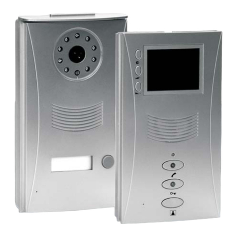
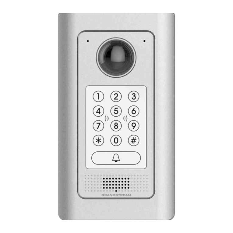
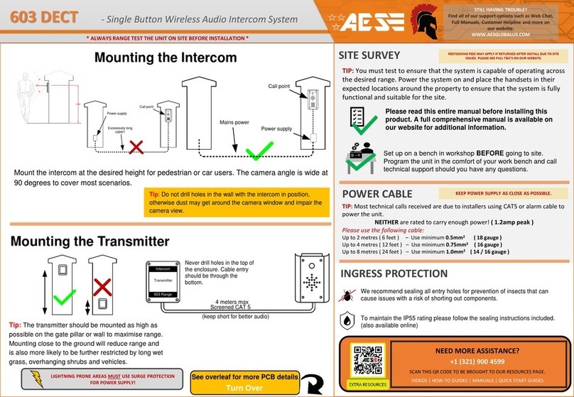
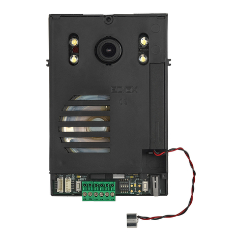
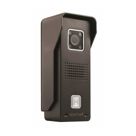
Entrotec PRO-DPC Assembly instructions

•BS 7671
•The Electricity at Work Regulations 1989
•ANSI/TIA-568.0-D
•ANSI/TIA-568.1-D
WARNING - ISOLATION OF ELECTRICAL EQUIPMENT
The Electricity at Work Regulations 1989,
01506 886 235 -
technicalsupport@entrotec.co.uk

Contents
1Cable Specification ............................................................................................................4
......................................................................................................
2Overview...........................................................................................................................5
.........................................................................................................................
3Connections ......................................................................................................................6
4Factory Default Settings.....................................................................................................7
5Assign an IP address ..........................................................................................................7
6Initialise ............................................................................................................................8
................................................................
7Login to Call Panel ...........................................................................................................10
8Provision.........................................................................................................................11
..........................................
...............................................
.......
9Configure ........................................................................................................................15
...................................................................................................................
..............................................................................................
.........................................................................................................
................................................................................................................
10 Apartment Station Configuration.....................................................................................17
................................................................................................................
................................................................................................
.........................................................................................................................
.......................................................................................................................
.......................................................................................................................
11 Device Registration..........................................................................................................21
................................................................................................................
............................................................................................................
..................................................................................................................

1
Category 5e Category 6
annealed pure copper
Connection
Cable
A
B
C
D
Typical Configuration
FIGURE 1-1
NOTE

2
Call Panel
2.1.1
FIGURE 2-1
2.1.2
FIGURE 2-2
A
B
C
D
E
F
G
A
B
C
D
E
F
G

3
FIGURE 3-1
Connection
Cable Type
Detail
FIGURE 3-2
A
B
C

4
Setting
Default
IP Address
Subnet
Gateway
Device Admin Code
Block No.
Door No.
5
5.1.1
FIGURE 5-1
i.
FIGURE 5-2

ii. 2846
FIGURE 5-3
i.
ii.
iii. X
NOTE
6
NOTE
WITH WITHOUT
Connect to Web Service and Initialise Device
i.
ii.
iii.
FIGURE 6-1
This
cannot be changed

iv. Next
WARNING
secure password
v. Next
FIGURE 6-2

7
i.
ii.
iii.
iv.
•admin
•password setup during initialisation
FIGURE 7-1

8
NOTE ON ENTROTEC CONNECT SERVER
Provisioning Systems without an Entrotec Connect Server
8.1.1
NOTE
i.
ii. Network Settings
FIGURE 8-1

iv. SIP Server
FIGURE 8-2
v. Enable
vi. Sever TypeVTO
vii. IP AddressPort
viii. Save
NOTE
8.1.2
i.
ii. Local SettingsBasic
iii. Block Name
iv. Door No.
v. Confirm
FIGURE 8-3

Provisioning Systems with an Entrotec Connect Server
8.2.1
i.
ii. Network SettingsSIP Server
FIGURE 8-4
iii. Enable
iv. Sever TypeExpress\DSS
v. IP AddressPort
vi. Domain VDPSIP Server UsernameSIP Server Password
vii. Save
NOTE
8.2.2
SIP server
Alternate SIP
Alternate SIP Server
FIGURE 8-5
i. Alternate IP Addr.
ii. Alternate UsernameAlternate
Password
iii. Alternate Server
iv. Save

8.2.3
i.
ii. SettingsBasic
iii. Block Name
iv. Door No.
v. Confirm
FIGURE 8-6
Provisioning Systems with an Entrotec Connect Server Installed
Retrospectively
8.3.1
8.3.2

9
Block Name
i.
ii. Local SettingsBasic
iii. Block Name
iv.
FIGURE 9-1
Video and Audio Settings
i.
ii. Local SettingsVideo & Audio
iii.
FIGURE 9-2
NOTE

Lock Release Time
i.
ii. Local SettingsAccess ControlLocal.
iii. Unlock Retry IntervalUnlock Time
iv.
FIGURE 9-3
v. Local SettingsAccess ControlRS485
vi. Unlock Response IntervalUnlock Time
vii. Save
FIGURE 9-4
Coded Access
i.
II. Local SettingsAccess ControlLocal.
iii. Public Unlock Password
iv. Enable
v.
FIGURE 9-5

10
Required Info
Factory Default Settings
Setting
Default
IP Address
Subnet
Gateway
Device User Passcode
Flat No.
Initialise
10.3.1
i.
FIGURE 10-1
ii. Password
WARNING
ecure password
iii. Emailsupport@entrotec.co.uk
FIGURE 10-2
iv. OK

10.3.2
i. Settings
FIGURE 10-3
ii. Password Verification
iii. OK.
FIGURE 10-4
iv. NetworkIP AddressSubnet Mask
Gateway
v. OK
FIGURE 10-5

Provision
10.4.1
i. User Config
ii. Flat No.
a. WITHOUTFlat No.
b. WITH Flat No. followed by #0
NOTE
FIGURE 10-6
iii. OK
iv. SIP Server
FIGURE 10-7
v.
a. WITHOUTServer IP Network Port
b. WITHServer IP Network Port
NOTE
vi. Domain User NameLogin Pwd
vii. OK

10.4.2
i. Door Config
ii.
FIGURE 10-8
NOTE
iii. EnableOFFON
iv. Enable ON OFF, ON
Configure
10.5.1
i. Settings
FIGURE 10-9
v. Password Verification
vi. OK.
Table of contents
Other Entrotec Intercom System manuals
Popular Intercom System manuals by other brands
golmar
golmar Tekna Uno Series Installation annex

Racing Electronics
Racing Electronics RT605 Installation operation & maintenance

Home Protector
Home Protector 61859 user guide
C-TEC
C-TEC PDA103i installation instructions
Contacta
Contacta STS-K080-IP Installation & user guide
Bticino
Bticino 365411 installation manual


