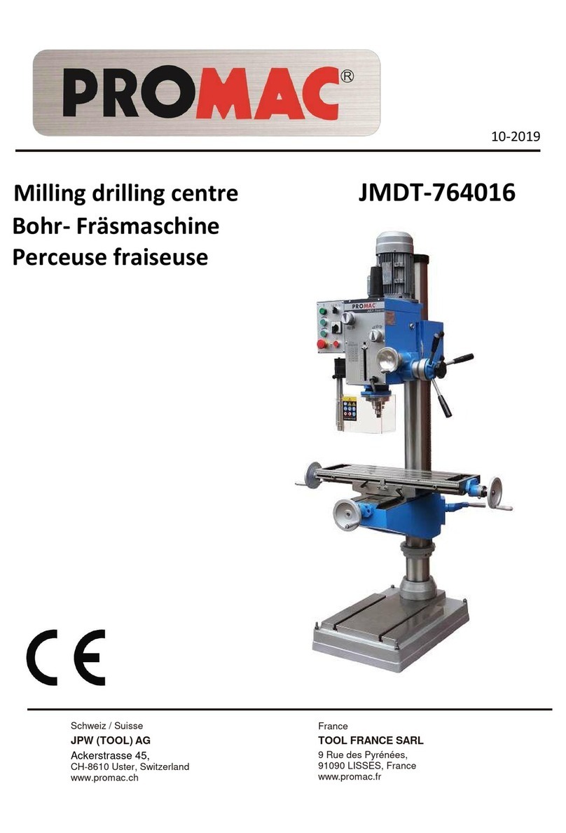
Promac JMDT-804516X-DRO User manual

CE-Conformity Declaration
CE-Konformitätserklärung
Déclaration de Conformité CE
Product / Produkt / Produit:
Milling Drilling Machine / Bohr- und Fräsmaschine / Fraiseuse Perceuse
JMDT-804516X-DRO
Brand / Marke / Marque:
PROMAC
Manufacturer or authorized representative / Hersteller
oder Bevollmächtigter / Fabricant ou son mandataire:
TOOL FRANCE S.A.S, 9 Rue des Pyrénées, 91090 LISSES, France
We hereby declare that this product complies with the regulations
Wir erklären hiermit, dass dieses Produkt der folgenden Richtlinie entspricht
Par la présente, nous déclarons que ce produit correspond aux directives suivantes
2006/42/EC
Machinery Directive / Maschinenrichtlinie / Directive Machines
2014/30/EU
electromagnetic compatibility
elektromagnetische Verträglichkeit
compatibilité électromagnétique
designed in consideration of the standards
und entsprechend folgender zusätzlicher Normen entwickelt wurde
et été développé dans le respect des normes complémentaires suivantes
EN ISO 12100:2010, EN 60204-1:2006+AC:2010, EN ISO 13128:2001+A2:2009/AC:2010,
EN 61000-6-4:2007+A1:2011, EN 61000-6-2:2005
Responsible for the Documentation / Dokumentations-Verantwortung / Résponsabilité de Documentation:
Head Product-Mgmt. / Leiter Produkt-Mgmt. / Resp. Gestion des Produits
TOOL FRANCE S.A.S
2019-09-01 Christophe SAINT SULPICE, General Manager
TOOL FRANCE S.A.S, 9 Rue des Pyrénées, 91090 LISSES, France

UKDeclaration of Conformity
Product
:
VARIABLE SPEED VERTICAL BAND SAW
Model:
JMDT-804516X-DRO
Brand:
PROMAC
AuthorizedRepresentative
:
TOOL FRANCE
S.A.S
Unit 1a Stepnell Park
Off Lawford Road
Rugby
CV21 2UX
United Kingdom
Weherebydeclarethatthisproductcomplieswiththe
regulations:
Supply of Machinery (Safety) Regulations 2008
Electromagnetic Compatibility Regulations 2016
designedinconsiderationofthe
standards:
EN ISO 12100:2010
EN 60204-1:2006+AC:2010
EN 13128:2001+A2:2009/AC:2010
EN 61000-6-4:2007+A1:2011
EN 61000-6-2:2005
ResponsiblefortheDocumentation
:
TOOL FRANCE
S.A.S
2021‐03‐26ChristopheSA INTSULPICE,General
Manager
TOOL FRANCE
S.A.S
9RuedesPyrénées,91090LISSES,
France

GB - ENGLISH
Operating Instructions
Dear Customer,
Many thanks for the confidence you have shown in us with the purchase of your new PROMAC-machine. This manual has been
prepared for the owner and operators of a JMDT-804516X milling drilling center to promote safety during installation, operation
and maintenance procedures. Please read and understand the information contained in these operating instructions and the
accompanying documents. To obtain maximum life and efficiency from your machine, and to use the machine safely, read this
manual thoroughly and follow instructions carefully.
…Table of Contents
1. Declaration of conformity
2. PROMAC Warranty
3. Safety
Authorized use
General safety notes
Remaining hazards
4. Machine specifications
Technical data
Noise emission
Contents of delivery
5. Transport and start up
Transport and installation
Assembly
Mains connection
Initial lubrication
Starting operation
6. Machine operation
Controls
Spindle speed selection
7. Setup and adjustments
Changing spindle speeds
Arbor replacement
Adjusting the depth stop
Engaging the fine feed wheel
Return spring adjustment
Before operation
After operation
Adjustment of head
Preparing for drilling
Preparing for milling
8. Maintenance and inspection
Weekly lubrication
Daily lubrication
Slide adjustments
Lead screw nut adjustment
9. Trouble shooting
10. Available accessories
1. Declaration of conformity
On our own responsibility we hereby
declare that this product complies with
the regulations listed on page 2.
Designed in consideration with the
standards.
2. PROMAC Warranty
TOOL FRANCE S.A.S guarantees that
the supplied product(s) is/are free from
material defects and manufacturing
faults.
This warranty does not cover any
defects which are caused, either directly
or indirectly, by incorrect use,
carelessness, damage due to accidents,
repairs or inadequate maintenance or
cleaning as well as normal wear and
tear.
Further details on warranty (e.g.
warranty period) can be found in the
General Terms and Conditions (GTC)
that are an integral part of the contract.
These GTC may be viewed on the
website of your dealer or sent to you
upon request.
TOOL FRANCE S.A.S reserves the
right to make changes to the product
and accessories at any time.
3. Safety
3.1 Authorized use
This milling drilling center is designed
for milling and drilling machinable metal
and plastic materials only. Machining of
other materials is not permitted and
may be carried out in specific cases
only after consulting with the
manufacturer.
Never cut magnesium-
high danger to fire!
The proper use also includes
compliance with the operating and
maintenance instructions given in this
manual.
The machine must be operated only by
persons familiar with its operation and
maintenance and who are familiar with
its hazards.
The required minimum age must be
observed.
The machine must only be used in a
technically perfect condition.
When working on the machine, all
safety mechanisms and covers must be
mounted.
In addition to the safety requirements
contained in these operating
instructions and your country’s
applicable regulations, you should
observe the generally recognized
technical rules concerning the operation
of metalworking machines.
Any other use exceeds authorization.
In the event of unauthorized use of the
machine, the manufacturer renounces
all liability and the responsibility is
transferred exclusively to the operator.
3.2 General safety notes
Metalworking machines can be
dangerous if not used properly.
Therefore the appropriate general
technical rules as well as the following
notes must be observed.
Read and understand the entire
instruction manual before attempting
assembly or operation.
Keep this operating instruction close by
the machine, protected from dirt and
humidity, and pass it over to the new
owner if you part with the tool.
No changes to the machine may be
made.
Daily inspect the function and existence
of the safety appliances before you start
the machine.
Do not attempt operation in this case,
protect the machine by unplugging the
power cord.

Remove all loose clothing and confine
long hair.
Before operating the machine, remove
tie, rings, watches, other jewellery, and
roll up sleeves above the elbows.
Wear safety shoes; never wear leisure
shoes or sandals.
Always wear the approved working
outfit.
Do not wear gloves.
Wear goggles when working
Install the machine so that there is
sufficient space for safe operation and
work piece handling.
Keep work area well lighted.
The machine is designed to operate in
closed rooms and must be bolted to the
cabinet stand or a solid work bench.
Make sure that the power cord does not
impede work and cause people to trip.
Keep the floor around the machine
clean and free of scrap material, oil and
grease.
Stay alert!
Give your work undivided attention. Use
common sense. Do not operate the
machine when you are tired.
Do not operate the machine under the
influence of drugs, alcohol or any
medication. Be aware that medication
can change your behaviour.
Never reach into the machine while it is
operating or running down.
Never leave a running machine
unattended. Before you leave the
workplace switch off the machine.
Keep children and visitors a safe
distance from the work area.
Do not operate the electric tool near
inflammable liquids or gases.
Observe the fire fighting and fire alert
options, for example the fire
extinguisher operation and place.
Do not use the machine in a dump
environment and do not expose it to
rain.
Work only with well sharpened tools.
Always close the chuck guard and
pulley cover before you start the
machine.
Remove the chuck key and wrenches
before machine operation.
Specifications regarding the maximum
or minimum size of the work piece must
be observed.
Do not remove chips and work piece
parts until the machine is at a standstill.
Do not stand on the machine.
Connection and repair work on the
electrical installation may be carried out
by a qualified electrician only.
Have a damaged or worn power cord
replaced immediately.
Never place your fingers in a position
where they could contact any rotating
tool, chuck or cutting chips.
Secure workpiece against rotation. Use
fixtures, clamps or a vice to hold the
workpiece.
Never hold the workpiece with your
hands alone.
When using a vice, always fasten it to
the table.
Never do any works “freehand” (hand-
holding the work piece rather than
supporting it).
Never move the head while the machine
is running.
If a work piece overhangs the table
such that it will fall or tip if not held,
clamp it to the table or provide auxiliary
support.
Check the save clamping of the work
piece before starting the machine.
Remove cutting chips with the aid of an
appropriate chip hook when the
machine is at a standstill only.
Never stop the rotating chuck or tool
with your hands.
Measurements and adjustments may be
carried out when the machine is at a
standstill only.
Setup work may only be carried out
after the machine is protected against
accidental starting by pressing the
emergency stop button.
Maintenance and repair work may only
be carried out after the machine is
protected against accidental starting by
pulling the mains plug.
Do not use wire wheels or grinding
wheels on this machine.
To avoid injury from parts thrown by the
spring, follow instructions exactly as
given when adjusting the spring tension
of the quill (see chapter 7.5)
3.3 Remaining hazards
When using the machine according to
regulations some remaining hazards
may still exist.
The rotating chuck, tool and cutting
chips can cause injury.
Thrown and hot work pieces and cutting
chips can lead to injury.
Chips, dust and noise can be health
hazards. Be sure to wear personal
protection gear such as safety goggles,
dust mask and ear protection.
The use of incorrect mains supply or a
damaged power cord can lead to
injuries caused by electricity.
4. Machine specifications
4.1 Technical data
JMDT-804516X-DRO:
Drilling capacity(Iron/Steel) 45/45*mm
Milling capacity of face mill 80mm
Milling capacity of end mill 32mm
Tapping capacity(Iron/Steel)16/16*mm
(*not for intense operations) 32mm
Spindle to column 260mm
Distance table to spindle max 460mm
Spindle taper MT-4
Draw bar M16
Spindle travel 120mm
Spindle speeds…75-435/435-2500rpm
Max travel X-axis 560mm
Max travel Y-axis 190mm
Table size 240x800mm
T-slots...3 14mm
Overall (LxWxH) 1280x960x2080mm
Net weight 486kg
Mains 3~400V, PE, 50Hz
Output power 1,5 kW S1
Reference current 3.7A
Extension cord (H05VV-F): 4Gx1,5²
Installation protection 4-6.3A
4.2 Noise emission
Acoustic pressure level (EN 11202):
Idling at maximum speed 85 dB (A)
The specified values are emission levels
and are not necessarily to be seen as
safe operating levels.
As workplace conditions vary, this
information is intended to allow the user
to make a better estimation of the
hazards and risks involved only.
4.3 Content of delivery
1-13mm drill chuck with arbour MT4
Draw bar M16
Head rising crank and handle
3 Table handwheels
Operating tools
Operating manual
Spare parts list.
5. Transport and start up
5.1 Transport and installation
The machine will be delivered in a
closed crate.
For transport use a forklift or hand
trolley. Make sure the machine does not
tip or fall off during transport.
The machine is designed to operate in
closed rooms and must be bolted to the
cabinet stand or a solid work bench.
For packing reasons the machine is not
completely assembled.
5.2 Assembly
If you notice transport damage while
unpacking, notify your supplier
immediately. Do not operate the
machine!
Dispose of the packing in an
environmentally friendly manner.
Clean all rust protected surfaces with
petroleum, diesel oil or a mild solvent.
Screw rubber handles onto quill down
feed handle rods (A, Fig 1). Screw
handle rods into hub and tighten.
Slide handwheels (B) onto table
handwheel shafts and tighten set
screws.
Install handle (C)
Mounting machine to stand or solid
workbench.
Unbolt the machine from the shipping
crate bottom.
Caution:
The machine is heavy.
JMDT-804516X-DRO= 486 kg!
Assure the sufficient load capacity
and proper condition of your lifting
devices.
Never step underneath suspended
loads.
Carefully place the machine onto the
cabinet stand or a solid work bench.
Use a machinist’s precision level to
make sure that the machine table is
level.
Loosen mounting bolts, shim and
tighten mounting bolts if needed.
The machine must be level to be
accurate.
5.3 Mains connection
Mains connection and any extension
cords used must comply with applicable
regulations.
The mains voltage must comply with the
information on the machine licence
plate.
The mains connection must have a
6-10A Circuit breaker.
Only use power cords
marked H05VV-F
Connections and repairs to the
electrical equipment may only be
carried out by qualified electricians.
Connection takes place on the
appropriate terminal in the electrical
cabinet on the left side of the machine.
5.4 Initial lubrication
The machine must be serviced at all
lubrication points before it is placed into
service!
Failure to comply may cause serious
damage.
(see chapter 8 for lubrication)
5.5 Starting operation
Before starting the machine check the
proper chucking (see chapter 6.2)
You can start the machine with the
green ON-button (K, Fig 4).
The red button on the control box stops
the machine (M).
The emergency stop button (L) stops all
machine functions.
Attention:
The machine still has electric power.
Turn emergency stop button clockwise
to reset.
The Forward/Reverse buttons (P/Q)
may only be operated when motor
power has been stopped before.
WARNING:
Do not change the spindle running
direction while machine is running.
Improper operation may damage the
Fw/Rev switch and gears.
6. Machine operation
Warning:
Setup work may only be carried out
after the machine is protected
against accidental starting.
With pressed emergency stop button.
Never place your fingers in a position
where they could contact any rotating
tool, chuck or cutting chips.
Remove cutting chips with the aid of an
appropriate chip hook when the
machine is at a standstill only.
Never stop the rotating chuck or tool
with your hands.
Always close the chuck guard and
pulley cover before you start the
machine.
Secure workpiece to the table with
clamps or a vice to prevent rotating with
the drill bit.
When using a vice, always fasten it to
the table.
Check the save clamping of the
workpiece, chuck and tools before
starting the machine.
Never do any works “freehand” (hand-
holding the work piece rather than
supporting it on the table).
Support long workpieces with helping
roller stands.
Always adjust the depth stop to prevent
drilling into the table or into the
worholding device.
Feed a drill bit into the material with
only enough force to allow the drill bit to
work. Feeding too slowly may cause
burning of the workpiece or tool.
Feeding too quickly may cause the
motor to stop and/or the drill bit to break.
Do not use wire wheels or grinding
wheels on this machine.
Never cut magnesium-
high danger to fire!
Fig 1
6

Measurements and adjustments may be
carried out when the machine is at a
standstill only.
In case of danger push the
emergency stop button.
6.1 Controls
Fig 2
A….X-axis handwheel
A1 ….X-axis power feed
B….Y-axis handwheel
C….X-axis adjustable stop
D….X-axis slide lock
E….Y-axis slide lock
Fig 3
F….Drill depth stop adjustment knob
G….Downfeed handles
H…..Fine feed hand wheel
I…..Fine feed engagement knob
J….Fine feed dial
Fig 4
K….Power ON button / Power Light
L….Emergency stop button
M….Power OFF button
N….Quill lock handle
O….Drilling / Tapping Switch
P….Foward button
Q….Reverse button
R….Motor
S…. Speed control knob
T….Draw bar cover
U….Head tilting lock nuts
V….Z-axis slide lock
6.2 Spindle speeds selection
The correct spindle speed depends on
the type of machining, the cutting
diameter, the material to be machined
and the cutting tool.
These are recommended max. speeds
for a 10mm high speed steel (HSS) tool
(e.g. drill bit).
Aluminium, brass 1500 RPM
Cast iron 1000 RPM
Mild steel 800 RPM
High carbon steel 600 RPM
Stainless steel 300 RPM
If a carbide (HM) tool is used about 5
times higher speeds can be chosen.
Generally speaking, the larger in
relation the cutting diameter, the smaller
the possible RPM.
For example:
Milling mild steel with an end mill of
20mm allows a speed of
400 RPM max. with HSS tool
2000 RPM max. with carbide tool
7. Setup and adjustments
Warning:
Setup and adjustment work may only
be carried out after the machine is
protected against accidental starting.
Press emergency stop button!
7.1 Changing spindle speeds
Speeds may only be changed at
complete spindle standstill.
WARNING:
Changing speeds during spindle or
motor rotation will damage the gears.
Refer to the speed chart whenever
changing speeds.
7.2 Arbor replacement
Remove the draw bar cover (T, Fig 4).
Select the lowest spindle speed to keep
the spindle from turning.
Loosen the drawbar with a wrench.
Loosen the drawbar 2 to max 3 full turns.
Tap the drawbar head with a rubber
mallet to dislodge the tool taper.
7.3 Adjusting the Depth Stop
To drill multiple holes at the same
preset depth, use the depth stop:
Turn the knob of depth stop(F, Fig 3) to
move to the desired position.
7.4 Engaging the Fine Feed Wheel
To activate the fine feed hand wheel
tighten the engagement knob (I, Fig 3).
7.5 Return Spring Adjustment
The return spring is adjusted at the
factory and should not need further
adjustment. If adjustment is necessary:
Loosen knob (X, Fig. 5) approximately
6mm.
Do not remove the spring cover (Y).

Fig 5
Firmly hold the spring cover (Y).
Pull out the cover and rotate until the
pin (Z) on the return spring plate
engages the next notch in the coil
spring cover. Turn the cover clockwise
to decrease tension and counter-
clockwise to increase tension.
Tighten knob (X).
7.6 Before Operation
Prepare oil gun with coolant or cutting
oil.
In order to keep the accurate precision,
the table must be free form dust and oil
deposites.
Check to see that the tools are correctly
set and the workpiece is set firmly.
Be sure the speed is not set to fast.
Be sure everthing is ready before use
7.7 After Operation
Turn off the electric switch.
Turn down the tools.
Clean the machine and coat it with
lubricant.
Cover the machine with cloth to keep
out the dust.
7.8 Adjustment of Head
To raise and lower the head, loosen the
two nuts (V, Fig 6) located on the right
side of the Z-slide.
Fig 6
Use the crank (Fig 7) to raise and lower
the head.
When the desired height is reached
tighten the 2 nuts to avoid vibration.
Fig 7
The head may be rotated 360º around
the column.
Loosen the 2 nuts (V, Fig 6).
Adjust the head, then well tighten the
nuts to avoid movement under
machining loads.
Fig 8
The head may be tilted left/right.
Loosen 3 nuts (U, Fig 8).
Tilt the head to the degrees you wish on
the scale, then well tighten the 3 nuts to
avoid vibration.
7.9 Preparing for Drilling.
Loosen the quill lock (N, Fig 4, Fig 9).
Loosen the knob (I) to make loose the
taper clutch of worm gear, to disengage
the fine feed (H).
Set the positive depth stop (F) to the
desired drilling depth.
Fig 9
7.10 Preparing for Milling
Adjust the positive depth stop (F, Fig 9)
to highest point position.
Turn tight of the knob (I) to engage the
taper clutch, to engage the fine feed (H).
Turn the fine feed hand wheel (H) to
adjust the desired machining height.
Tighten the quill lock (N) to avoid
vibration.
8. Maintenance and inspection
General notes:
Maintenance, cleaning and repair
work may only be carried out after
the machine is protected against
accidental starting.
Push the emergency stop button and
disconnect from the power source!
Clean the machine regularly.
Defective safety devices must be
replaced immediately.
Repair and maintenance work on the
electrical system may only be carried
out by a qualified electrician.
8.1 Weekly Lubrication:
Weekly apply oil:
DIN 51502 CG ISO VG68
(e.g. BP Maccurat 68, Castrol Magna BD
68, Mobil Vectra 2)
- X-axis lead screw
Apply oil on entire length.
- Y-axis lead screw
Move the table forward and remove the
way cover for access.
Apply oil on entire length.
- Z-axis lead screw
Move the head up and remove the way
cover for access.
Apply oil on entire length.
8

8.2 Daily Lubrication:
Daily apply oil:
CGLP DIN 51502 ISO VG68
(e.g. BP Maccurat 68, Mobil Vectra 2)
- X/Y-axis hand wheels
Lubricate ball oilers.
- Z-axis crank handle
Lubricate ball oiler.
- X/Y-axis ways
Lubricate ways on entire length.
- Z-axis ways
Fill reservoir oiler.
- Spindle quill
Apply oil on entire length.
8.3 Slide adjustments
X-axis and Y-axis slides are fitted with
tapered gibs.
Fig 10
If adjustment is needed:
Tighten gib screw (A, B, Fig 10)
clockwise appr. a quarter turn.
Try and repeat until slide moves freely
without play.
8.4 Lead screw nut adjustment
The table is fitted with an adjustable
(slotted) leadscrew nut.
Tighten adjusting screw on leadscrew
nut to reduce the backlash.
9. Trouble shooting
Motor doesn’t start
*No electricity-
check mains and fuse.
*Defective switch, motor or cord-
consult an electrician.
Machine vibration
*Incorrect belt tension-
adjust belt tension.
*Stand on uneven floor-
adjust stand for even support.
*Tool deflection-
reduce tool length.
*Slide backlash-
adjust slide gibs.
*Slides running dry-
lubricate with oil.
*Dry spindle quill-
lubricate spindle quill.
*Dull tool tip-
resharpen or change tool.
*Chip load too high-
reduce depth of cut or feed-
*Table leadscrew nut has play-
tighten adjusting screw.
Tool tip burns
*Cutting speed too high-
reduce spindle speed.
*Dull tool tip-
resharpen tool tip.
Drill leads off
*cutting lips or angle not equal-
resharpen drill bit correctly.
*drilled hole off centre-
drill a pilot hole first.
*bent drill bit-
use a proper drill bit.
*drill bit not properly installed-
install drill bit correctly.
10. Environmental protection
Protect the environment.
Your appliance contains valuable
materials which can be recovered or
recycled. Please leave it at a
specialized institution.
This symbol indicates separate
collection for electrical and electronic
equipment required under the WEEE
Directive (Directive 2012/19/EC) and is
effective only within the European Union.
11. Available accessories
Refer to the PROMAC-Pricelist for
various accessories.

JMDT-804516X-DRO Headstock Assembly -1
10

JMDT-804516X-DRO Parts List for Headstock Assembly -1
Index Part
No. No. Description Size Qty.
1 ................ JMDT804516X-1001............head body ..................................................... 20010B..................................1
2 ................ JMDT804516X-1002............head body cover ........................................... 20011B..................................1
3 ................ JMDT804516X-1003............Int retaining ring ......................................... Φ62 GB/T893.1-1986 ...........2
4 ................ JMDT804516X-1004............Int retaining ring ........................................... Φ35 GB/T894.1-1986 ...........2
5 ................ JMDT804516X-1005............airtight base .................................................. 20018B..................................1
6 ................ JMDT804516X-1006............airtight ring ................................................... 45×35X10 GB/T9877.1-1988.....2
7 ................ JMDT804516X-1007............motor ............................................................ 1.5KW ...................................1
8 ................ JMDT804516X-1008............screw............................................................. M8X25 ..................................1
9 ................ JMDT804516X-1009............washer........................................................... 8 GB/T97.1-2002 ..................1
10 .............. JMDT804516X-1010............plate .............................................................. 20201....................................1
11 .............. JMDT804516X-1011............arbor bolt cover ............................................ 20304-1B ..............................1
12 .............. JMDT804516X-1012............arbor bolt cover base.................................... 20304V1................................1
13 .............. JMDT804516X-1013............screw............................................................. M8X45 GB/T70.1-2000 .........6
14 .............. JMDT804516X-1014............pin ................................................................. 8×40 GB/T118-2000 .............2
15 .............. JMDT804516X-1015............screw............................................................. M10×10 GB/T79-2000 ..........1
16 .............. JMDT804516X-1016............screw............................................................. M10×8 GB/T77-2000 ............1
17 .............. JMDT804516X-1017............key................................................................. 6X28 GB/T1096-2003 ...........1
18 .............. JMDT804516X-1018............bolt................................................................ ZG3/8” ..................................1
19 .............. JMDT804516X-1019............cap................................................................. 20020B..................................2
20 .............. JMDT804516X-1020............speed lever.................................................... 20307B..................................2
21 .............. JMDT804516X-1021............pin ................................................................. 3X18 GB/T879.2-2002 ..........2
22 .............. JMDT804516X-1022............oil plug .......................................................... ZG3/8” ..................................1
23 .............. JMDT804516X-1023............screw............................................................. M5x10...................................3
24 .............. JMDT804516X-1024............screw............................................................. M4X8 GB/T818-2000 ............6
25 .............. JMDT804516X-1025............oil pointer...................................................... M18X1.5 ...............................1
26 .............. JMDT804516X-1026............I shaft ............................................................ 20105B..................................1
27 .............. JMDT804516X-1027............Gear Z14....................................................... 20105-1-B .............................1
28 .............. JMDT804516X-1028............bearing.......................................................... 6003 / P5 GB/T276-1994 ......3
29 .............. JMDT804516X-1029............bearing.......................................................... 6007 / P5 GB/T276-1994 ......3
30 .............. JMDT804516X-1030............key................................................................. 5X25 GB/T1096-2003 ...........1
31 .............. JMDT804516X-1031............II shaft ........................................................... 20106V..................................1
32 .............. JMDT804516X-1032............Gear Z35....................................................... 20110V..................................1
33 .............. JMDT804516X-1033............Magnetic beads............................................. ..............................................4
34 .............. JMDT804516X-1034............spacer bush .................................................. 20304V..................................1
35 .............. JMDT804516X-1035............Gear Z41....................................................... 20106-1-B .............................1
36 .............. JMDT804516X-1036............bearing.......................................................... 6202 / P5 GB/T276-1994 ......4
37 .............. JMDT804516X-1037............key................................................................. 6X36......................................1
38 .............. JMDT804516X-1038............The probe holder .......................................... ..............................................1
39 .............. JMDT804516X-1039............ball ................................................................ ¢8 .......................................1
40 .............. JMDT804516X-1040............spring ............................................................ ..............................................1
41 .............. JMDT804516X-1041............Ext retaining ring........................................... ¢18 GB/T894.1-1986..........1
42 .............. JMDT804516X-1042............searching unit ............................................... ..............................................1
43 .............. JMDT804516X-1043............screw............................................................. M6X12 GB/T71-1985 ............2
44 .............. JMDT804516X-1044............III shaft .......................................................... 20107V..................................1
45 .............. JMDT804516X-1045............Gear Z18....................................................... 20110-2-B .............................1
46 .............. JMDT804516X-1046............spacer bush................................................... 20107V.1...............................1
47 .............. JMDT804516X-1047............Accused of head cover .................................. 20304V2................................1
48 .............. JMDT804516X-1048............Gear Z43....................................................... 20113-B ................................1
49 .............. JMDT804516X-1049............Gear Z16....................................................... 20115-B ................................1

JMDT-804516X-DRO Parts List for Headstock Assembly -1
Index Part
No. No. Description Size Qty.
50 .............. JMDT804516X-1050............key................................................................. 5X50 GB/T1096-2003 ...........1
51 .............. JMDT804516X-1051............key................................................................. 6X18 GB/T1096-2003 ...........1
52 .............. JMDT804516X-1052............key................................................................. 6X18 GB/T1096-2003 ...........1
53 .............. JMDT804516X-1053............spindle sleeve................................................ 20019....................................1
54 .............. JMDT804516X-1054............spindle........................................................... 20104B..................................1
55 .............. JMDT804516X-1055............bearing ......................................................... 30207 /P5 .............................1
56 .............. JMDT804516X-1056............bearing.......................................................... 30206 /P5 .............................1
57 .............. JMDT804516X-1057............splined sleeve Z25 ........................................ 20114V..................................1
58 .............. JMDT804516X-1058............Gear Z53...................................................... 20116-B ................................1
59 .............. JMDT804516X-1059............Ext retaining ring........................................... ¢35.....................................1
60 .............. JMDT804516X-1060............feed base....................................................... 20012....................................1
61 .............. JMDT804516X-1061............support base ................................................. 20128....................................1
62 .............. JMDT804516X-1062............nut................................................................. 20129....................................1
63 .............. JMDT804516X-1063............knob .............................................................. 20130....................................1
64 .............. JMDT804516X-1064............graduated rod ............................................... 20131....................................1
65 .............. JMDT804516X-1065............fixed bolt ....................................................... 20021....................................1
66 .............. JMDT804516X-1066............scale board.................................................... 20132....................................1
67 .............. JMDT804516X-1067............lock washer ................................................... ¢30.....................................1
68 .............. JMDT804516X-1068............lock nut ......................................................... M30X1.5 ...............................1
69 .............. JMDT804516X-1069............rubber washer............................................... 20308....................................1
70 .............. JMDT804516X-1070............screw............................................................. M4X8 ....................................1
71 .............. JMDT804516X-1071............split pin ......................................................... 3X18......................................1
72 .............. JMDT804516X-1072............bolt................................................................ M8X30 ..................................1
73 .............. JMDT804516X-1073............separating ring .............................................. 20024B..................................1
74 .............. JMDT804516X-1074............Bearing cover ................................................ 20133B..................................1
75 .............. JMDT804516X-1075............screw............................................................. M5X6 ....................................1
76 .............. JMDT804516X-1076............pin ................................................................. M5X4 ....................................1
77 .............. JMDT804516X-1077............worm wheel box ........................................... 20015....................................1
78 .............. JMDT804516X-1078............worm shaft.................................................... 20119....................................1
79 .............. JMDT804516X-1079............worm cover ................................................... 20302....................................1
80 .............. JMDT804516X-1080............screw............................................................. M6X12 GB/T77-2000 ............1
81 .............. JMDT804516X-1081............separating ring .............................................. 20120....................................1
82 .............. JMDT804516X-1082............worm wheel .................................................. 20016....................................1
83 .............. JMDT804516X-1083............pinion shaft ................................................... 20117....................................1
84 .............. JMDT804516X-1084............handle body .................................................. 20013....................................1
85 .............. JMDT804516X-1085............spring base.................................................... 20118....................................1
86 .............. JMDT804516X-1086............spring cap...................................................... 20123....................................1
87 .............. JMDT804516X-1087............spring plate ................................................... 20122....................................1
88 .............. JMDT804516X-1088............big ripple handle ........................................... 20303....................................1
89 .............. JMDT804516X-1089............compression spring....................................... ..............................................1
90 .............. JMDT804516X-1090............graduated plate ............................................ 20017....................................1
91 .............. JMDT804516X-1091............handle rod..................................................... 20121B..................................1
92 .............. JMDT804516X-1092............handle ball .................................................... 20301B..................................1
93 .............. JMDT804516X-1093............handle wheel................................................. 20306B..................................1
94 .............. JMDT804516X-1094............handle rod..................................................... 20305-B ................................1
95 .............. JMDT804516X-1095............screw............................................................. M8X25 GB/T70.1-2000 .........2
96 .............. JMDT804516X-1096............screw............................................................. 10107....................................1
97 .............. JMDT804516X-1097............washer........................................................... 203063..................................1
98 .............. JMDT804516X-1098............screw............................................................. 203066..................................1
99 .............. JMDT804516X-1099............screw............................................................. M6X12 GB/T818-2000 ..........3
12

JMDT-804516X-DRO Parts List for Headstock Assembly -1
Index Part
No. No. Description Size Qty.
100 ............ JMDT804516X-1100............screw............................................................. M5X12 GB/T70.1-2000 .........1
101 ............ JMDT804516X-1101............pin ................................................................. 3X12......................................2
102 ............ JMDT804516X-1102............key................................................................. 8X20......................................1
103 ............ JMDT804516X-1103............screw............................................................. M5X20 ..................................2
104 ............ JMDT804516X-1104............pin ................................................................. 3X15 GB/T879.2-2002 ..........1
105 ............ JMDT804516X-1105............fixed bolt ....................................................... 20124B..................................1
106 ............ JMDT804516X-1106............fixed tight block ............................................ 20203B..................................1
107 ............ JMDT804516X-1107............fixed tight block ............................................ 20202B..................................1
108 ............ JMDT804516X-1108............adjust handle ................................................ ..............................................1
109 ............ JMDT804516X-1109............lever shaft ..................................................... 20125B..................................1
110 ............ JMDT804516X-1110............lever .............................................................. 20022-1B ..............................1
111 ............ JMDT804516X-1111............lever bracket ................................................. 20204-2B ..............................1
112 ............ JMDT804516X-1112............Ext retaining ring........................................... 12 GB/T9877.1-1988 ............1
113 ............ JMDT804516X-1113............screw ............................................................ M6X16 GB/T70.1-2000.........1
114 ............ JMDT804516X-1114............screw............................................................. M4X16 ..................................3
115 ............ JMDT804516X-1115............oil seal ........................................................... 12X22X8 GB/T9877.1-1988 ..2
116 ............ JMDT804516X-1116............screw............................................................. M4X16 ..................................2
117 ............ JMDT804516X-1117............screw............................................................. M4X18 ..................................2
118 ............ JMDT804516X-1118............oil seal ........................................................... FB35X62X10 GB/T9877.1-1988.1

JMDT-804516X-DRO BASE PARTS -2
14

JMDT-804516X-DRO Parts List for BASE PARTS -2
Index Part
No. No. Description Size Qty.
1 ................ JMDT804516X-2001............Base............................................................... 10010....................................1
2 ................ JMDT804516X-2002............column .......................................................... 10013....................................1
3 ................ JMDT804516X-2003............square flange ................................................ 10021....................................1
4 ................ JMDT804516X-2004............raise and lower base ..................................... 10016....................................1
5 ................ JMDT804516X-2005............gib strip ......................................................... 10025....................................1
6 ................ JMDT804516X-2006............screw............................................................. 10106....................................6
7 ................ JMDT804516X-2007............bearing.......................................................... 51103 GB/T301-1995 ...........4
8 ................ JMDT804516X-2008............table screw.................................................... 10104....................................1
9 ................ JMDT804516X-2009............dial clutch...................................................... 10102....................................3
10 .............. JMDT804516X-2010............graduated plate ............................................ 10111....................................3
11 .............. JMDT804516X-2011............wheel ............................................................ 10301....................................3
12 .............. JMDT804516X-2012............turn handle ................................................... 20305-1B ..............................3
13 .............. JMDT804516X-2013............screw............................................................. 20305-1B ..............................3
14 .............. JMDT804516X-2014............nut................................................................. 10024....................................1
15 .............. JMDT804516X-2015............nut bracket.................................................... 10117....................................1
16 .............. JMDT804516X-2016............cover ............................................................. 10014....................................1
17 .............. JMDT804516X-2017............screw............................................................. M8X20 GB/T70.1-2000 .........3
18 .............. JMDT804516X-2018............screw............................................................. M8X25 GB/T70.1-2000 .........4
19 .............. JMDT804516X-2019............pin ................................................................ 5X35 GB/T879.2-2000 ..........3
20 .............. JMDT804516X-2020............screw............................................................. 10107 GB/T70.1-2000 ..........2
21 .............. JMDT804516X-2021............oil cup............................................................ 8............................................5
22 .............. JMDT804516X-2022............fixed handle .................................................. M8 ........................................6
23 .............. JMDT804516X-2023............washer........................................................... 16 GB/T97.1-2002 ................4
24 .............. JMDT804516X-2024............washer........................................................... 16 GB/T93-1987 ...................4
25 .............. JMDT804516X-2025............bolt................................................................ M16X60 GB/T70.1-2000.......4
26 .............. JMDT804516X-2026............washer........................................................... 10120....................................1
27 .............. JMDT804516X-2027............screw............................................................. M12X35 GB/T70.1-2000 .......1
28 .............. JMDT804516X-2028............plate .............................................................. 10119....................................1
29 .............. JMDT804516X-2029............protecting cover............................................ 10124....................................1
30 .............. JMDT804516X-2030............screw............................................................. M6X12 GB/T818-2000 ..........6
31 .............. JMDT804516X-2031............pin ................................................................. 8X30 GB/T118-2000 .............6
32 .............. JMDT804516X-2032............Pipe joint....................................................... ..............................................1
33 .............. JMDT804516X-2033............filter screen ................................................... ..............................................1
34 .............. JMDT804516X-2034............screw............................................................. M3X25 GB/T70.1-2000 .........2
35 .............. JMDT804516X-2035............center base ................................................... 10011....................................1
36 .............. JMDT804516X-2036............table .............................................................. 10012....................................1
37 .............. JMDT804516X-2037............table nut........................................................ 10202....................................1
38 .............. JMDT804516X-2038............table base nut ............................................... 10203....................................1
39 .............. JMDT804516X-2039............right flange.................................................... 10020....................................1
40 .............. JMDT804516X-2040............left flange ...................................................... 10019....................................1
41 .............. JMDT804516X-2041............table screw.................................................... 10103....................................1
42 .............. JMDT804516X-2042............screw............................................................. M6X16 GB/T70.1-2000 .........3
43 .............. JMDT804516X-2043............Dial clutch ..................................................... 10105....................................1
44 .............. JMDT804516X-2044............washer........................................................... 6 GB/T97.1-2002 ..................3
45 .............. JMDT804516X-2045............screw............................................................. M5X20 GB/T70.1-2000 .........2
46 .............. JMDT804516X-2046............screw............................................................. M8X45 GB/T70.1-2000 .........1
47 .............. JMDT804516X-2047............screw............................................................. M8X15 GB/T70.1-2000 .........2
48 .............. JMDT804516X-2048............gib strip ......................................................... 10022....................................1
49 .............. JMDT804516X-2049............screw............................................................. M8X25 GB/T70.1-2000.........4
50 .............. JMDT804516X-2050............movable fixed block ...................................... 10108....................................2

JMDT-804516X-DRO Parts List for BASE PARTS -2
Index Part
No. No. Description Size Qty.
51 .............. JMDT804516X-2051............fixed block support ....................................... 10109....................................2
52 .............. JMDT804516X-2052............gib strip ......................................................... 10023....................................1
53 .............. JMDT804516X-2053............screw............................................................. M6X16 GB/T818-2000 ..........2
54 .............. JMDT804516X-2054............raise and lower base ..................................... 10017....................................1
55 .............. JMDT804516X-2055............shaft .............................................................. 10113....................................1
56 .............. JMDT804516X-2056............gear ............................................................... 20109....................................2
57 .............. JMDT804516X-2057............bearing.......................................................... 6004 GB/T276-1994 .............2
58 .............. JMDT804516X-2058............washer........................................................... 100218..................................1
59 .............. JMDT804516X-2059............flange ............................................................ 10015 GB/T879.2-2002 ........1
60 .............. JMDT804516X-2060............raise and lower screw ................................... 10016....................................1
61 .............. JMDT804516X-2061............bearing.......................................................... 51104 GB/T301-1995 ...........2
62 .............. JMDT804516X-2062............key................................................................. 6X20 GB/T1096-2003 ...........2
63 .............. JMDT804516X-2063............lock washer ................................................... 20 GB/T858-1988 .................1
64 .............. JMDT804516X-2064............lock nut ......................................................... M20X1.5 GB/T812-1988.......2
65 .............. JMDT804516X-2065............screw............................................................. M6X20 GB/T70.1-2000.........7
66 .............. JMDT804516X-2066............washer........................................................... 20109.1.................................1
67 .............. JMDT804516X-2067............screw............................................................. M8X16 ..................................1
68 .............. JMDT804516X-2068............handle ........................................................... 10018....................................1
69 .............. JMDT804516X-2069............turn handle ................................................... 10018.1.................................1
70 .............. JMDT804516X-2070............screw............................................................. 10018.2.................................1
71 .............. JMDT804516X-2071............bolt................................................................ M14X55 ................................3
72 .............. JMDT804516X-2072............washer........................................................... 14 GB/T97.1-2002 ................3
73 .............. JMDT804516X-2073............nut................................................................. M14 GB/T6170-2000 ............3
74 .............. JMDT804516X-2074............dial clutch...................................................... 450209..................................1
75 .............. JMDT804516X-2075............pin ................................................................. 5x40 GB/T879.2-2002...........1
76 .............. JMDT804516X-2076............screw............................................................. M6x10...................................1
77 .............. JMDT804516X-2077............power feed.................................................... ..............................................1
78 .............. JMDT804516X-2078............gear ............................................................... ..............................................1
16

JMDT-804516X-DRO Wiring Diagram
Index Part
No. No. Description Type Spec.
QS........ JMDT804516XDRO -QS .... Main power switch ....................JCH13-20 20/41000 ............................ AC21A 380V 20A
QF1 ...... JMDT804516XDRO -QF1 .. Circuit breaker ...........................JCM6-25............................................ GV2ME14C/6-10A
QF2...... JMDT804516XDRO -QF2 ..Circuit breaker ...........................DZ47-63.................................................... C2 230/400V
QF3...... JMDT804516XDRO -QF3 ..Circuit breaker ...........................DZ47-63.................................................... C2 230/400V
TC ........ JMDT804516XDRO -TC.....Transformer ...............................JBK5...............................................................400V 24V
SB1....... JMDT804516XDRO -SB1...Emergency stop button .............LA125H-BS542.........................................AC15 240V 3A
SB2....... JMDT804516XDRO -SB2...Power ON button.......................LA125J-11D/206A................................................AC24V
SB3....... JMDT804516XDRO -SB3...Forward......................................LA125H-BA31 ..........................................AC15 240V 3A
SB4....... JMDT804516XDRO -SB4...Reverse ......................................LA125H-BA31 ..........................................AC15 240V 3A
SB5....... JMDT804516XDRO -SB5...Stop button................................LA125H-BA42 ..........................................AC15 240V 3A
SQ1 ...... JMDT804516XDRO -SQ1 .. Spindle Guard Switch.................KW-7...............................................................16A 125V
SQ2 ...... JMDT804516XDRO -SQ2 ..Open the door and power off....JWM6-11 TH.............................................CE RoHS PICC
SQ3 ...... JMDT804516XDRO -SQ3 ..Tapping micro switch.................KW3-0Z...........................................................16A 125V
SQ4 ...... JMDT804516XDRO -SQ4 ..Tapping limit switch...................KW3-0Z...........................................................16A 125V
KM1 ..... JMDT804516XDRO -KM1 .Contactor ...................................3TH82 ................................ Ui=660V Ith=30A 24V/50HZ
KM2 ..... JMDT804516XDRO -KM2 .Contactor ...................................3TH82 ................................ Ui=660V Ith=30A 24V/50HZ
KM3 ..... JMDT804516XDRO –KM3.Contactor ...................................3TH82 ................................ Ui=660V Ith=30A 24V/50HZ
KA ........ JMDT804516XDRO -KA ....Contactor ...................................3TH82 ................................ Ui=660V Ith=30A 24V/50HZ
SA ........ JMDT804516XDRO -SA.....Cooling pump button.................LA125H-BD21 ..........................................AC15 240V 3A
SA1 ...... JMDT804516XDRO -SA1...Drilling / Tapping Switch ............LA125H-BD33 ..........................................AC15 240V 3A
KT......... JMDT804516XDRO -KT.....Time relay ..................................H3Y-2............................................................. 24VAC 5A
M1 ....... JMDT804516XDRO -M1 ...Motor.........................................YVF90L-4...............................400V/5-100Hz/3PH 1.5kw
FAN ..... JMDT804516XDRO -FAN ..Motor.........................................G-90.........................................230V/50Hz/1PH 0.03kw
M3 ...... JMDT804516XDRO -M3 ...Motor.........................................DB-12.......................................400V/50Hz/3PH 0.04kw
DRO .... JMDT804516XDRO -DRO..DRO............................................SDS6 .......................................................... AC100-240V

JMDT-804516X-DRO Accessories
Index Part
No. No. Description Size Qty.
1 ................ ............................................Draw bar ....................................................... M16 ......................................1
2 ................ ............................................Adapter ......................................................... MT4/MT3..............................1
3 ................ ............................................Taper shank for drilling chunck..................... MT4/B16...............................1
4 ................ ............................................Drilling chuck B16.......................................... Φ1~Φ13mm.......................1
5 ................ ............................................T slot bolt ...................................................... M12×55 ................................2
6 ................ ............................................Washer.......................................................... 12..........................................2
7 ................ ............................................Nut ................................................................ M12 ......................................2
8 ................ ............................................Tilted wedge.................................................. ..............................................2
9 ................ ............................................Spanner......................................................... 17-19/19-22..........................2
10 .............. ............................................Arbor ............................................................. MT4/M16..............................1
11 .............. ............................................Hex wrench set ............................................. #2.5,#3, #4, #5, #10 ..............5
12 .............. ............................................Oil gun........................................................... ..............................................1
13 .............. ............................................Handle........................................................... ..............................................3
14 .............. ............................................Handle Wheel ............................................... ..............................................3
15 .............. ............................................Screw............................................................. ..............................................3
16 .............. ............................................Washer.......................................................... ..............................................3
17 .............. ............................................Instruction Manual ....................................... ..............................................1
18 .............. ............................................Certificate of inspection................................ ..............................................1
19 .............. ............................................Packing List.................................................... ..............................................1
18

DE - DEUTSCH
BETRIEBSANLEITUNG
Sehr geehrter Kunde,
Vielen Dank für das Vertrauen, das Sie uns mit dem Kauf Ihrer neuen PROMAC-Maschine entgegengebracht haben. Diese
Anleitung ist für den Inhaber und die Bediener zum Zweck einer sicheren Inbetriebnahme, Bedienung und Wartung des JMDT-
804516XFräs- und Bohrzentrums erstellt worden. Bitte lesen Sie diese Bedienungsanleitung mit allen Anlagen aufmerksam
durch. Lesen Sie diese Anleitung sorgfältig durch und befolgen Sie die Anweisungen genau, damit Sie die größtmögliche
Lebensdauer und Leistungsfähigkeit Ihrer Maschine erzielen und eine sichere Nutzung der Maschine gewährleistet ist.
…Inhalt
1. Konformitätserklärung
2. PROMAC-Garantie
3. Sicherheitsbelehrung
Bestimmungsgemäße Verwendung
Allgemeine Sicherheitshinweise
Restrisiken
4. Maschinendaten
Technische Daten
Schallemission
Lieferumfang
5. Transport und Inbetriebnahme
Transport und Aufstellung
Montage
Netzanschluss
Erstschmierung
Inbetriebnahme
6. Maschinenbetrieb
Steuerungen
Wahl der Spindeldrehzahl
7. Rüst- und Einstellarbeiten
Drehzahlwechsel
Fräsdornwechsel
Bohrtiefenanschlag-Einstellung
Pinolen Feinzustellung
Rückholfeder-Einstellung
Vor dem Betrieb
Nach dem Betrieb
Bohrkopf-Verstellung
Bohren vorbereiten
Fräsen vorbereiten
8. Wartung und Inspektion
Wöchentliche Schmierung
Tägliche Schmierung
Schlittenführung-Nachstellung
Spindelmutter-Nachstellung
9. Störungsabhilfe
10. Lieferbares Zubehör
1. Konformitätserklärung
Hiermit erklären wir in eigener
Verantwortung, dass dieses Produkt mit
den auf Seite 2 aufgeführten Richtlinien
konform ist. Bei der Konstruktion
wurden die Normen berücksichtigt.
2. PROMAC-Garantie
TOOL FRANCE S.A.S gewährleistet,
dass das/die gelieferte(n) Produkt(e)
frei von Material- und
Fertigungsmängeln ist/sind.
Diese Gewährleistung erstreckt sich
nicht auf Mängel, die direkt oder indirekt
durch unsachgemäßen Gebrauch,
Fahrlässigkeit, Schäden durch Unfälle,
Reparaturen oder unzureichende
Wartung bzw. Reinigung sowie normale
Verschleißerscheinungen verursacht
werden.
Weitere Auskünfte zur Gewährleistung
(z.B. Gewährleistungsfrist) finden Sie in
den Allgemeinen Geschäfts-
bedingungen (AGB), die
Vertragsbestandteil sind.
Diese AGB können auf der Website
Ihres Händlers eingesehen oder Ihnen
auf Anfrage zugesandt werden.
TOOL FRANCE S.A.S behält sich das
Recht vor, jederzeit Änderungen an
Produkt und Zubehör vorzunehmen.
3. Sicherheitsbelehrung
3.1 Bestimmungsgemäße
Verwendung
Dieses Fräs- und Bohrzentrum ist
ausschließlich zum Fräsen und Bohren
von maschinell bearbeitbaren Metallen
und Kunststoffen bestimmt. Die
Bearbeitung anderer Werkstoffe ist
nicht zulässig und darf im Einzelfall nur
nach Rücksprache mit dem Hersteller
durchgeführt werden.
Magnesium niemals schneiden -
hohe Brandgefahr!
Zur bestimmungsgemäßen Nutzung
gehören auch die Beachtung der
Betriebs- und Instandhaltungshinweise
in dieser Anleitung.
Die Maschine darf nur von Personen
bedient werden, die sich mit der
Bedienung und Instandhaltung
auskennen und über die damit
verbundenen Gefahren informiert sind.
Das vorgeschriebene Mindestalter ist zu
beachten.
Die Maschine darf nur in technisch
einwandfreiem Zustand betrieben
werden.
Bei Arbeiten an der Maschine müssen
alle Sicherheitsvorrichtungen und
Schutzabdeckungen angebracht sein.
Neben den hierin dargelegten
Sicherheitsbestimmungen und den
geltenden Vorschriften des jeweiligen
Landes sind auch die anerkannten
fachtechnischen Regeln für den Betrieb
von Metallbearbeitungsmaschinen zu
beachten.
Jegliche anderweitige Nutzung geht
über die Bestimmung hinaus.
Im Falle einer nicht
bestimmungsgemäßen Nutzung der
Maschine übernimmt der Hersteller
keine Haftung, in diesem Fall geht die
Haftung ausschließlich auf den
Betreiber über.
3.2 Allgemeine Sicherheitshinweise
Bei unsachgemäßer Anwendung
können Metallbearbeitungsmaschinen
gefährlich sein. Daher sind die
einschlägigen fachtechnischen Regeln
sowie die folgenden Hinweise zu
beachten.
Vor Beginn der Montage- oder
Betriebsarbeiten ist die gesamte
Bedienungsanleitung aufmerksam
durchzulesen.
Diese Bedienungsanleitung muss in der
Nähe der Maschine aufbewahrt, vor
Schmutz und Feuchtigkeit geschützt
und bei Weitergabe des Produkts an

einen neuen Besitzer mit übergeben
werden.
Es dürfen keine Änderungen an der
Maschine vorgenommen werden.
Überprüfen Sie täglich vor dem
Anfahren der Maschine die
einwandfreie Funktion und den
ordnungsgemäßen Zustand der
Sicherheitseinrichtungen.
Versuchen Sie in diesem Fall nicht, den
Betrieb aufzunehmen, sondern sichern
Sie die Maschine durch Abziehen des
Stromkabels.
Achten Sie auf anliegende Kleidung,
lange Haare sind mit einer geeigneten
Kopfbedeckung zu versehen.
Vor Inbetriebnahme der Maschine legen
Sie Krawatte, Ringe, Uhren und
anderen Schmuck ab und rollen die
Ärmel über den Ellenbogen hoch.
Tragen Sie Sicherheitsschuhe; tragen
Sie niemals Freizeitschuhe oder
Sandalen!
Tragen Sie grundsätzlich nur die
zugelassene Arbeitskleidung.
Tragen Sie keine Handschuhe.
Tragen Sie bei der Arbeit eine
Schutzbrille.
Die Maschine ist so aufzustellen, dass
genügend Platz für sicheres Arbeiten
und zum Führen des Werkstücks
vorhanden ist.
Den Arbeitsbereich gut ausleuchten.
Die Maschine ist für den Betrieb in
geschlossenen Räumen ausgelegt und
muss standsicher auf einem festen
Arbeitstisch bzw. dem mitgelieferten
Ständer angeschraubt werden.
Achten Sie darauf, dass das Netzkabel
den Arbeitsablauf nicht behindert oder
zur Stolpergefahr wird.
Die Bodenfläche rund um die Maschine
sauber und frei von Abfällen, Ölen und
Fetten halten.
Bleiben Sie wachsam!
Schenken Sie Ihrer Arbeit ungeteilte
Aufmerksamkeit. Gebrauchen Sie
gesunden Menschenverstand.
Bedienen Sie die Maschine nicht, wenn
Sie müde sind.
Betreiben Sie das Gerät nicht unter
Drogen, Alkohol oder Arzneimitteln.
Beachten Sie, dass die Einnahme von
Arzneimitteln Ihr Verhalten ändern kann.
Greifen Sie niemals in die Maschine,
während sie in Betrieb ist oder nachläuft.
Lassen Sie eine laufende Maschine
niemals unbeaufsichtigt! Bevor Sie den
Arbeitsplatz verlassen, schalten Sie die
Maschine aus.
Halten Sie Kinder und Besucher in
einem sicheren Abstand zum
Arbeitsbereich.
Betreiben Sie das Elektrowerkzeug
nicht im Umkreis von entzündlichen
Flüssigkeiten oder Gasen.
Achten Sie auf die Brandbekämpfungs-
und Brandmeldemittel, z.B. wie man
den Feuerlöscher bedient und wo er zu
finden ist.
Die Maschine darf nicht in feuchter
Umgebung betrieben und nicht dem
Regen ausgesetzt werden.
Nur mit gut geschliffenen Werkzeugen
arbeiten.
Schließen Sie immer den Futterschutz
und die Riemenscheibenabdeckung,
bevor Sie die Maschine starten.
Entfernen Sie den Spannschlüssel und
die Schraubenschlüssel vor dem
Betrieb der Maschine.
Die Spezifikationen bezüglich des
Höchst- und Mindestmaßes des
Werkstücks sind zu beachten.
Entfernen Sie Späne und
Werkstückteile erst, wenn die Maschine
zum Stillstand gekommen ist.
Stellen Sie sich nicht auf die Maschine.
Anschluss- und Reparaturarbeiten an
der elektrischen Installation dürfen nur
von einer Elektrofachkraft durchgeführt
werden.
Eine beschädigte oder abgenutzte
Netzleitung ist unverzüglich
auszutauschen.
Halten Sie Ihre Finger nie so, dass sie
mit einem rotierenden Werkzeug, dem
Spannfutter oder Schneidspänen in
Berührung kommen könnten.
Werkstück gegen Verdrehen sichern.
Verwenden Sie Spanner, Spannbacken
oder einen Schraubstock, um das
Werkstück zu halten.
Halten Sie das Werkstück niemals nur
mit den Händen.
Wenn Sie einen Schraubstock
verwenden, befestigen Sie diesen
immer am Tisch.
Arbeiten Sie niemals „frei Hand“ (dh.
das Werkstück in der Hand halten,
anstatt es zu unterstützen).
Bewegen Sie den Oberteil niemals bei
laufender Maschine.
Wenn ein Werkstück so über den Tisch
hinausragt, dass es ohne Stütze
herunterfällt oder kippt, spannen Sie es
auf dem Tisch ein oder richten Sie eine
zusätzliche Stütze ein.
Prüfen Sie die sichere Aufspannung
des Werkstücks vor dem Start der
Maschine.
Entfernen Sie die Späne mit Hilfe eines
geeigneten Spänehakens nur bei
Stillstand der Maschine.
Niemals das rotierende Spannfutter
oder Werkzeug mit den Händen
anhalten.
Messungen und Einstellungen dürfen
nur bei Stillstand der Maschine
durchgeführt werden.
Einstellarbeiten dürfen nur dann
durchgeführt werden, wenn die
Maschine mit dem Not-Aus-Taster
gegen unbeabsichtigtes Einschalten
gesichert ist.
Wartungs- und Reparaturarbeiten
dürfen nur ausgeführt werden, nachdem
die Maschine durch Ziehen des
Netzsteckers gegen versehentliches
Einschalten gesichert wurde.
Verwenden Sie keine Drahtscheiben
oder Schleifscheiben an dieser
Maschine.
Um Verletzungen durch von der Feder
herausgeschleuderte Teile zu
vermeiden, befolgen Sie beim
Einstellen der Federspannung der
Pinole genau die Anweisungen (siehe
7.5).
3.3 Restrisiken
Bei bestimmungsgemäßem Gebrauch
der Maschine können dennoch einige
Restrisiken bestehen.
Das rotierende Spannfutter, das
Werkzeug und die Schneidspäne
können zu Verletzungen führen.
Ausgeschleuderte Werkstückteile und
heiße Werkstücke und Schneidspäne
können zu Verletzungen führen.
Späne, Staub und Lärm können die
Gesundheit gefährden. Tragen Sie
unbedingt persönliche
Schutzausrüstung wie z.B. eine
Schutzbrille, Gehör- und Atemschutz.
Durch eine ungeeignete Netzleitung
bzw. ein beschädigtes
Netzanschlusskabel kann es zu
Verletzungen durch die Einwirkung
elektrischen Stromes kommen.
4. Maschinendaten
4.1 Technische Daten
JMDT-804516X-DRO:
Bohrkapazität (Eisen/Stahl) 45/45*mm
Fräskapazität Messerkopf 80 mm
Fräskapazität Schaftfräser 32 mm
Table of contents
Languages:
Other Promac Drill manuals

Promac
Promac MDA-35Q User manual

Promac
Promac FX- 388D User manual

Promac
Promac 930E User manual

Promac
Promac MDA-35 User manual

Promac
Promac MDA-50Q User manual

Promac
Promac JMDT-764016 User manual

Promac
Promac BX-834 User manual

Promac
Promac MDA-55Auto User manual

Promac
Promac JMDT-763016 User manual

Promac
Promac BX-834VS User manual