Promac BX-834 User manual

BX-834 / BX-834V / BX-840VB
Instruction Manual
TOOLTEK CO.,428 Taichung ,Taiwan
WalterMeier(Tool)AG,CH-8117
Fällanden
TOOL(France)Sarl,F-91029 Evry
CAUTION: BEFORE USING THE MACHINE BE SURE TO READ THIS MANUAL

Contents of Manual:
1-1. Unpacking ----------------------------------------------------------------1
1-2. Transportation instruction ------------------------------------------1
1-3. Setting the machine instruction ----------------------------------2
1-4. Major parts----------------------------------------------------------------3
2. Safety instruction------------------------------------------------------4-5
3-1. Control panel instruction -------------------------------------------6
3-2. Operation illustration and procedure---------------------------7
3-3. Operation tips------------------------------------------------------------8-9
3-4. Spindle Feeding--------------------------------------------------------10
4. Operation procedure -------------------------------------------------11
5. Trouble - Shooting ----------------------------------------------------12
6. Maintenance-------------------------------------------------------------13
7. Specification and sound pressure------------------------------14
8. Control circuit diagram and component part list ---------15-18
9. Drawing and parts list ---------------------------------------------19-25

1-1. Unpacking:
Before unpacking, make sure the carton configuration have no damaged,broken or parts
extruded, if found above defect case, contact to your retailer for change a new one as soon as
possible.
Unpacking procedure:
1. Carefully open the carton. (Pull it fromthe bottomtothe top)
2.Take out and read the manual,check parts list and relative ancillary.
3. Inspect the machine outline if it is in normal condition or not. Crack, rust, collapseand separated
arestrictlyprohibited.
4.Cleaning thesurfaceof the machine.
5.Assembly the drill machine base on manual,instruction guide.
1-2. Transportation instruction:
1. Please refer to instruction manual in specification and machine weight to arrange handling
manner. Besure tousecapable fork –lifteror hoisttoliftof machine.
2. The handling and transportation shall be carried out by qualified persons.
3. Fork–lift or hoist can be used in handling and shall be operated by qualified driver.
4. Whiletransportation,keep attentiontothebalanceof machine.
5. During handling, the machine shall be lifted only in vertical direction.
6. Before handling, make sure all movable parts are secured in their position and all movable
accessories should be removed from machine.
7. The steel rope should average pull the machine head,table and column tightly.
8. Keep all the process in a carefullyand slightly condition.
9. Bump or crash are strictly prohibited. It will cause precision shift and electronic controller
damaged. 1

1-3. Setting the machine instruction:
1.The machine base with setting hole will be setting the machineon concrete floor.
2.Recommended the high of dimension switch operation is 1.4 -1.6 M.
Theoutlined proceduresof setting themachine
MODEL
AREA
SETTEDSCREW
BX-834
X=900×700
M12
BX-834V
X=900×700
M12
BX-840VB
X=900×700
M12
3. Thedimension of setting hole:
BX-834/834V/840VB
2

1-4. Major Parts:
A=PulleyCover
I=Vice3”(ForBX-834Vor BX-834)
B=MotorHandle
J=ViceLock (For BX-834VorBX-834)
C=Switch cover
K=Table
D=Feed Handle
L= Clamp Handle
E=Table Handle
M= SafetyGuard
F=TableLock (ForBX-834VorBX-834)
N=Pump Valve Lock
G=Pump Motor
O=Belt Tension Lock
H= Base
P=Belt Cover Handle
3
O P
C
D
K
E
H
M
A
B
I
G
L
F
J
N

2.SafetyInstruction:
Read InstructionManual before operating the machineforyourown safety.
1.Make sure the power voltage is for the machine. Before connecting the plug to socket, it is necessary
to check the power spec. to avoid damaged occurred.
2. During the machine is not used for along time, the plug should be disconnected.
3. Never stand the power cable near the fire or water environment, any broken or pressed of power
cable is not allowed.
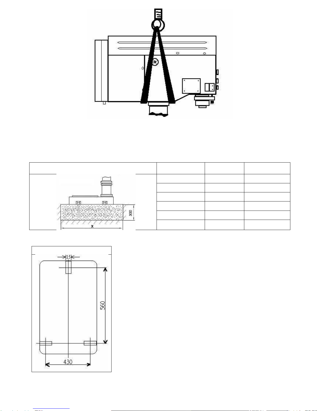
4. It shall be stable and securely fixed in machine installation procedure for the machine to be used
safety.
5. The working piece must betightlyfixedontableby vise or clamp.
6. Use recommended cutting liquid, consult the owner’s manual for recommended.
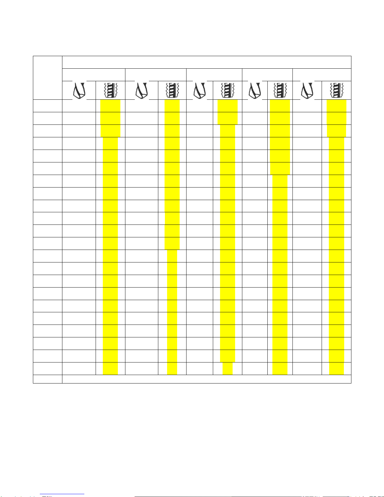
7. Feed speed should be executed undersafety scope, please refer to manual 3-3.
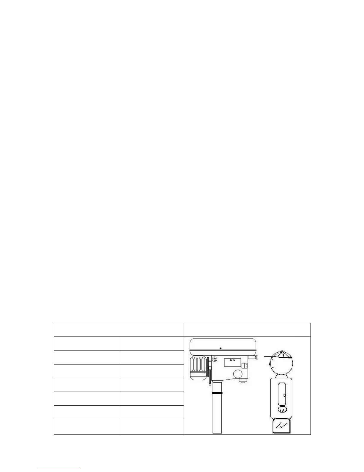
8. Wear proper apparel, no loose clothing, gloves, neckties, ring, bracelet to get caught in operation.
Always wear safety glasses,cap and specific clothes.
9. Check all parts are in place and securely locked before transportation. Bump and crash are
prohibited.
10.Routing maintenance and repaired should be executed follow the rules of manual.
11.Recommended use the industrial suction to clean the chip .
12.Recommended move the working piecewhich the weight over 10 kg used carrier move it.
13.Recommended wear safety gloves when install the drilling bit or tooling to avoid hurt yourhand.
14.This machine onlybe used following materialbrass, castiron,steel,iron, aluminum .
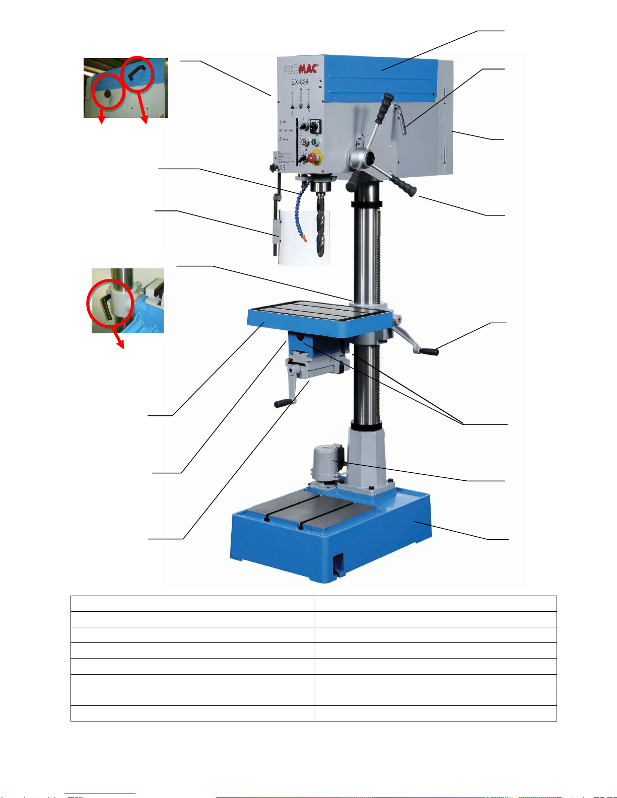
15.It isprohibited toopenthepulleycoverinoperation.
16.It isprohibited touse damagedor crackedparts
17.It is prohibited to removed the guard cover awayin operation.
4

18.It is prohibited to move the tablewhen machine in operation.
19.It is prohibited to operate this machine beyond the limit of its capacity,
20.Refer tothis instructionfordetails.
21.It isprohibited toinsert one'shandor finger intothe hole of working piece inoperation.
22.It is prohibited all visitors and children should stand near work area while the machine in operation.
23.It is prohibited to wear gloves,neckties, ring, bracelet and loose clothing in operation.
24.It is prohibited to use plastic and wooden working.
25.Checkagain before switch on power,
A-Makesure the powervoltage isfor the machine.
B- Make sure the machine is completely assembled and installed
C- Make sure chuck, workingtable,workingpiece are completelysecured ortightlyfixed.
D- Makesurethechuck keyis removedfromchuck.
E- Makesuredrill bitor toolingneedtobe fixed inthechuck.
26.Switch off power at once;
A-When fixed or removed working piece.
B-When the normal maintenance, service , adjustmentor repairing.
C-When the operatorleave the machine.
D-When corrected work table adjustment and depth position.
E-Whenchange or removethedrillingbit ortooling.
27.Working temp.5 --- 40℃,Humidity40---50,Elevation 0 ---1000 M
Storagetemp -25---55℃
28.Operate location diagramforreference.
Diagram1
Diagram2
MODEL
Ultimate loading
BX-834
70 kg
BX-834V
70 kg
BX-840VB
50 kg
5

3-1. Control panel instruction:
BX-834 only
A. Jkm Cam Switch (high/low)
B. Start Button
C. Emergency Stop Button
D. Feed DepthAdjustment
E. Drill / Tap Switch
F. Stop Button
G. Cutting Liquid Control Switch
For BX-834V or BX-840VB
A. min-1 or /min (R.P.M.) Indicator
B. Speed Control Switch
C. Fault light
D. Start Button
E. Emergency Stop Button
F. Feed DepthAdjustment
G. Drill / Tap Switch
H. Stop Button
I. Cutting Liquid Control Switch
6

3-2. Operation illustration and procedure:
1. Drill /Tap switch : For changing the machine to DrillMode or Tap Mode.
2. Work table and viseadjustment (for BX-834V/ BX-834 only)
Loose the work table and vise set screw then turn the work table 180 degree, let the
vise be upside. Then completely tight the set bolt.
3. There aretwo Tgrooves intheworktable.It isusedtofixthework piece.
4. There are two T grooves in the base, too. It is convenient for fixed the longer, heavier and larger
workingpiece.
5. Spindle speed adjustment is controlled by the speed control switch. The speed will be showed
outin the electronic digital meter. (for BX-834V/BX-840VB only)
6. Thebelt tension could be adjusted by a quickly crank in theright side of themachine head.
7. Thepulley cover is strictlyprohibited to open in normal operation condition.
8. Do not adjust the worktablewhen machine in operation.
9. Protect safety guard shall be allocated in a proper position in operation. It is controlled by a
micro witch.
10. If it needs to stop urgently, just push the emergency stop switch.
11. These machines havespecial design for tapping, aquick change device.
During tapping, if you want spindle to turn reversely and withdraw tapping tip, just pull up grip
handleonly. If you want to continueto operate, just press down grip handle.
Chuck Protection Guard
7

3-3. Operation tips:Speed Selection
Openpulleycaseandcheck ifspindlespeedmin-1or/min (R.P.M.)iscorrect for yourjob.
Recommended
Drill
m/m
Material
Cast Iron
Steel
Iron
Aluminium
Alloy Copper
2
4780
2390
1275
635
3980
1910
7960
3980
4460
2230
3
3185
1590
850
425
2650
1275
5310
2655
2970
1485
4
2390
1195
640
320
1990
955
3980
1990
2230
1115
5
1910
955
510
255
1590
765
3185
1590
1785
890
6
1590
795
425
210
1330
640
2655
1330
1485
745
7
1365
680
365
180
1140
545
2275
1140
1275
635
8
1195
600
320
160
995
480
1990
995
1115
555
9
1060
530
285
140
885
425
1770
885
990
495
10
955
480
255
125
800
380
1590
800
890
445
11
870
435
230
115
725
350
1450
725
910
405
12
795
400
210
105
665
320
1330
665
745
370
13
735
365
195
100
610
295
1225
610
685
340
14
680
340
180
90
570
270
1135
570
635
320
15
640
320
170
85
530
255
1060
530
600
300
16
600
300
160
80
500
240
995
500
560
280
17
560
280
150
75
470
225
935
470
525
260
18
530
265
140
70
440
210
885
440
495
250
19
500
250
135
67
420
200
835
420
470
235
20
480
240
130
65
400
190
795
400
445
225
25
380
190
100
50
320
155
640
320
355
180
30
320
160
85
45
265
130
530
265
300
150
40
240
120
65
30
200
95
400
200
225
110
note
Processingisadjustable onthe cuttingmaterials aswellasthematerialofthecuttingtorealcuttingconditions.
8

BX-834 / BX-834V / BX-840VB
1. Loosen knobs B on both sides of headstock.
2. Push handleAforward as arrow sign to get belt tension.
3.Lock knobs B firmly to fix belt tension.
Whenspeed changeisrequired. Loosen lead bolt(parts no.22-S2) on both side of headstock.Pull belt
handle (parts no.26) to allowbelts repositioning and then move belts to correct grooveto acquire
desired speed. See following speed chart for refeence.
For BX-834V
For BX-840VB
For BX-834
For BX-834 only
Forproper belt tension, use 10 1bs pressure or
hand pressure on the belt as shown as bellow. The
recommended distance is about 13mm.
9
B
A

3-4. Withdraw drill bit :
6
1. Bracketbar.
4. Completely insert bracket bar and ready for
operating.
2. Settinghole for bracketbar
5. Recommend to use special designed wedge for
withdrawingtooling
3. Insert bracketbar intosettinghole.
6. Don'tpush spindle stroke too long to avoid spindle
stick.
10

4.Operation procedure:
Caution Read instruction manual before operating the machine.
(1) Check thepowersource
Push the start button to judge the motor and spindle shaft is in normal conditionor not.
(2) Speed adjustment
After turn on the power, rotate the speed control switch form min. to max. position. When
rotation the switch, the speed will be changed and the speed value will be displayed in liquid
digital meter. (forelectronic LCD typeonly)
(3) Adjust work tableposition
Firstly, loose the clamp handle in left hand, then swing the table handle to properly position.
Finally tight the clamp handle.
(4) Adjust theheight of work tableto properly position,then fix the screw.
The worktable height depends on the working piece volume and height, if a incline angle is
necessary, loss the set screw first, then rotate the angle alignment the scale of the work table.
Finally, tight the set screw, if a vise will be used in the operation same as above, loose the set
screw, turn 180 degrees, let vise on theupside. Finally tight theset screw
(5) There are twoT grooves on the worktable. It is used to fix the workingpiece.
(6) There are two grooves in the base,too. It is convenientfor fixed the longer,heavier and larger
workingpiece.
(7) Secure the working piece on the worktable, as possible locatethe working piecein the center
ofthe worktable.
(8) Complete abovecautionitem and make sure no problem, then select theproperly toolfor
operation. Refer instruction manual suggestion adopt corrected cutting feed.
(9) Use Spindle Pulley to choose High or Low speed if 2-spped motor is equipped
to the machine.
(10) Before operation, the protected safety guard shall be pushed to proper position. Thereis a
micro switch in guard, the powerwill be shut down, when guard doesnot close well or not
in specified position.
11

5.Trouble –Shooting ;
Warning: Switch off power and remove plug from powersource outlet before trouble shooting.
NO.
SYMPTOM
DISPOTITION
1
Drill insert in working piece
and spindleshaft stop
1. Push emergency button
2.Turn offthepower
3. Use hand to turn thespindle shaft countermarch.
Let thetool withdraw fromthe working piece.
4.Suctionthechipon thehole.
5.Turn on power again.
6.Adopt slowly feed make sure in normal
condition then recovery the normal feed.
2
Cutting liquid in abnormal
condition and can not supply
theadequatequantity.
1. Check the pump is running or not
2. Check the hose is leakage, jamorcutting liquid
lacked.
3
Spindle shaft can not running
completely
1. Check the belt tension condition
2.If belt tensionis tooloose adjustthebeltshifter,
otherwise change theagingbelt.
4
Motor do not work
1. Check the power and switch
2. Check the power cable is damaged or not if
cableis broken, change itdirectly.
5
Spindle shaft has noise
1. Check bearing
2.CheckV–belt,if tightlydegreeoverspecific
tension will causenoise.
6
Drilloscillation
1. Check chuck condition
2. Make sure the drill is properlyfixed in the
chuck.
12

6.Maintenance:
Warning: Switch off power and remove plug from powersource outletbefore maintenance.
RECOMMENDEDUSEISO68LUBRICANT.
NO
MAINTAINPARTS
ITEM
PERIOD
DISPOTITION
1
Columnshaft
10 days
Add lubricant
2
Worktable
Everyday
1. Remove and clean the chip
2.Addrust-proof oil
3
Worktable
Everyday
1.Avoidtohitor collapsethe surfaceof work table
4
Worktable/ column
base
Everyday
1. After operation the table should be adjusted to
original position to prevent the deformation
occurs
5
Column
Everyday
1. Cleaning the stain from the column
2.Addlubricanttopreventrust
3. Strictly to hit the column if have any caved in
surfaceneed to repair itatonce
6
Control panel
Everyday
1. Clean the cutting liquid or oil stain
7
Power Cable
1 week
1. Check the cable configuration if damaged or
broken change it
8
Pump
First time
1. Check the running direction
2. Ifreverserunningchangetwophase wire.
9
Cutting liquid
3 Month
1.Attention the liquid level and chemical reaction
10
Motor
3 Month
1.clean the dust and void water spray to inner wire
11
Base
Everyday
1. clean and add rust –proof oil
12
Belt
1 week
1. Check belt tension and aging status
13
Pinion
1 week
1. Clean the dust and chip then add lubricant
14
Attachmentandparts
1 Month
1.Always keepcleaning.
2.Add rust-proof oil.
15
Pulleycover
1 week
1.Check loosing and fitting.
16
quill
Everyday
1.Check loosing and fitting.
2.Add lubricant.
17
Rack
1 week
1.Clearn the dust and chip.
2.Add lubricant.
18
Micro switch
emergencystopswitch
Everyday
1.Check on - off action.
2.If anydamagedorbroken.
prohibited operate machine.
and, repair it at once.
Modelsbeltmodel tables
13
Machine model
Beltspecifications
Quantity
BX-834
5340
2
BX-834V
5PK 1335
1
BX-840VB
5PK 1495
1

7.Specification and sound pressure;
Model
Item
BX-834
BX-834V
BX-840VB
Drillingcap.(mm)
32
40
M4 ~ M20
M4 ~ M20
Swing(mm)
460mm
600
Spindletaper
M.T.#3
M.T.#4
Spindletravel(mm)
140mm
145mm
No ofspindlespeed
9 ×2 Steps
Variable Speeds
Variable Speeds
Spindle speed(rpm)
50 Hz
105–2650/min
80 –2500/min
70 –2000/min
Column diameter(mm)
102mm
115mm
Table size(m/m)
T 320 × 480mm
T 400 × 470mm
Basesize(mm)
T 660 × 465 mm
T 660 × 465 mm
Motor
1.1kW 400V 3Ph
1.5kW 400V 3Ph
2.2kW 400V 3Ph
Netweight (kgs)
N.W-305Kg
N.W-295Kg
N.W-300Kg
Packing dimension(mm)
1110 × 570 × 2030mm
1160× 570×2060mm
Measurement
45.4 CU.FT
48.1 CU.FT
Packingcartonspermachine
1
1
BX-834
BX-834V
BX-840VB
A
1810
1900
B
330
347.5
C
230
230
D
880
1100
E
720
715
F
1130
1145
G
1000
1050
H
230
300
A- weightedsoundpressurelevelmeasuring undernoload
Drilling-series
Operator position
Lpa=
62
dB(A)
A-weightedsoundpressurelevel measuring underload
Drilling-series
Operator position
Lpa=
64
dB(A)
14

8. Control circuit diagram and component part list;
15

PARTS LIST BX-834V/BX-840VB
Part No.
Component/Object
Type/
Model
Ratings/
TechnicalData
PCS
Complieswiththe
followingstandard
Marksof
conformity
granted
CS
GENERALON/OFF
SWITCH
ZH-C316
AC 440V16A
1
EN60947
CE
KA1
CONTACTOR
C-12D
AC 440V/24V/12A
1
IEC947-4-1
CEULSA
KA2
CONTACTOR
C-12D
AC 440V/24V/12A
1
IEC947-4-1
CEULSA
TR
TRANSFORMER
SL-2930N
AC400V/24V7.2VA
1
IEC61558-1/-2-4
CE
SB1
PUSHBUTTON
GBF-22
INOAC125V,6A
1
IEC144
CSACE
SB2
PUSHBUTTON
GBF-22
INCAC 125V, 6A
1
IEC144
CSACE
SB3
SELECTION
SWITCHPUMP
GLCS-22
INCAC 125V, 6A
1
IEC144
CSACE
LR108205-2
SB4
SELECTION
SWITCH
(DRILL/TAP)
GCS-22
INAAC125V,6A
1
IEC144
CSACE
LR108205-2
SB5
EMERGENCY
STOP
GLEB-22
INCAC 125V, 6A
1
IEC144
CSACE
LR108205-2
VFD-E
INVERTER
VFD-E
AC 400V/ 1.5kW
AC 400V/ 2.2kW
1
EN 50178
EN 61800-3
CE
EMC
U2
BRAKING
RESISTOR
QSOJ013
200W250Ω
1
VR
SPEEDADJUSTING
KNOB
RV24YN
DC 10V
1
M1
MOTOR
MAINSPINDLE
BX-834V
BX-840VB
1.5kW /AC 400V/3Ph
2.2kW /AC 400V/3Ph
1
M2
MOTOR
PUMP
8150
0.1kW/AC 400V/3Ph
1
M3
MOTOR
COOLING FAN
UF-12A38
AC 400V/ 1PH
1
SQ1
MICOR SWITCH
CHUCKGUARD
VS10N001C2
AC 250V/ 10A
1
SQ2
MICOR SWITCH
COVER GUARD
QKS8
AC 250V /12A
1
VDE0660
EN60947-5-1
SQ3
LIMITSWITCH
TAPPING
Z-15GW2-B
AC 250V/ 15A
1
EN 61058-1
VDE
SQ4
LIMITSWITCH
REVERSE
VX-5-1A2
AC 250V/5A
1
VDE
XP
SOCKET
TBC-20
AC 600V/10A
16
UL
F1.F2.F3
FUSE STE
MFB-103
FUSE-F1.F2-0.5A
FUSE-F3-3A
3
KR1
RELAY
BMY5-2C5-S-
CWL
24VAC/28V5A
1
AL
Fault
PLN22Y24
AC 30V,0.5A
1
IEC144
CSACE
RPM
RPMDISPLAY
UNIT
RPM108
440V
1

16

17
PARTS LIST BX-834
Part No.
Component/Object
Type/
Model
Ratings/
TechnicalData
PCS
Complieswiththe
followingstandard
Marksof
conformity
granted
CS
GENERALON/OFF
SWITCH
ZH-C316
AC 440V16A
1
EN60947
CE
MR
CONTACTOR
KNL9-01
AC 440V/24V/12A
1
IEC60947-4-1
CEULSA
MF
CONTACTOR
KNL9-01
AC 440V/24V/12A
1
IEC60947-4-1
CEULSA
OL
OVERLOAD
NTH-6.5
AC 600V6A(4.5-6.5A)
1
IEC60947-4-1
CEULSA
MSR
RELAY
JQX-13F
AC24V5A
1
CEULSA
MS
RELAY
BMY5-2C5-S-
CL
24VAC/28V5A
1
CEULSA
SB1
PUSHBUTTON
GBF-22
INOAC125V,6A
1
IEC144
CSACE
SB2
PUSHBUTTON
GBF-22
INCAC 125V, 6A
1
IEC144
CSACE
SB3
SELECTION
SWITCHPUMP
GLCS-22
INCAC 125V, 6A
1
IEC144
CSACE
LR108205-2
SB4
SELECTION
SWITCH
(DRILL/TAP)
GCS-22
INAAC125V,6A
1
IEC144
CSACE
LR108205-2
SB5
EMERGENCY
STOP
GLEB-22
INCAC 125V, 6A
1
IEC144
CSACE
LR108205-2
L/H
CAM SWITCH
AC-22A
AC600V20A
1
IEC60947-3
CSACE
M1
MOTOR
MAINSPINDLE
BX-834
1.1kW /AC400V/3Ph
1
M2
MOTOR PUMP
8150
0.1kW/AC 400V/3Ph
1
SQ1
MICOR SWITCH
CHUCKGUARD
VS10N001C2
AC 250V/ 10A
1
SQ2
MICOR SWITCH
COVER GUARD
QKS8
AC 250V /12A
1
VDE0660
EN60947-5-1
SQ3
LIMITSWITCH
TAPPING
Z-15GW2-B
AC 250V/ 15A
1
EN 61058-1
VDE
SQ4
LIMITSWITCH
REVERSE
VX-5-1A2
AC 250V/5A
1
VDE
XP
SOCKET
TBC-20
AC 600V/10A
16
UL
TR
TRANSFORMER
SL-2930N
AC400V/24V7.2VA
1
IEC61558-1/-2-4
CE
F1.F2.F3
FUSE STE
MFB-103
FUSE-F1.F2-0.5A
FUSE-F3-3A
3
18
This manual suits for next models
2
Table of contents
Other Promac Drill manuals

Promac
Promac MDA-35Q User manual

Promac
Promac BX-834VS User manual

Promac
Promac MDA-55Auto User manual

Promac
Promac 930E User manual

Promac
Promac MDA-35 User manual

Promac
Promac FX-820VA User manual

Promac
Promac JDT-3216V User manual

Promac
Promac MDA-35S User manual

Promac
Promac JMDT-764016 User manual

Promac
Promac JMDT-763016 User manual