Promac BX-834VS User manual

BX-834VS
Instruction Manual
CAUTION: BEFORE USING THR MACHINE BE SURE TO READ THIS MANUAL
20181001

Contents of Manual:
1-1. Unpacking -------------------------------------------------------------------1
1-2. Transportation instruction ---------------------------------------------1
1-3. Setting the machine instruction -------------------------------------2
1-4. Major parts--------------------------------------------------------------------3
1-5. Items Needed for Set Up------------------------------------------------4
1-6. To assemble the drill chuck and mount it to the spindle---5
2. Safety instruction---------------------------------------------------------6-8
3-1. Control panel instruction ----------------------------------------------9
3-2. Operation illustration and procedure-----------------------------10-12
3-3. Operation tips and sound pressure ------------------------------13-14
3-4. Withdraw drill bit ---------------------------------------------------------15
4. Trouble - Shooting ------------------------------------------------------16
5. Maintenance ---------------------------------------------------------------17
5-1. Feed Shaft Spring Tension--------------------------------------------18
6. Specification ---------------------------------------------------------------19
7. Control circuit diagram and component part list ------------20-21
8. Drawing and parts list --------------------------------------------------22-25

1
1-1. Unpacking:
Before unpacking, make sure the carton configuration not damaged, broken or parts extruded, if any
above defect case is found, contact your retailer to change a new one as soon as possible.
Unpacking procedure:
1. Carefully open the carton. (Pull it from the bottom to the top)
2. Take out and read the manual, check parts list and relative attachments.
3. Inspect the machine outline if it is in normal condition or not. Crack, rust, collapse and separate
are strictly prohibited.
4. Cleaning the surface of the machine.
5. Assemble the drill machine based on manual, instruction guide.
1-2. Transportation instruction:
1. Please refer to instruction manual in specification and machine weight to arrange handling
manner. Be sure to use capable fork – lifter or hoist to lift of machine.
2. The handling and transportation shall be carried out by qualified persons.
3. Fork – lift or hoist can be used in handling and shall be operated by qualified driver.
4. While transportation, keep attention to the balance of machine.
5. During handling, the machine shall be lifted only in vertical direction.
6. Before handling, make sure all movable parts are secured in their position and all movable
accessories should be removed from machine.
7. The steel rope should average pull the machine head, table and column tightly.
8. Keep all the processes in a carefully and slightly condition.
9. Bump or crash are strictly prohibited. It will cause precision shift and electronic controller
damaged.

2
Typical lifting strap position.
1-3. Setting the machine instruction:
1. The machine base with setting hole will be set on concrete floor.
The outlined procedures of setting the machine
MODEL
AREA
SETTED SCREW
BX-834VS
X=900×700
M12
2. The dimension of setting hole:
Consider existing and anticipated needs, size of material to be processed through each machine, and
space for auxiliary stands, work tables or other machinery when establishing a location for your
machine. See Figure 01.
BX-834VS Dimensions(m/m)
BX-834VS
A=1000
B=560
Lifting Straps
Figure 01

3
1-4. Major Parts:
A= Pulley Cover
I= Vice 4”
B= Motor Handle
J= Vice Lock
C= Switch cover
K= Table
D= Feed Handle
L= Clamp Handle
E= Table Handle
M= Safety Guard
F= Table Lock
N= Pump Valve Lock
G= Pump Motor
O=Belt Tension Lock
H= Base
P=Belt Cover Handle
O P
C
D
K
E
H
M
A
B
I
G
L
F
J
N

4
1-5. Items Needed for Set Up
1.The downfeed handles must be installed to operatethe drill press.
To install the downfeed handles:
Thread the handles into the spindle hub, as shown in Figure 02, and tighten.
2.Install the crank lever over the pinion shaft,and tighten the setscrewin the crank handle against the flat
partofthepinion shaft. Figure 03,
3. The drill chuck attaches to the spindle by means of the arbor, shown in Figure 04. Matched tapers on
the arbor and the inside of the chuck create a semipermanent assembly when properly joined.
Figure 03
Flat part
Arbor
Drill shifter
Figure 04
Hex Wrench 4mm
Figure 02
Downfeed handles
Spindle Hub
Wrench
Size 12mm
Locked to the reference line

5
1-6. To assemble the drill chuck and mount it to the spindle:
1. Use mineral spirits to thoroughly clean the drill chuck, arbor, and spindle sockets and dry all surfaces
before assembly. Follow all safety warnings on the container of the mineral spirits. Failure to clean the
mating surfaces may cause the tapered fit to loosen during operation, resulting in separation and an
unsafe condition. Figure 05.06.07
2. Use the chuck key to adjust the jaws of the drill chuck until they are inside the drill chuck body.
Figure 08.09
3. Place the drill chuck face down on a workbench. The arbor has a short taper and a long taper. Place
the short taper into the socket in the back of the drill chuck and tap it with a rubber or wooden mallet, as
shown in Figure 10. If the chuck fails to remain secure on the arbor, repeat Steps 1 & 2.
4. Slide the arbor into the spindle socket while slowly rotating the drill chuck. The socket has a
rectangular pocket where the tang (or flat portion of the arbor shown in Figure 10) fits into.
5. Seat the chuck with a rubber mallet, as shown in Figure 11.
Figure 05
Figure 06
Figure 07
Figure 08
Figure 09
Figure 10
Figure 11
Wood
Tang-SideUp

6
2. Safety Instruction:
Please read the safety instruction and operation instruction
carefully.
Please do wear a safety glass to avoid any material from
coming into the eyes whilst operation.
Please do wear ear mufflers or earplugs to avoid any noise
from hurting the listening whilst operation.
Please do wear proper work clothing whilst operation.
Loose clothing or tie are prohibited to avoid any
unnecessary incident.
If a operator has long hair, please do fix the hair or use cap
to avoid the hair from being drawn into it.
A processing workpiece shall be fixed firmly to avoid it
from being thrown out whilst operation.
Please keep both hands far from the rotating tool whilst
operation. Cotton gloves are prohibited to avoid from being
drawn into cutter.
Please pull out the power plug to avoid any electric shock
incident whilst product maintenance or repair.

7
Read Instruction Manual before operating the machine for your own safety.
1. Make sure the power voltage is for the machine. Before connecting the plug to socket, it is necessary
to check the power spec. to avoid any damage occurring.
2. If the machine is not used for a long time, the plug should be disconnected.
3. Never put the power cable near the fire or water environment, to break or press the power cable is
not allowed.
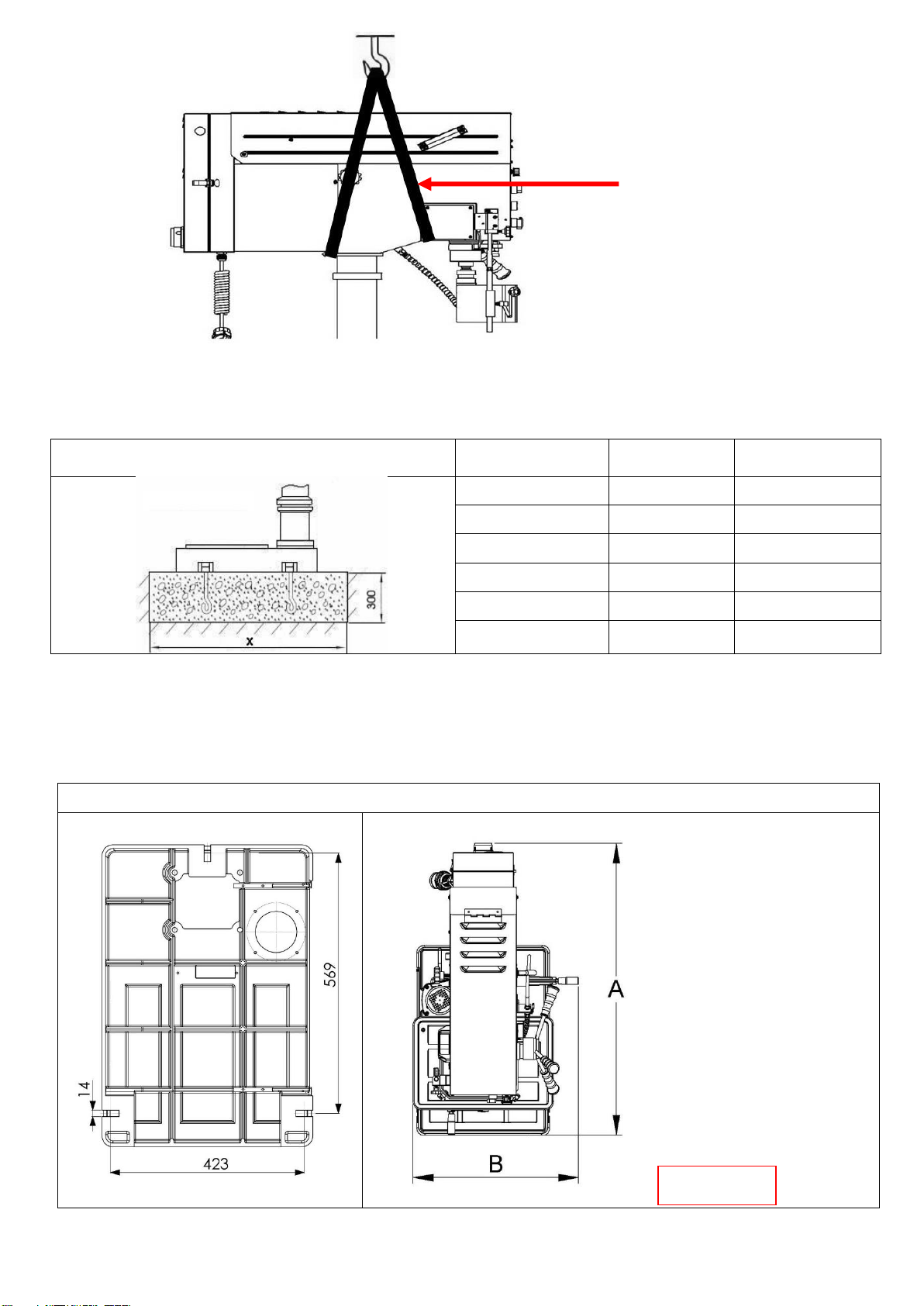
4. It shall be stable and securely fixed in machine installation procedure for the machine to be used
safely.
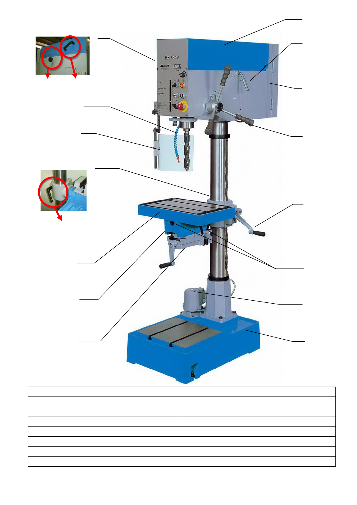
5. The working piece must be tightly fixed on table by vise or clamp.
6. Use recommended cutting liquid; consult the owner’s manual for recommendation.
7. Feed speed should be executed under safety scope, please refer to manual 3-3.
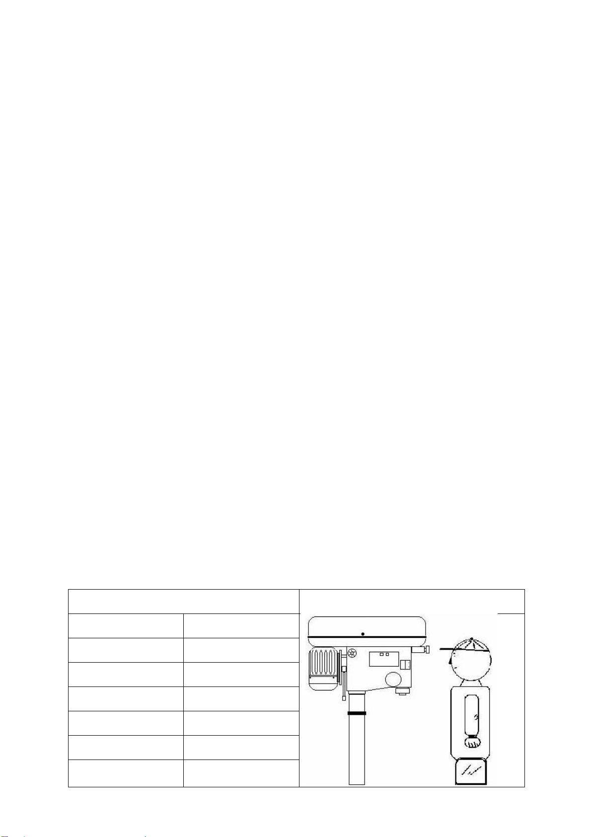
8. Wear proper apparel, no loose clothing, gloves, neckties, ring, and bracelet during operation. Always
wear safety glasses, cap and specific clothes.
9. Check all parts are in place and securely locked before transportation. Bump and crash are
prohibited.
10. Regular maintenance and repaired should be executed in accordance with the rules of manual.
11. Use the industrial suction to clean the chip is recommended.
12. Use carrier to move the working piece which the weight is more than 10 kg is recommended.
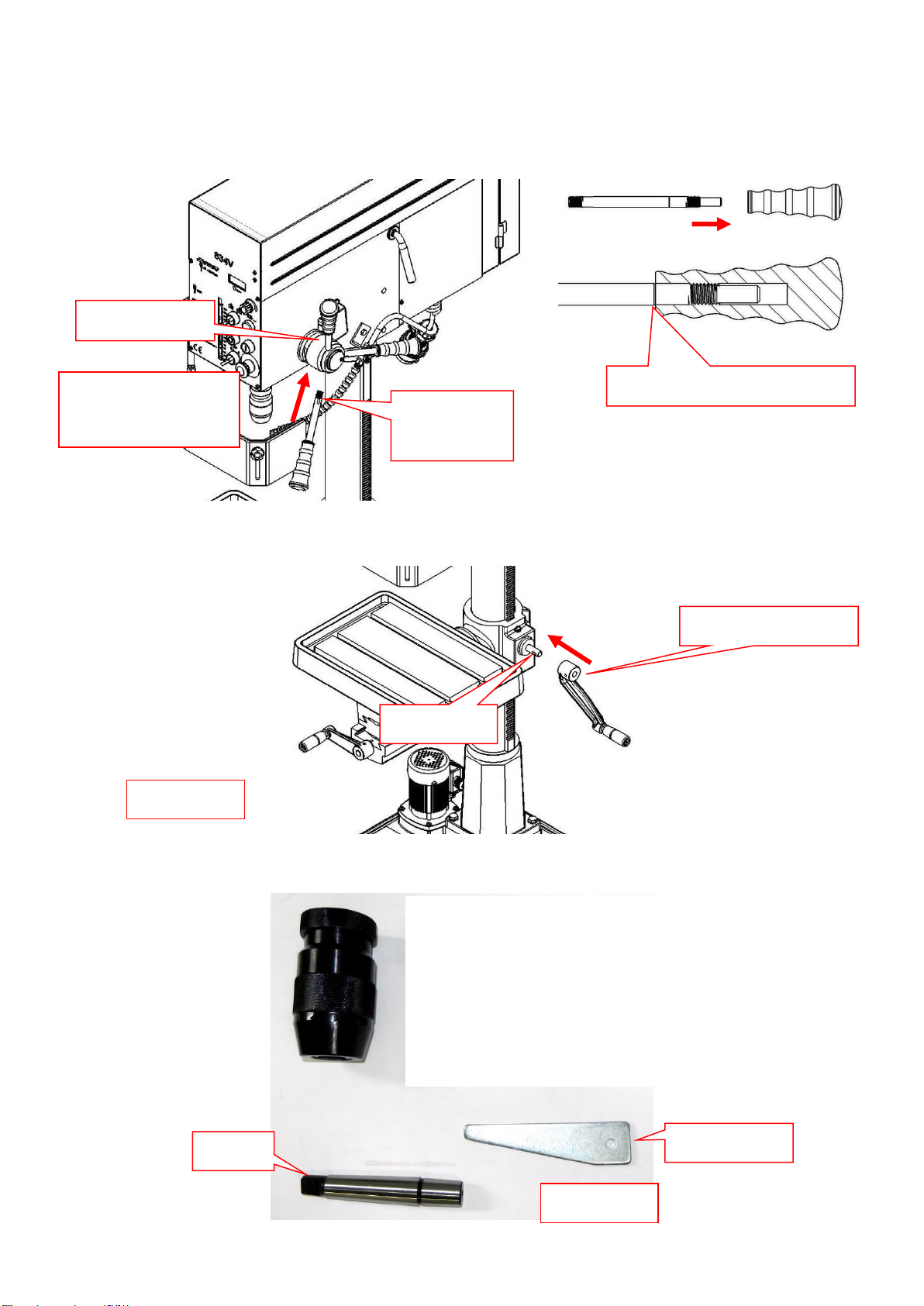
13. Wear safety gloves when install the drilling bit or tooling to avoid hurting your hand is
recommended.
14. This machine only be used following material brass, cast iron, steel, iron, aluminum .
15. It is prohibited to open the pulley cover during operation.
16. It is prohibited to use damaged or cracked parts
17. It is prohibited to remove the guard cover away during operation.

8
18. It is prohibited to move the table when machine is during operation.
19. It is prohibited to operate this machine beyond the limit of its capacity.
20. Refer to this instruction for details.
21. It is prohibited to insert one's hand or finger into the hole of working piece during operation.
22. It is prohibited all visitors and children should stand near work area while the machine during
operation.
23. It is prohibited to wear gloves, neckties, ring, bracelet and loose clothing during operation.
24. It is prohibited to use plastic and wooden working.
25. Check again before switch on power,
A- Make sure the power voltage is for the machine.
B- Make sure the machine is completely assembled and installed
C- Make sure chuck, working table, working piece are completely secured or tightly fixed.
D- Make sure the chuck key is removed from chuck.
E- Make sure drill bit or tooling need to be fixed in the chuck.
26. Switch off power at once;
A- When fix or remove working piece.
B- When the normal maintenance, service, adjustment or repairing.
C- When the operator leaves the machine.
D- When correct work table adjustment and depth position.
E- When change or remove the drilling bit or tooling.
27. Working temp.5 --- 40℃,Humidity 40--- 50,Elevation 0 ---1000 M
Storage temp -25--- 55℃
28. Operate location diagram for reference.
Diagram 1
Diagram 2
MODEL
Ultimate loading
BX-834VS
70 kg

9
3-1. Control panel instruction:
BX-834VS
A. min-1 or /min (R.P.M.) Indicator
B. Speed Control Switch
C. Fault light
D. Start Button+ light
E. Emergency Stop Button
F. Feed Depth Adjustment
G. Drill / Stop / Tap Switch
H. Stop Button
I. Cutting Liquid Control Switch
J. LED Work Lamp Switch (Option)
1. Check the power source
Push the start button to judge the motor and spindle shaft is in normal condition or not.
2. Spindle speed adjustment is controlled by the speed control switch. The speed will be
showed out in the electronic digital meter.
3. If it needs to stop urgently, just push the emergency stop switch.
4. Drill / Tap switch: For changing the machine to Drill Mode or Tap Mode.
BX-834VS
J

10
3-2. Operation illustration and procedure:
1. There are three T grooves in the worktable. It is used to fix the work piece.
1-1.There are two T grooves in the base, too. It is convenient for fixing the longer, heavier and larger
working piece.
(Option)
2. These machines have special design for tapping, a quick change device. During tapping, if you
want spindle to turn reversely and withdraw tapping tip, just pull up grip handle only(as shown
in Figure 12.) If you want to continue to operate, just press down grip handle. (as shown in
Figure 13.)
3. Protect safety guard shall be allocated in a proper position in operation. It is controlled by a micro
witch.
Figure 12
Figure 13
Lock
Loose

11
4. Adjustment of feeding limit
To prevent unwanted penetration to work piece, the feeding limit
shall be set by adjusting the appropriate position of feeding depth
fixing button as long as the distance between the end of tool and
top surface if work piece is measured.
A. Setting of feeding depth Feed Depth Adjustment
5.Work table and vise adjustment
Loose the work table and vise set screw then turn the work table 180 degree, let the vise be upside.
Then completely tight the set bolt. Figure 14.15.16.17
6.Please open water outlet valve and adjust a proper water outlet volume after power supplying. Fig 18
Figure 14
Figure 15
Figure 16
Figure 17
Figure 18
Loose
Loose
Lock
Wrench Size 19m
A

12
7. Adjust work table position
(1)Firstly, loose the clamp handle in left hand (Figure 19)
(2)Then swing the table handle to properly position. (Figure 20)
(3)Finally tight the clamp handle. (Figure 19)
8. Pulley Cover Open and Close Method
(1)Open iron cover—hold the handle of left iron cover (Figure 21 A) and push upward to the highest point and then release
slightly; use locator (Figure 22 B) to fix the iron cover as open state.
(2)Close iron cover-- hold the handle of left iron cover (Figure 21 A) and push upward to the highest point; pull locator
(Figure 22 B) forward to release the fixed state and then lower down the iron cover slightly to the original position. (The
motor power can not be started when the iron cover opens.)
9. Draw bar Application Method
TakeDrawbartoloadthespindleaccordingtothe indicationpositionin Figure 23.Drawbarcanavoid
TappingChuck(option)fallingdown fromthespindleduetosuddenreverseduringthe processing, especially
while processingM12above.
Figure 19
Figure 20
Figure 23
Figure 21
Figure 22
A
A
B
Draw bar

13
3-3. Operation tips and sound pressure: Speed Selection
Open pulley case and check if spindle speed min-1or/min (R.P.M.) is correct for your job.
Recommended
Drill
m/m
Material
Cast Iron
Steel
Iron
Aluminium
Alloy Copper
2
4780
2390
1275
635
3980
1910
7960
3980
4460
2230
3
3185
1590
850
425
2650
1275
5310
2655
2970
1485
4
2390
1195
640
320
1990
955
3980
1990
2230
1115
5
1910
955
510
255
1590
765
3185
1590
1785
890
6
1590
795
425
210
1330
640
2655
1330
1485
745
7
1365
680
365
180
1140
545
2275
1140
1275
635
8
1195
600
320
160
995
480
1990
995
1115
555
9
1060
530
285
140
885
425
1770
885
990
495
10
955
480
255
125
800
380
1590
800
890
445
11
870
435
230
115
725
350
1450
725
910
405
12
795
400
210
105
665
320
1330
665
745
370
13
735
365
195
100
610
295
1225
610
685
340
14
680
340
180
90
570
270
1135
570
635
320
15
640
320
170
85
530
255
1060
530
600
300
16
600
300
160
80
500
240
995
500
560
280
17
560
280
150
75
470
225
935
470
525
260
18
530
265
140
70
440
210
885
440
495
250
19
500
250
135
67
420
200
835
420
470
235
20
480
240
130
65
400
190
795
400
445
225
25
380
190
100
50
320
155
640
320
355
180
30
320
160
85
45
265
130
530
265
300
150
40
240
120
65
30
200
95
400
200
225
110
note
Processing is adjustable on the cutting materials as well as the material of the cutting to real cutting conditions.
A- weighted sound pressure level measuring under no load
Drilling-series
Operator position
Lpa=
62
dB(A)
A-weighted sound pressure level measuring under load
Drilling- series
Operator position
Lpa=
64
dB(A)

14
BX-834VS
1. Loosen knob B on both sides of headstock.
2. Push handle A forward as arrow sign to get belt tension.
3. Lock knob B firmly to fix belt tension.
When speed change is required. Loosen lead bolt (parts no. 22-S2) on both side of headstock. Pull belt
handle (parts no. 26) to allow belts repositioning and then move belts to correct groove to acquire
desired speed. See following speed chart for reference.
For BX-834VS
For proper belt tension, use 10 1bs pressure or hand pressure on the belt as shown as bellow. The
recommended distance is about 100mm.
Models belt model tables
Machine model
Belt specifications
Quantity
BX-834VS
5PK 1335
1
B
A

15
3-4. Withdraw drill bit :
6
1. Bracket bar.
4. Completely insert bracket bar and ready for operating.
2. Setting hole for bracket bar
4-1. Rotate the spindle until the inner drift-key slot is aligned with the
outer slot, as shown in (Figure 4-1). You will see through the
spindle when the slot is properly aligned.
3. Insert bracket bar into setting hole
5. Recommend to use special designed wedge for withdrawing tooling
6. Don't push spindle stroke too long to avoid spindle stick.
4-1
Both Slots
Aligned

16
4. Trouble – Shooting;
Warning: Switch off power and remove plug from power source outlet before trouble shooting.
NO.
SYMPTOM
DISPOSITION
1
Drill insert in working piece and
spindle shaft stop
1. Push emergency button
2. Turn off the power
3. Use hand to turn the spindle shaft countermarch. Let the
tool withdraw from the working piece.
4. Suction the chip on the hole.
5. Turn on power again.
6. Adopt slowly feed make sure in normal condition then
recovery the normal feed.
2
Cutting liquid in abnormal
condition and can not supply the
adequate quantity.
1. Check the pump is running or not
2. Check if the hose is leaking or not.
3
Spindle shaft can not running
completely
1. Check the belt tension condition
2. If belt tension is too loose, adjust the belt shifter,
otherwise change the aging belt.
4
Motor do not work
1. Check the power and switch
2. Check the power cable is damaged or not if cable is
broken, change it directly.
5
Spindle shaft has noise
1. Check bearing
2. Check V – belt, if tightly degree over specific tension
will cause noise.
6
Drill oscillation
1. Check chuck condition
2. Make sure the drill is properly fixed in the chuck.
7
Pump stop suddenlyorslowdown
1. Impeller is clogged.
2. Overloading protection device of motor starts.
3. Motor failure.

17
5. Maintenance :
Warning: Switch off power and remove plug from power source outlet before maintenance.
Everyday
1 week
1 Month
1 Month
NLGI #2 grease
oil
ISO 68 LUBRICANT
3 Month
Coolant : Soluble Metal Cutting Fluid.

18
5-1. Feed Shaft Spring Tension:
The feed shaft return spring is adjusted at the factory; however, during the life of the drill press you may
want to adjust the feed shaft return spring so the feed shaft return pressure suits your operating needs.
Toadjustthe feedshaftspringtension:
1.UNPLUGTHE DRILPRESS !
2. Wipe offany oil on thespring lock cover so it does not slip in your fingers when youhold the
cover fromspinning (see Figure25).
3. Whileholding the spring lock cover against the side of the head stock so the cover stays splined with
thelocking lug; loosen the jam nut and loosenthe cover nut approximately 1⁄4" (see Figure27).
4. Put on heavyleather gloves to protect your hands from possible lacerations if thespring uncoils
during thenextstep.
5. Pull thecover outward just enough to disengage the spring-cover lock slot fromthe locking lug. Note:
It is important to keepa good grip during this step. Letting go ofthe cover will cause the spring to
rapidlyuncoil.
6. Rotate the cover counterclockwise to increasespring tension, or let the cover slowly unwind in the
clockwisedirectionto reduce springtension.
7. Engagethe next available spring-cover lock slot with the locking lug and hold the spring lock cover
tightlyagainstthesideof theheadstock.
8. Snug the cover nut against the spring coverjust until thenut stops,and then back off the nut
approximately 1⁄3 turn, or just enough so there is no binding at complete spindle travel.
9. Hold the cover nutand tighten the jamnut against the cover nut.
Figure 24
Figure 26
Figure 27
Figure 25
Lock Nut
Spring Lock
Cover
Spring Cover
Lock Slot
Wrench
Size 19mm
Table of contents
Other Promac Drill manuals

Promac
Promac MDA-35 User manual

Promac
Promac FX- 388D User manual

Promac
Promac JMDT-763016 User manual

Promac
Promac JDT-3216V User manual

Promac
Promac MDA-35S User manual

Promac
Promac FX-820VA User manual

Promac
Promac BX-834 User manual

Promac
Promac MDA-35Q User manual

Promac
Promac JMDT-764016 User manual

Promac
Promac MDA-55Auto User manual
Popular Drill manuals by other brands

Black & Decker
Black & Decker KR703-XE manual

Harbor Freight Tools
Harbor Freight Tools 42977 Assembly & operating instructions

Batavia
Batavia BT-CCD003 operating instructions

Ryobi
Ryobi RPD1010 Original instructions

Makita
Makita DA4030 instruction manual

Stanley FatMax
Stanley FatMax FMCD900 Original instructions