Promeba PS-250 User manual
USER GUIDE
CHAIR PS-250 // POWER TRACK PA-260 //
LOCKING SYSTEM PA-270
Review 01/17


USER GUIDE //
CHAIR PS-250 + POWER TRACK PA-260 + LOCKING SYSTEM PA-270
Review 01/17
3
01 INTRODUCTION
01.1 Use of the manual 05
01.2 Technical sheet 06
02 INSTALLATION
02.1 Transport and unpacking 10
02.2 Anchor points 11
02.3 Electric connection 12
02.4 Start up of the track 13
03 OPERATION
03.1 General elements of chair PS-250 14
03.2 Elements of the chair manual system PS-250 15
03.3 Folding and unfolding the chair PS-250 16
03.4 Engaging and disengaging operation of track system 17
03.5 General elements of track PA-260 18
03.6 Elements of the track manual system PA-260 19
03.7 Operation of up and down stairs of the track system 20
03.8 Control Panel 21
03.9 Adjust the track to the stairs 22
03.10 Problem solving 23
03.11 General elements of locking system PA-270 24
03.12 Elements of the locking manual system PA-270 25
04 ASSEMBLAGE AND DISASSEMBLE
04.1 Exploded view of general chair set PS-250 26
04.2 General chair bill of materials PS-250 27
04.3 Exploded view of chair backrest set PS-250 28
04.4 Chair backrest set bill of materials PS-250 29
04.5 Exploded view of front legs chair set PS-250 30
04.6 Front legs chair set bill of materials PS-250 31
04.7 Exploded view of seat frame chair set PS-250 32
04.8 Seat frame chair set bill of materials PS-250 33
04.9 Exploded view of extensible left handle chair set PS-250 34
04.10 Left handle chair set bill of materials PS-250 35
04.11 Exploded view of extensible right handle chair set PS-250 36
04.12 Extensible right handle chair set bill of materials PS-250 37
04.13 Exploded view of general track set PA-260 38
04.14 General track set bill of materials PA-260 41
04.15 Exploded view of control panel track set PA-260 42
04.16 Control panel track set bill of materials PA-260 43
04.17 Exploded view of loading head track set PA-260 44
04.18 Load head track set bill of materials PA-260 45
04.19 Exploded view of support general set PA-270 44
04.20 Support general set bill of materials PA-270 45
04.21 Exploded view of loading head support set PA-270 44
04.22 Loading head support set bill of materials PA-270 45
04.23 Exploded view of top locking system set PA-270 44
04.24 Top locking system set bill of materials PA-270 45
INDEX
USER GUIDE //
CHAIR PS-250 + POWER TRACK PA-260 + LOCKING SYSTEM PA-270
Review 01/17
4
05 ELECTRIC DIAGRAM
05.1 Printed circuit board 53
05.2 Electrical wiring diagram 55
06 GENERAL MAINTENANCE 56
07 LEGAL NOTICES 57
08 PRODUCT WARRANTY 58
INDEX
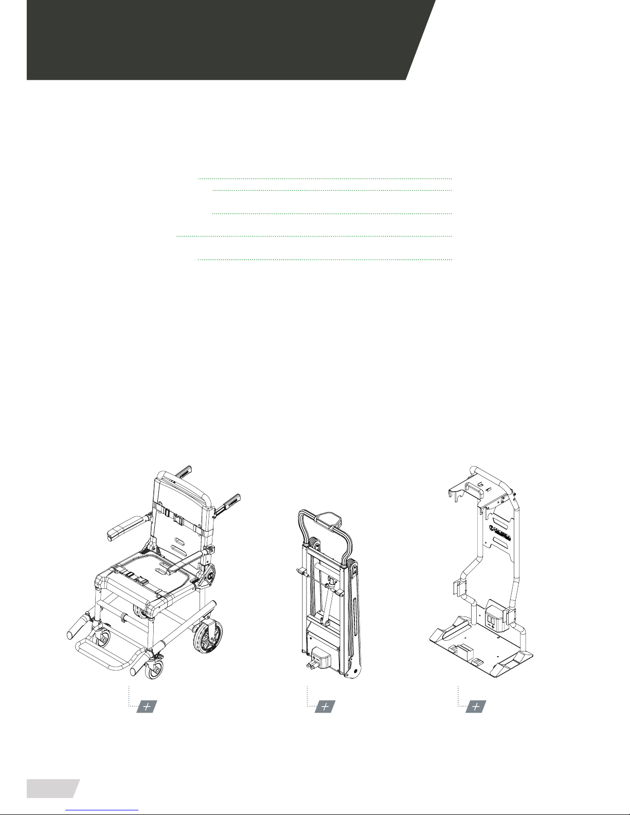
PS-250 MODEL
EMERGENCY CHAIR
PA-260 MODEL
POWER TRACK
PA-270 MODEL
SUPPORT WITH CHARIGING STATION

USER GUIDE //
CHAIR PS-250 + POWER TRACK PA-260 + LOCKING SYSTEM PA-270
Review 01/17
5
01.1 Use of the manual
The manual content includes instructions for use and
maintenance of the product, as well as how to solve mi-
nor breakdowns that may arise.
It is recommended before operating the product, this
manual should be carefully read to avoid deterioration
due to misuse.
Do not lose this document, it must be accessible to any
query that could arise by the health personnel.
Remember, a good use and maintenance are necessary
for the proper functioning of the product.
Each product has an identication sticker with the se-
rial number and model. Keep these numbers so you
can tell the distributor if necessary.
01 INTRODUCTION

USER GUIDE //
CHAIR PS-250 + POWER TRACK PA-260 + LOCKING SYSTEM PA-270
Review 01/17
6
01.2 Technical sheet
MEASURES AND CHARACTERISTICS // PS-250 EMERGENCY CHAIR
LENGTH 715 mm WHEELS 4 (2 WITH BRAKES)
WIDTH 550 mm ARMRESTS 2 (FOLDING)
HIGH 1025 mm REAR HANDLES 2 (BLOCKABLE)
FOLDED HIGHT 220 mm FRONT HANDLES 2 (5 POSITIONS)
WEIGHT 13 Kg SEAT HIGH 515 mm
MAX. LOAD 180 Kg SEAT MEASURES 430x460 mm
PERSONNEL REQUIRED 2 BACKREST MEASURES 440x440 mm
01 INTRODUCTION
515
170
220
395
360
715
430
217
1025
440
550
440
180
360
320
230
102º
USER GUIDE //
CHAIR PS-250 + POWER TRACK PA-260 + LOCKING SYSTEM PA-270
Review 01/17
7
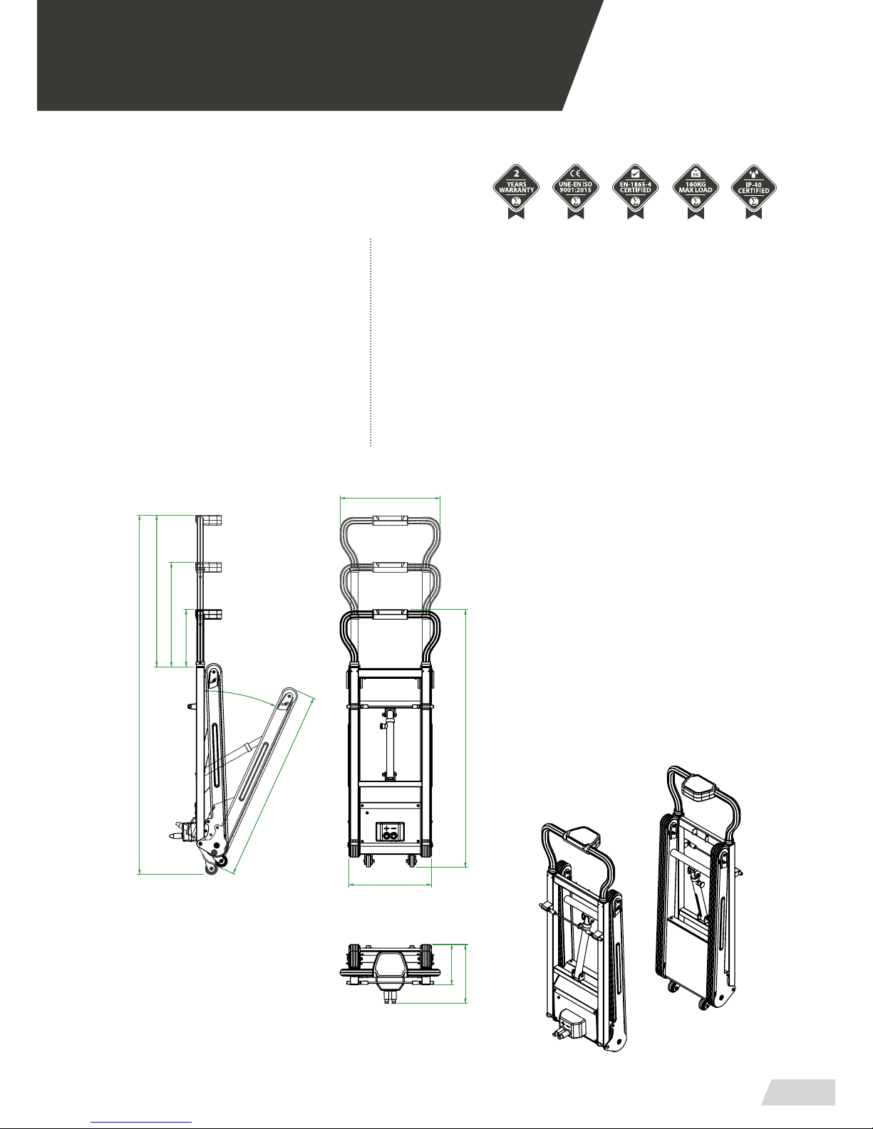
MEASURES AND CHARACTERISTICS // PA-260 ELECTRIC TRACK
LENGTH 250 mm ELECTRICAL POWER SUPPLY 12 V. CC. / 24V AC.
WIDTH 350 mm CONSUMED POTENCE 30A
HIGH MIN/MAX 1080-1520 mm PERSONNEL REQUIRED 2
WEIGHT 17 Kg LONG BELTS 820 mm
MAX. LOAD 160 Kg LOADING TIME 60 min
TEMP. MIN/MAX -20º/+40º TRANSPORT WHEELS 2x Ø50 mm
MAX. AUTONOMY 140min/130Kg LED LIGHTS 2x LENGTH 25CM
01 INTRODUCTION
200
1520
425
350
170
250
14-25-33º
400600
1090
820

01 INTRODUCCIÓN
USER GUIDE //
CHAIR PS-250 + POWER TRACK PA-260 + LOCKING SYSTEM PA-270
Review 01/17
9
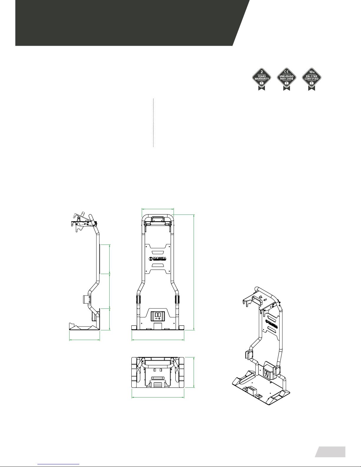
MEASURES AND CHARACTERISTICS // PA-270 SUPPORT WITH LOAD SYSTEM
LENGTH 310 mm ELECTRICAL POWER SUPPLY 12 V. CC.
WIDTH 535 mm CONSUMED POTENCE 30A
HIGH 1175 mm WORKING TEMPERATURE -20º/+40º
WEIGHT 17 Kg PERSONNEL REQUIRED 1
300
310
220 355
535
1175
535
310
325
01 INTRODUCTION

USER GUIDE //
CHAIR PS-250 + POWER TRACK PA-260 + LOCKING SYSTEM PA-270
Review 01/17
10
02 INSTALLATION
02.1 Transport and unpacking
First remove the packaging carefully so as not to dama-
ge the outside of the stretcher.
1. Transport
· Always x the load, if it is necessary stack. you should
follow the diagram shown.
· Transport the level load and following all the precepts
and regulations regarding the transport of loads.
2. Unpacking
· Put the box on a at and stable surface, open the seal
carefully not to damage inside.
· Remove the product from the inside of the case as
shown in the chart below.
Each product has been thoroughly inspected when
leaving the factory.To ensure that the transport has not
deteriorated it, please inspect the exterior and interior
carefully, and in the event of any damage, contact the
installer immediately.
PACKING UNIT
RESPECT THE PACKAGING TRANSPORT POSITION
UNPACKING THE PRODUCT
ALWAYS USE FLAT SURFACE

USER GUIDE //
CHAIR PS-250 + POWER TRACK PA-260 + LOCKING SYSTEM PA-270
Review 01/17
11
02 INSTALLATION
02.2 Anchor points
Before starting the chair+track set up, you must ensure
that each and every one of the anchor points are in pla-
ce and tightened.
LOCKING SYSTEM TO SUPPORT PA-270
(8 anchor points)
261
156,5 154
330
8,5 (X8)
102
67,8
149,5
531,3
149,5
250
235
102
***IMPORTANT FOR THE INSTALLATION***
FIXING SCREWS M8 S/NORMA DIN-7991 (8 UNITS)
BEFORE DRILLING, CHECK THE FIXING DOES NOT INTERFERE WITH DUCT OR PRE-EXISTING
WIRING IN AMBULANCE. THE ELECTRICAL INSTALLATION OF THE PRODUCT SHOULD BE
CARRIED WITH THE ELECTRONIC DEVICES OFF. USE THE USER MANUAL FOR ANY QUESTIONS
DURING YOUR INSTALLATION.
USER GUIDE //
CHAIR PS-250 + POWER TRACK PA-260 + LOCKING SYSTEM PA-270
Review 01/17
12
02 INSTALLATION
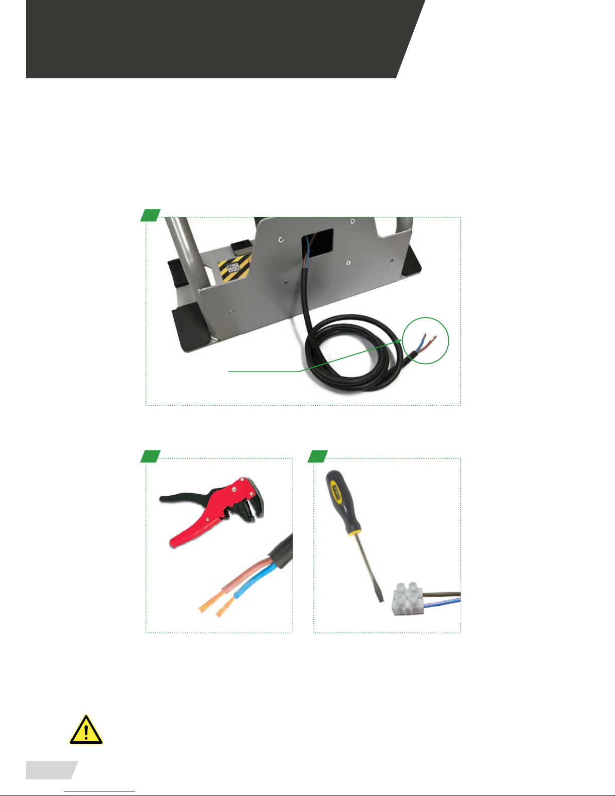
02.3 Electric connection PA-270
Follow the steps below to make the connection.
Take special care in connecting the support to the required voltage of 12V direct current and not
leaving the cables in areas of passage or with elements in movement, could cause breaks, cuts and
failures in the system.
A
Power cable
12V. CC.
B
Remove the plastic end of the BROWN
(+) and BLUE (-) cables with a wire pe-
eler in order to make the connection.
C
Use a power strip and a at - blade
srewdriver to connect the BROWN (+)
and BLUE (-) cables next to the ambu-
lance jacks.
To make the connection, locate the black cable on the back of the stand.
BE SURE TO HAVE THE POWER SUPPLY LINE PROPERLY PROTECTED AND THAT THE POWER
THROUGH THE LINE IS STABLE.
USER GUIDE //
CHAIR PS-250 + POWER TRACK PA-260 + LOCKING SYSTEM PA-270
Review 01/17
13
02 INSTALLATION
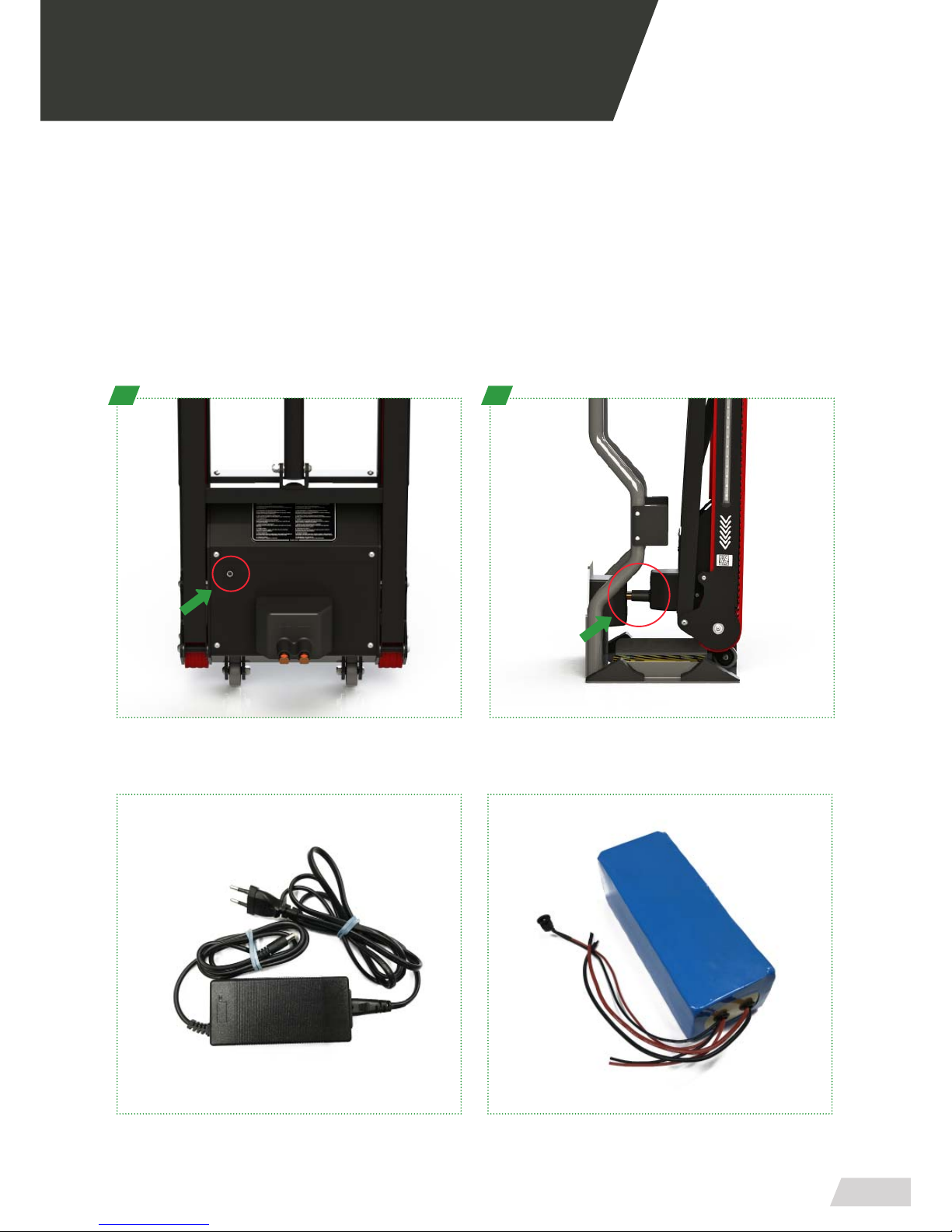
02.4 Start up of the track PA-260
To start using the power track, it is necessary to charge the battery. To do this, locate the external
socket with female connector 2.1, located on the back of the track as shown in the picture (A).
If you have the support PA-270 and you already have it installed, you can start loading the power
track as shown as in the picture (B), place the track in the holder and start charging automatically.
Always charge the battery up with the charger supplied by PROMEBA to its maximum charge level
(approx. 60min. are enough).
A
Only charge the batteries of the stretcher with the charger supplied by PROMEBA, otherwise it
could damage the batteries and you will lose their warranty.
B
External charger for PROMEBA battery. High performance battery for PROMEBA power track.
USER GUIDE //
CHAIR PS-250 + POWER TRACK PA-260 + LOCKING SYSTEM PA-270
Review 01/17
14
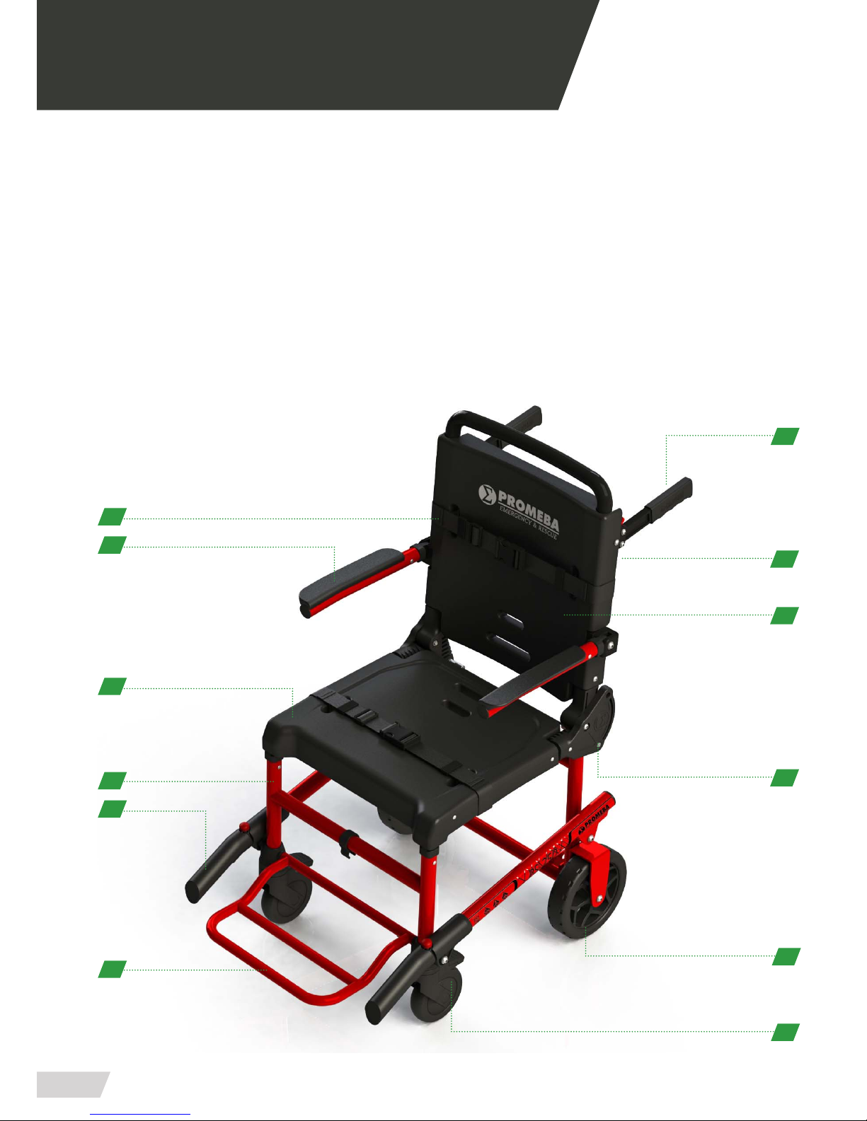
03.1 General elements of CHAIR PS-250
1. Tubular structure in painted aluminum
2. Folding armrest with padding
3. Adjustable belts on legs and chest
4. Thermoformed ABS seat and backrest
5. 5 position telescoping handles
6. Integrated foldable tubular footrest
7. Swivel and lockable wheels with brake
8. Rear wheels of large diameter
9. Unique folding system on the market
10. Measures suitable for bulky people
11. Specic anchors for the track module
12. Lockable grips on the backrest
03 OPERATION
7
9
1
2
8
5
12
10
3
4
6
11
USER GUIDE //
CHAIR PS-250 + POWER TRACK PA-260 + LOCKING SYSTEM PA-270
Review 01/17
15
03.2 Elements of the manual system
CHAIR PS-250
Tubular structure in painted aluminum
Thermoformed ABS seat and backrest
Swivel and lockable wheels with brake
Foldable arm rests with padding
Double position telescopic handles
Large diameter rear wheels
Adjustable belts on legs and chest
Integrated folding tubular footrest
Unique folding system on the market
1
4
7
2
5
8
3
6
9
Suitable measures for large people Specic anchors for the track unit Lockable backrest grips
10 11 12
Ø200mm
470mm
x4
“PULL”
USER GUIDE //
CHAIR PS-250 + POWER TRACK PA-260 + LOCKING SYSTEM PA-270
Review 01/17
16
03 OPERATION
“TIRAR”
“TIRAR”
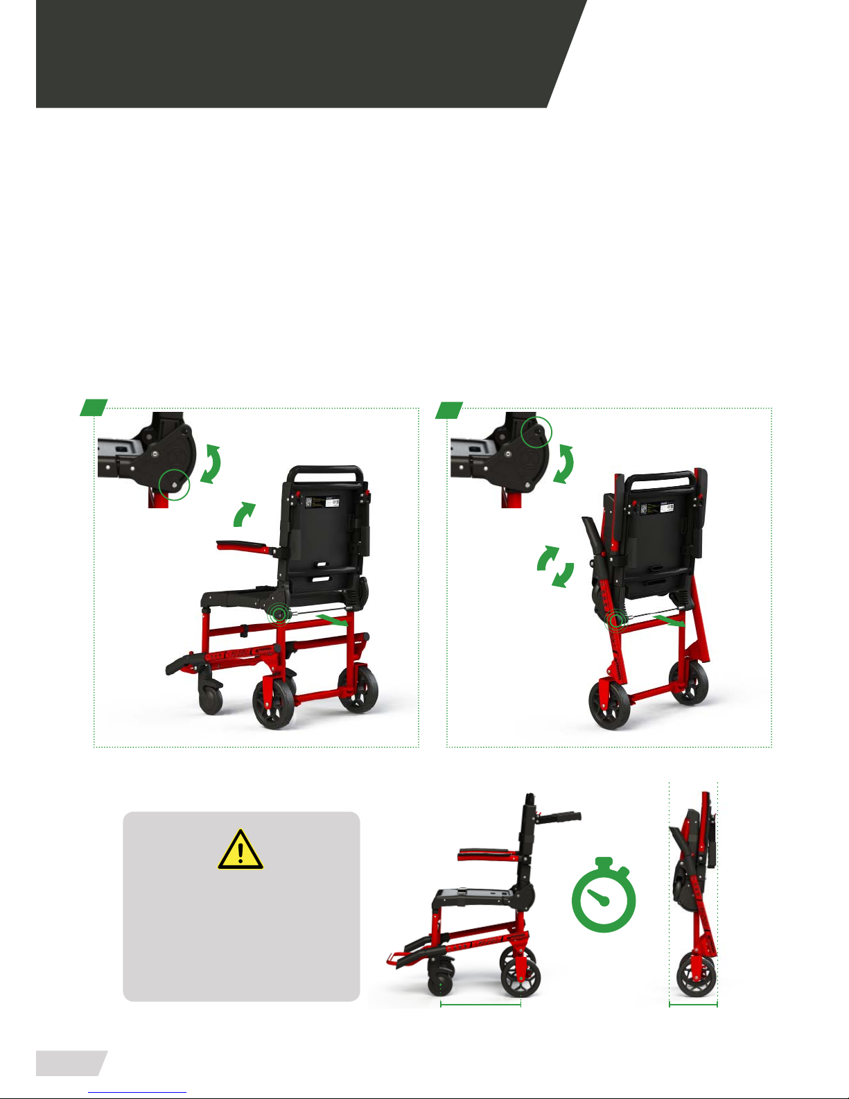
ONLY 2
SECONDS
22 CM40 CM
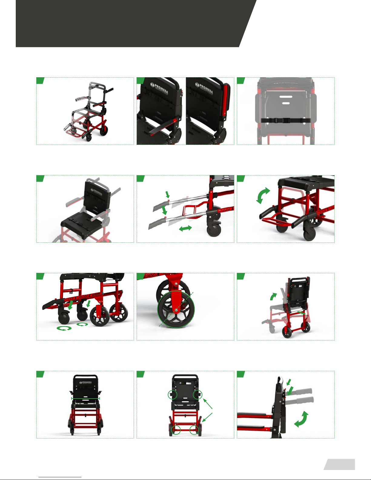
THE FRONT WHEELS OF THE CHAIR AND
ALL HANDLES SHOULD
REMAIN FOLDED AND LOCKED WHEN
IS OPERATED
FOLDING / DEPLOYING THE CHAIR.
OTHERWISE, YOU COULD DAMAGE TO
IMPORTANT ELEMENTS OF THE CHAIR.
03.3 Folding and unfolding the chair
PS-250
To fold the chair locate the unlocking cable on the back of the backrest, with one hand holding the chair
and one foot in the lower tube that joins the wheels, pull the cord toward you and bring the chair closer
to the oor so that the seat approaches the backrest. When the chair is completely folded, the locking
shelves must be in the locked position.
To unfold the chair follow the process in reverse and make sure that the tubes return to their natural loc-
king position.
12

USER GUIDE //
CHAIR PS-250 + POWER TRACK PA-260 + LOCKING SYSTEM PA-270
Review 01/17
17
03.4 Engaging and disengaging operation of track system
PS-250 + PA-260
First, place the track in an extended position, reclining on the tread
bands as shown in gure 1.
With the chair unfolded, bring the lower hooks of the chair closer
to the track, so that they are aligned with the track anchors, slightly
lifting the chair attach the lower anchors as shown in gure 2.
Then, turn the chair on the power track, with a dry blow, you should
hear a CLACK sound and the coupling will have been produced co-
rrectly, see image 3.
To end, lift the assembly and close the track so that the assembly is
according to the image 4.
For the decoupling process, pull the cable located at the top of the
track and it will be released.
03 OPERATION
3
2
1
4
2
112
DURING THE OPERATION OF THE COUPLING AND DISCOUPLING OF THETRACK, THE CHAIR SHALL
REMAIN AT ALL TIMES WITHOUT ANY PATIENT AND ON A SURFACE AS FLAT AS POSSIBLE.
IF NOT, BOTH THE PATIENT AND PERSONNEL MAY RESULT IN WOUNDS AND MAY RESULT IN DA-
MAGED IMPORTANT PRODUCT ELEMENTS.
“CLACK”

USER GUIDE //
CHAIR PS-250 + POWER TRACK PA-260 + LOCKING SYSTEM PA-270
Review 01/17
18
03 OPERATION
03.5 General elements of TRACK PA-260
1. Handle coated with non-slip cover
2. Telescopic handle adjustable system
3. Quick coupling system chair-track
4. Tubular structure in painted aluminum
5. System adjustable to all stairs
6. Possibility of charging with external charger
7. Integrated charging system (with PA-270 support)
8. Roll-over transport wheels
9. High power LED side lighting
10. Built-in belt tensioner system
11. High stability thanks to its special width
12. Central touch control panel
11
10
2
3
1
7
5
4
6
9
8
12

USER GUIDE //
CHAIR PS-250 + POWER TRACK PA-260 + LOCKING SYSTEM PA-270
Review 01/17
19
03.6 Elements of the manual system
TRACK PA-260
Handle coated with non-slip cover
Tubular structure in painted aluminum
Integrated loading system (with PA-270 anchor)
Telescopic handle adjustable system
Adjustable system to all stairs
Roll-over transport wheels
Fastener locking system between chair and track
Possibility of charging with charger device
Powerful LED lighting on both sides
1
4
7
2
5
8
3
6
9
Built-in belt tensioner system High stability thanks to its special width Touch control panel in the middle
10 11 12
340mm
“PULL”
USER GUIDE //
CHAIR PS-250 + POWER TRACK PA-260 + LOCKING SYSTEM PA-270
Review 01/17
20
03 OPERATION
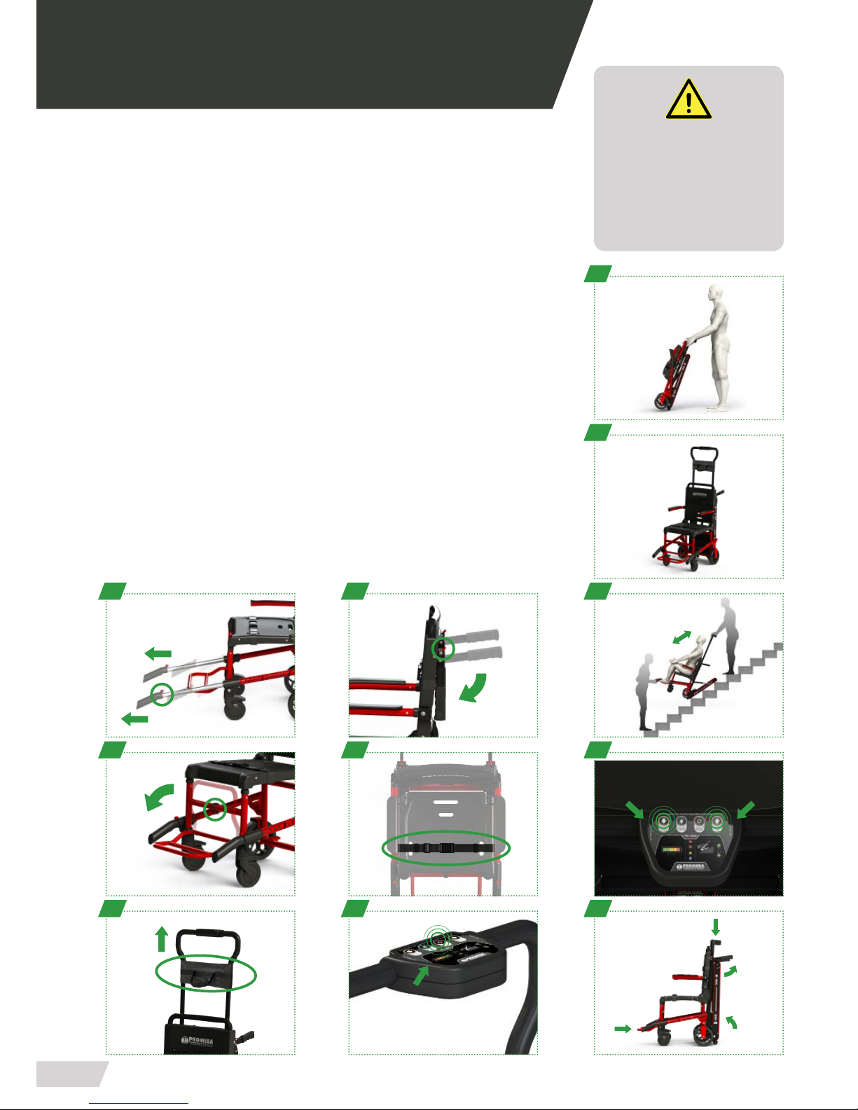
03.7 Operation of up and down stairs of the track system
Starting from the transport position and always with a minimum of two sanitary ope-
rators:
UP
· Attach the chair to the track as explained in section 03.7
· Extend the telescopic handles of the chair (A)
· Fold the backrest handles (B)
· Extend the footrest once the patient is sitting (C)
· Fasten the patient with the two belts supplied (D)
· Fix the patient’s head using the immobilizer located on the track (E)
· Set the track to“stand by” by pressing the ON / OFF button on the control panel (F)
· Approach the chair to the base of the ladder and gently recline the track drive above
the rst steps of the ladder.
· The second operator must extend the telescopic handles before starting the ride and
accompany at all times during the course (3)
· Press the“UP” button to go up the stairs (4)
· Once the section of the stairs is nished, it is very important to fold all the necessary
elements during the plane transfer (5)
DOWN
· The operator in front of the patient should place the chair at the beginning of the
ladder, should assist the inclination of the track (4)
· Press the“DOWN” button to go down the stairs (4)
A
C
3
2
1
4
5
B
D
FE
THE PATIENT SHOULD STAY FIXED AT
ALL TIMES WHEN THE LIFT UP / DOWN IS
OPERATED.
NOT PERMITTED IN ANY CASE
MOBILIZE PATIENTS WITHOUT COMPL-
YING WITH ALL THE SAFETY MEASURES
ESTABLISHED.
ON/OFF
ON/OFF
UP/DOWN
UP/DOWN
This manual suits for next models
2
Table of contents
Other Promeba Wheelchair manuals


