PROMETHEUS MR-20 Manual

52_075aEN
MR-20 Operator’s Guide
Copyright © 2011
The Prometheus Group
One Washington Street, Suite 303
Dover, New Hampshire 03820
FOR ASSISTANCE, CALL YOUR LOCAL SALES REPRESENTATIVE, DISTRIBUTOR, OR
THE PROMETHEUS GROUP
AT
800.442.2325 IN THE U.S. AND CANADA OR 603.749.0733 INTERNATIONAL. FOR TELEPHONE TECHNICAL SUPPORT
CALL 800.272.8492 IN THE U.S. AND CANADA OR 603.742.6053 INTERNATIONAL.
WEBSITE: www.theprogrp.com E-MAIL: info@theprogrp.com

MR-20™ USB Operator’s Guide
Page 2 of 39
w
ww
ww
w.
.t
th
he
ep
pr
ro
og
gr
rp
p.
.c
co
om
m
CONTENTS
NOMENCLATURE 4
SERVICE INFORMATION 4
TECHNICAL SUPPORT 4
INDICATIONS FOR USE 5
CONTRAINDICATIONS 5
Cautions 5
Warnings 6
CHAPTER 1: PHYSICAL-MECHANICAL OVERVIEW 7
Physical 7
The Front Panel
7
The Rear Panel
7
The Top panel
8
Mechanical 9
Connecting the Pathway™ Preamplifier Cables
9
Pathway Adapter
10
Intracavity Vaginal/Rectal EMG/Stimulation Sensors
10
24” Electrode Lead Wire Set
11
CABLE CONNECTION FOR PRACTICE SESSION 12
CABLE CONNECTIONS 12
CHAPTER 2: 14
OPERATION 14
Start-up Display 14
MR-20 Overview of Features and Operation: 15
Running Training Sessions 17
Continuous Mode
17
Work/Rest Mode
17
Training Session 19
SETTING A GOAL 19
Selecting WORK/REST MODE 20
RUNNING SESSIONS 21
VIEWING A SESSION 21
CLEARING ALL SESSIONS 21
Setting the Feedback Mode 22
Feedback Modes 22
Above and Below Goals 23
Changing the Goal Value 23
Max Display Mode 24
Ratio Display Mode 24
Special Functions Mode 25
Patient Data Menus 25
Reviewing Data 26
Reviewing the Current Session Data 26
Reviewing Stored Session Data 27
No Stored Data 28
Clearing Data 28
Setup Menus 28
Session Timing 29
Working with a Functional Stimulator 30

MR-20™ USB Operator’s Guide
Page 3 of 39
w
ww
ww
w.
.t
th
he
ep
pr
ro
og
gr
rp
p.
.c
co
om
m
Stim Setup 31
Stim Timing 31
Stim Relay 32
Stimulator Activation 32
Lock Mode 33
Response Time 34
Special Start-up Modes 34
Demonstration Mode
34
Custom Settings Mode
35
Using the MR-20 with a Computer 35
Installing Software
35
Connecting MR-20 to the computer
36
Saved Session Summary 37
Technical Specifications 38
STANDARD WARRANTY SERVICE AGREEMENT 39
2011 The Prometheus Group. All rights reserved. This document contains confidential and proprietary information that is the property of The
Prometheus Group, Inc. and is protected by the copyright laws of the United States, international copyright treaties, and all other applicable national
laws. Any unauthorized use, reproduction or transfer of any information in this document is strictly prohibited. This document contains information
regarding technology that is protected under one or more United States patents and other pending United States and foreign patents. The
Prometheus Group logo and combinations thereof, Prometheus, Pathway, and DUO are trademarks of The Prometheus Group, Inc., One Washington
Street—Suite 303, Dover, NH 03820. All other brand and product names are used for identification only and are the property of their respective
holders. Specifications are subject to change without notice. Printed in U.S.A.

MR-20™ USB Operator’s Guide
Page 4 of 39
w
ww
ww
w.
.t
th
he
ep
pr
ro
og
gr
rp
p.
.c
co
om
m
N
NO
OM
ME
EN
NC
CL
LA
AT
TU
UR
RE
E
In this Operator’s Guide, NOTES, CAUTIONS, and WARNINGS are included, which have the following
implications:
NOTE: A procedural emphasis - usually something regarding preparation for a process or a
reminder that some bit of information recorded here will be used later for another purpose
CAUTION: A hazard to a piece of equipment or property – for example, potential for an
electrical short, water damage, or some other danger to the equipment but not the operator or
patient. Can also be a reference to HIPAA or other medical legal requirement.
WARNING: A hazard to a person - a potential danger to the operator or patient such
as electrical shock or some other potential danger.
WARNING: There are no serviceable parts within this device. The user should not
attempt to service the instrument beyond that described in the MR-20 Operator’s Guide.
Refer all other servicing to qualified service personnel. Please call 1-800-272-8492 in
the U.S.A. and Canada, or +1 (011) 603-742-6053 international, or e-mail
S
SE
ER
RV
VI
IC
CE
E
I
IN
NF
FO
OR
RM
MA
AT
TI
IO
ON
N
support@theprogrp.com
The instrument should be serviced by qualified service personnel when:
•Any cable, cord, or plug has been damaged.
•The instrument does not appear to operate normally or exhibits a marked change
in performance.
•The instrument has been dropped, or the casing is damaged.
•Fluid has been spilled on the instrument, or it has been immersed, and it appears
that fluid has entered the housing.
T
TE
EC
CH
HN
NI
IC
CA
AL
L
S
SU
UP
PP
PO
OR
RT
T
To contact The Prometheus Group Technical Support for assistance: Telephone: 800-272-
8492 U.S.A. and Canada; +1 (011) 603-742-6053 international; e-mail:
support@theprogrp.com. Technical Support Representatives are available to assist you
between 9:00 a.m. and 5:00 p.m., Eastern Time.

MR-20™ USB Operator’s Guide
Page 5 of 39
w
ww
ww
w.
.t
th
he
ep
pr
ro
og
gr
rp
p.
.c
co
om
m
I
IN
ND
DI
IC
CA
AT
TI
IO
ON
NS
S
F
FO
OR
R
U
US
SE
E
Surface electromyography is a safe and effective technique for relaxation training and muscle re-
education.
Using internal sensors such as the Pathway Vaginal EMG Sensor:
EMG biofeedback is a safe and effective technique for the assessment and treatment of pelvic floor
dysfunction, monitoring the performance of Kegel exercises. The pelvic floor muscles include the
Levator Ani group as well as the pubococcygeus (PC), ileococcygeus, and coccygeus. These are
skeletal muscles which respond to re-education, strengthening, endurance building, and relaxation.
Conditions that can be assessed or treated using this technique include: stress incontinence, mixed
incontinence, and urge incontinence.
C
CO
ON
NT
TR
RA
AI
IN
ND
DI
IC
CA
AT
TI
IO
ON
NS
S
Do not use this device for treatment of incontinence in the presence of any bladder infection,
vaginal infection, or during pregnancy.
C
Ca
au
ut
ti
io
on
ns
s
Prior to using this device, be sure to read the Pathway Device Operator’s Guide for
installation, maintenance, cleaning, technical data, service, and warranty information.
Federal law (USA) restricts this device for sale by or on the order of a licensed medical
practitioner, licensed by law in the state in which they practice.
Federal law (USA) restricts this device for sale by or on the order of a physician when used
for the treatment of incontinence.
Use only electrodes from The Prometheus Group with your Pathway surface EMG device.
Any other electrode may not be compatible with the Pathway device.

MR-20™ USB Operator’s Guide
Page 6 of 39
w
ww
ww
w.
.t
th
he
ep
pr
ro
og
gr
rp
p.
.c
co
om
m
W
Wa
ar
rn
ni
in
ng
gs
s
This device is not intended for use with anesthetic gases mixed with air, oxygen or
nitrous oxide. Danger of electrical ignition.
Be sure to read this operator’s manual before using this device.
Use only electrodes from The Prometheus Group with your Pathway device. Any other
electrodes may not be compatible with the Pathway device.
Do NOT immerse any part of this device in any fluid.
To reduce the risk of electrical shock, do NOT connect any preamplifier, lead wire, electrode,
or any other component to a wall outlet.
Do NOT leave electrodes attached when device is not in use.
To reduce the risk of electrical shock, do NOT open the instrument’s housing. Refer servicing
to qualified personnel only.
Disassembly of equipment by unauthorized personnel will void the instrument’s warranty.
The following practices may be dangerous and void any guarantee(s) and obligations for The
Prometheus Group: (1) The device is not used according to the enclosed manuals and other
accompanying documentation; (2) The device is modified by persons other than The
Prometheus Group Service Technicians; (3) Do not use accessories, consumables and
components not supplied or approved by The Prometheus Group.
Use only batteries with this device, do not use any type of line-powered adapter.
For the treatment of incontinence do not attempt to use this device concurrently with
stimulation being supplied from an electrical muscle stimulator.
Equipment & Accessories
Before using the MR-20 for the first time, carefully open the packing carton and confirm that all
equipment and accessories listed below are included and agree with the packing List/Invoice. If there
are questions about the contents or you wish to order additional supplies, call Customer Service, Toll-
Free: 1-800-442-2325 in the U.S.A. and Canada, +1 (011) 603-749-0733 international, or Fax: 1-
603-749-0511. Customer Service Representatives are on duty between 9:00 a.m. and 5:00 p.m.,
Eastern Time.
Contents
The Pathway MR-20 kit contains the following items:
•The Pathway MR-20 module
•Two preamplifier cables for EMG A & EMG B
•One USB cable
•One 9 volt alkaline battery
•One sample package of 6750 electrodes
•One carrying case
•Operator's Manual
MR-20™ USB Operator’s Guide
Page 7 of 39
w
ww
ww
w.
.t
th
he
ep
pr
ro
og
gr
rp
p.
.c
co
om
m
C
CH
HA
AP
PT
TE
ER
R
1
1:
:
P
PH
HY
YS
SI
IC
CA
AL
L
-
-M
ME
EC
CH
HA
AN
NI
IC
CA
AL
L
O
OV
VE
ER
RV
VI
IE
EW
W
P
Ph
hy
ys
si
ic
ca
al
l
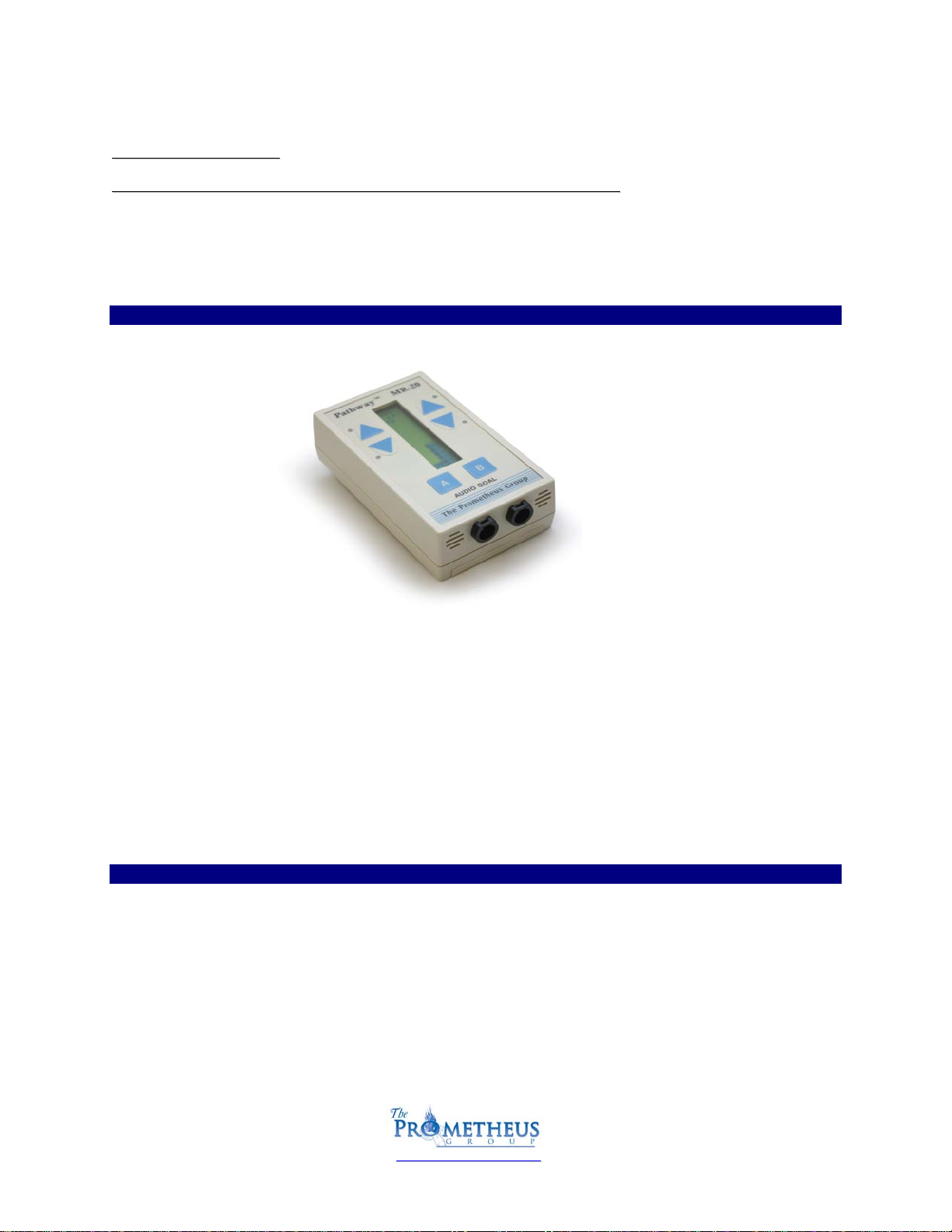
THE FRONT PANEL
The example pictured above is the Pathway™ MR-20. Note input channels A & B.
EMG A: Primary EMG channel. Input for the Pathway™ Preamplifier (part# 2583).
EMG B: Secondary EMG channel or accessory muscle channel. Input for Pathway™ Preamplifier
(part# 2583).
•A two line, dual channel supertwist LCD to display channel options, moving bar graphics, goal level,
goal direction and, microvolt levels
•Four LEDs to enhance goal success
•Two up and down arrow keys to position the goal arrow on the LCD for each channel, and
•An "A" and "B" key to define EMG A and B goal type, direction and control special functions
THE REAR PANEL
On the rear of the unit:
A clip for attaching the MR-series unit to belt or clothing.
9 volt battery compartment (the unit’s serial number is located inside)
To install or change the battery simply press down on the designated area and slide the cover in the
direction indicated. Place the battery in the compartment, noting orientation of battery terminals
and replace the cover, snapping firmly into place. Either a disposable or rechargeable battery may be
used. If using a disposable, an alkaline battery is recommended for longer life. A fresh alkaline
battery will have 20-25 hours of useful life.
MR-20™ USB Operator’s Guide
Page 8 of 39
w
ww
ww
w.
.t
th
he
ep
pr
ro
og
gr
rp
p.
.c
co
om
m
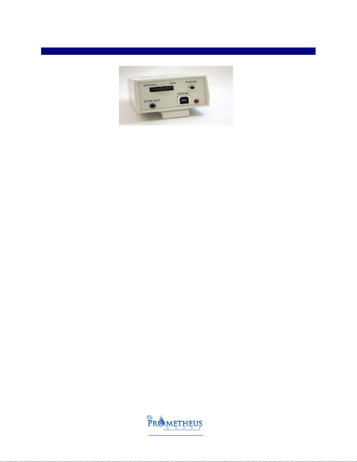
THE TOP PANEL
Power On/Off Rotary Switch:
The thumbwheel switch turns the power on and off and adjusts the volume to the Pathway™ Clinical
unit. Power the MR-20 device on by rotating the switch clockwise, power off by the MR-20 device by
rotating the switch counter clockwise. Powering the MR-20 device on will activate the 4 LEDs in
sequence, sound a tone which can be used to adjust the volume level, and then the display becomes
active.
Phone:
This output allows the user to connect an optional headset with a mono mini plug and will allow the
audio feedback to be heard only by the person wearing the headset.
Stim Out:
This output will accept any functional stimulator that has an accessory or manual input jack for
activating EMG controlled stimulation. A Functional Stimulator Interface Cable connects between
the Pathway MR-20 and the stimulator which is available from The Prometheus Group.
Serial (Computer Interface):
Interfaces the Pathway™ MR-series unit to the laptop or desktop computer using the provided USB
cable.
Red LED:
Indicates that a serial connection has been established via the USB cable.
MR-20™ USB Operator’s Guide
Page 9 of 39
w
ww
ww
w.
.t
th
he
ep
pr
ro
og
gr
rp
p.
.c
co
om
m
M
Me
ec
ch
ha
an
ni
ic
ca
al
l
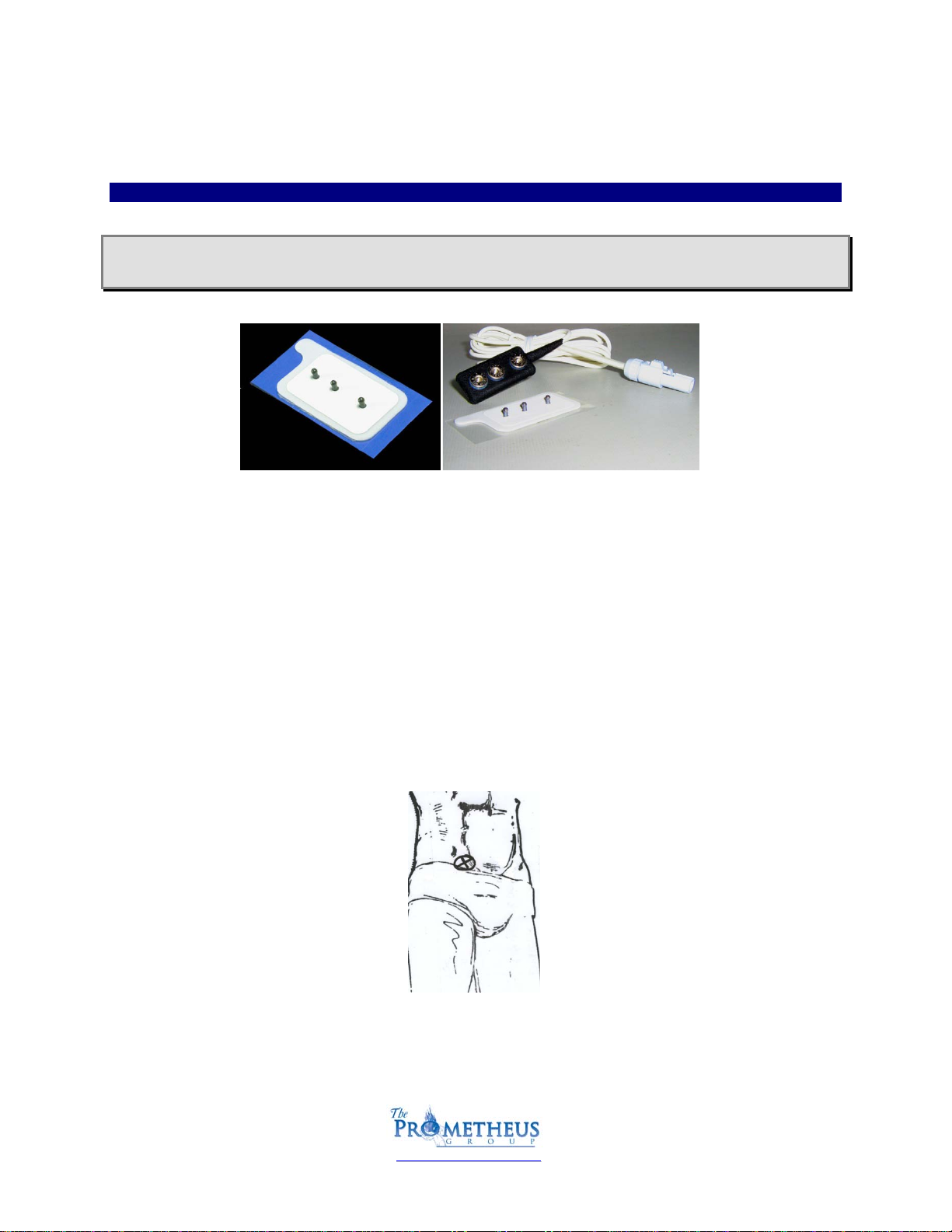
CONNECTING THE PATHWAY™PREAMPLIFIER CABLES
Note: The two Pathway™ Preamplifier (part# 2583) cables are color coded with white and gray
cable to distinguish which is EMG A or EMG B. Either preamplifier can be used for EMG A or EMG B.
Figure . Pathway Electrode (left). Pathway Electrode with white Pathway Preamplifier (right).
1. Primary and secondary muscles are monitored by placing the active electrodes over the bulk
of the muscle. The Pathway™ Preamplifier (part# 2583) has three female snaps” two labeled
ACT (active) and one labeled GND (ground). Prepare the skin with an alcohol pad to avoid
high impedance artifact. Wipe dry with a tissue or cloth. Snap the Pathway™ Preamplifier
(part# 2583) onto one of the Pathway™ Electrodes (part# 6750) taking care to orient the
snaps correctly. Verify all three snaps are secure. Carefully remove the backing of the
Pathway™ (part# 6750) Electrode and place the two labeled ACT (active) over the bulk of the
muscle with the length of the electrode parallel with the muscle fibers. Make certain the
Pathway™ Preamplifier (part# 2583) cable is fully seated into EMG A/EMG B input
channel(s).
2. Accessory Muscles such as Abdominals, Leg Adductors and Gluteals are commonly monitored
by placing the active electrodes over the bulk of the muscle. In the example below the
Pathway™ Electrode (part# 6750) has been placed on the patient’s right side of the
abdomen, just above the pubic hairline.
Positioning the Patient Electrodes on the accessory muscle.

MR-20™ USB Operator’s Guide
Page 10 of 39
w
ww
ww
w.
.t
th
he
ep
pr
ro
og
gr
rp
p.
.c
co
om
m
PATHWAY ADAPTER
This adapter allows EMG A to accept the intracavity sensors or external pelvic muscle electrode lead
wire sets for incontinence applications. Open the Velcro sleeve, match the female snaps on the end of
the Pathway™ Preamplifier (part# 2583) cable with the male snaps of the Pathway™ Adapter (part#
3660), connect and re-wrap the Velcro sleeve. Note the six pin mini din connector input at the end of
the Pathway™ Adapter (part# 3660).
INTRACAVITY VAGINAL/RECTAL EMG/STIMULATION SENSORS
Pathway 6330 Vaginal Sensor Pathway 6340 Rectal Sensor
Internal: Connect either the Pathway 6330 Vaginal EMG/Stimulation Sensor or the Pathway
6340 Rectal EMG/Stimulation Sensor into the Pathway™ Adapter (see previous image). Make
certain orientation of connector matches input jack, push firmly (do not twist). Refer to the
instructions for use enclosed with each sealed sensor bag.
Note: Do not use accessories, consumables and components not supplied or approved by The
Prometheus Group. Using these items may result in inaccurate readings, miss-diagnosis, or
possible damage to your unit and void your unit’s warranty.

MR-20™ USB Operator’s Guide
Page 11 of 39
w
ww
ww
w.
.t
th
he
ep
pr
ro
og
gr
rp
p.
.c
co
om
m
24” ELECTRODE LEAD WIRE SET
24” Electrode Lead Wire Set (part# 5328) Easytrode™ Pregelled electrodes (part# 6801)
Snap the two red and one green lead wires onto the Easytrode™ Pregelled electrodes (part# 6801).
Remove the Easytrode™ Pregelled electrodes (part# 6801) individually.
As shown in the example below place the two red (active) lead wires at the 4 and 10 o’clock positions
around the anus. Place the green (reference/ground) lead wire over the ischial tuperosity or buttocks
muscle. Make certain orientation of 24” electrode lead wire connector matches Pathway™ Adapter
input jack, push firmly (do not twist).
Positioning the Patient Electrodes on the primary muscle.
MR-20™ USB Operator’s Guide
Page 12 of 39
w
ww
ww
w.
.t
th
he
ep
pr
ro
og
gr
rp
p.
.c
co
om
m
C
CA
AB
BL
LE
E
C
CO
ON
NN
NE
EC
CT
TI
IO
ON
N
F
FO
OR
R
P
PR
RA
AC
CT
TI
IC
CE
E
S
SE
ES
SS
SI
IO
ON
N
•Connect gray preamp (Patient Cable) to channel “A”.
•Snap Pathway Electrode onto the black molded end (with three snaps).
•Place the Electrode on your flexor muscle of forearm.
(parallel with the muscle fibers; long edge of electrode will be same direction as arm).
Place on the “Belly” of the muscle.
Also see Cable Connection illustrations.
•Rest your target muscle (arm).
The channel “A” bargraph should read 5 or under. (2 or 3 is not uncommon)
•Contract your muscle.
The reading on the bargraph should increase.
The continuous mode could be used to check a patients’ Resting Baseline by instructing the patient to
relax and reading the bargraph.
C
CA
AB
BL
LE
E
C
CO
ON
NN
NE
EC
CT
TI
IO
ON
NS
S
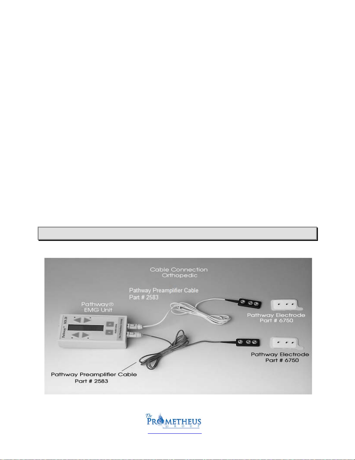
Use illustrations to connect cables, electrodes and accessories.
Choose from the following configurations:
1. Orthopedic (see example below)
2. Continence: Internal Sensor (see example on the following page)
3. Continence: External Pelvic Floor Monitoring (see example on the following page)
NOTE: Illustrations can also be helpful for part identification and re-order numbers.


MR-20™ USB Operator’s Guide
Page 14 of 39
w
ww
ww
w.
.t
th
he
ep
pr
ro
og
gr
rp
p.
.c
co
om
m
O
OP
PE
ER
RA
AT
TI
IO
ON
N
C
CH
HA
AP
PT
TE
ER
R
2
2:
:
S
St
ta
ar
rt
t-
-u
up
p
D
Di
is
sp
pl
la
ay
y
•Turn the unit ON by turning the Thumbwheel switch clockwise. The thumbwheel switch also
adjusts the volume.
•The MR-20 unit will display
Self Test upon power up.
•After the self test has been completed, 4 LEDs will be activated in sequence, the unit will sound
a tone which can be used to adjust the volume level, and then the display becomes active.
•The MR-20 has two basic operating modes: UNLOCKED and LOCKED. In the UNLOCKED mode the
type of goal, goal direction and goal position can be changed by the user
.
If the Pathway MR-20 is to be used in an unsupervised environment such as the home, it can be
LOCKED so that none of these parameters may be changed. Thus the patient must perform the
preset training protocol. In this case the MR-20 would display -- MODE: LOCKED. Locking and
unlocking the MR-20 is explained in the Special Functions section.
On the display (see above example) the VER: 3,00 refers to the current version of software and the
9.3V to the voltage level of the 9 volt battery. These numbers may be different on your MR-20.
•After a few seconds a screen showing the CURRENT SESSION IS # will appear:
•Unit will then default to its’ “Measurement Mode”.
•The unit is in “Continuous” mode meaning there are no Work/Rest intervals set.
•The unit is ready to measure.
NOTE: The Unit only gives you approx. 3 seconds to view information.
Change the battery if voltage reading is under 8V (unit uses a 9V battery).

MR-20™ USB Operator’s Guide
Page 15 of 39
w
ww
ww
w.
.t
th
he
ep
pr
ro
og
gr
rp
p.
.c
co
om
m
Following this screen there may be a warning screen if the battery voltage is becoming too low. If
message reads "BATTERY LOW! REPLACE SOON!", the battery should be replaced prior to
additional use. The message "BATTERY MUST BE REPLACED!" (as shown below) indicates that the
battery voltage is too low to use at all. If the battery is not replaced at this time the MR-20 may stop
operating during a training session. (Since the battery may also go low during a long session, this
message may appear later during use as opposed to start-up.)
NOTE: If the MR-20 has been turned on and does not work properly, try replacing the battery with a
new one. Verify that battery has correct orientation as well as good connectivity (snug fit) to battery
terminals of the unit.
The internal memory of the MR-20 does not
require the battery. Even if the battery is completely
discharged or removed, the saved training session data will be preserved, as will all LOCKED mode
parameters.
M
MR
R-
-2
20
0
O
Ov
ve
er
rv
vi
ie
ew
w
o
of
f
F
Fe
ea
at
tu
ur
re
es
s
a
an
nd
d
O
Op
pe
er
ra
at
ti
io
on
n:
:
(MR-20 Operation "in a nutshell")
•To Set an A Channel Goal press the A key Repeatedly.
To Change Goal Press the Up and Down Arrows.
•To Set B Channel Goal Press the B key Repeatedly.
To Change Goal Press the Up and Down Arrows.
•To Access Special Functions Menu, Press the A and B keys at the same time.
(for about 4 seconds)
This will accomplish the following five things:
1. Review Data (Push A, A, A) Then use up/down arrows to select session.
2. Clear Data (Push A, A, B, A)
3. Work/Rest mode (Push B, A, A, A) then use up/down arrows
to select Work time, Rest time, and number of sessions.
Session automatically begins.
4. Lock/Unlock (Push B, B, A, (Then A or B)
5. Download (Push A, B)
Notes:
•Turn MR-20 off to save the session. (Session must be at least 1 minute
if in continuous mode).
•When using Work/Rest, set goal first
, then Work/Rest, because session automatically begins.
(if goal is desired).
Use this Overview in conjunction with the flow chart on the following page for a quick reference.


MR-20™ USB Operator’s Guide
Page 17 of 39
w
ww
ww
w.
.t
th
he
ep
pr
ro
og
gr
rp
p.
.c
co
om
m
R
Ru
un
nn
ni
in
ng
g
T
Tr
ra
ai
in
ni
in
ng
g
S
Se
es
ss
si
io
on
ns
s
The Pathway MR-20 can run in two different training session modes, either the CONTINUOUS mode, or
the WORK/REST mode. In the CONTINUOUS mode the Pathway MR-20 will run a single session for up
to one hour, with no interruptions. In the WORK/REST mode the Pathway MR-20 will automatically
prompt and control a predetermined number of alternate work periods and rest intervals.
CONTINUOUS MODE
In the CONTINUOUS mode, which is the normal unlocked startup mode, the Pathway MR-20 will
begin displaying EMG activity with no interruptions. A CONTINUOUS mode training session is defined
very simply: WHEN THE MR-20 IS TURNED ON AND EMG ACTIVITY IS DISPLAYED FOR AT
LEAST ONE MINUTE, A NEW TRAINING SESSION IS SAVED IN MEMORY. A readily distinguished
beep will occur at the end of one minute to indicate this. When the MR-20 is turned off and back on,
the next session will automatically begin. The maximum length of each CONTINUOUS mode training
session is 60 minutes. At the end of this time the MR-20 will beep and the display will be:
TURN THE MR-20 OFF WHEN THIS MESSAGE APPEARS
WORK/REST MODE
In the WORK/REST mode the Pathway MR-20 will begin the session by first displaying a “WORK"
message, making three short beeps, and then displaying EMG activity. At the end of the set work
period, the Pathway MR-20 will display a "REST" message on the screen, make one long beep, and
then return to an active EMG display. During this rest interval the EMG activity is being displayed so
that the resting levels may be observed. However, audio and visual (LED) feedback is not active. The
readings during this time are not included in the session data in any way. The session average, the
maximum values, and the percent success are not affected by anything which occurs during a rest
interval. At the beginning of the work period the Pathway MR-20 will display:

MR-20™ USB Operator’s Guide
Page 18 of 39
w
ww
ww
w.
.t
th
he
ep
pr
ro
og
gr
rp
p.
.c
co
om
m
This message is accompanied by three short beeps from the internal speaker. The message will
shortly disappear and the active EMG will be displayed. At the end of the work period the screen will
show:
This message is accompanied by one long beep from the internal speaker. The message will shortly
disappear and the active EMG will be displayed (so the resting activity can be observed). At the end of
the rest interval the next work period will automatically begin.
The WORK/REST mode has three parameters which can be set to customize the session for each
application. The work period of each trial can be set between 3 and 180 seconds. The rest interval
between trials can be set between 0 and 180 seconds. The number of trials in the WORK/REST
session can be set between 1 and 20.
A WORK/REST mode training session is defined very simply: WHEN THE MR-20 IS TURNED ON
AND THE FIRST WORK PERIOD IS COMPLETED, A NEW TRAINING SESSION IS SAVED IN
MEMORY. This is true even though the full set number of trials were not completed. For example, if
the session were set up to have 10 trials, but the MR-20 was turned off after the end of the seventh
work period, the saved session would include the data obtained for the 7 completed trials. When the
MR-20 is turned off and back on, the next session will automatically begin.
If the set number of trials is completed, the MR-20 will beep and the display will be:
Turn the MR-20 off when this message appears.

MR-20™ USB Operator’s Guide
Page 19 of 39
w
ww
ww
w.
.t
th
he
ep
pr
ro
og
gr
rp
p.
.c
co
om
m
T
Tr
ra
ai
in
ni
in
ng
g
S
Se
es
ss
si
io
on
n
A few seconds after being turned on, the Pathway MR-20 will automatically display EMG activity. For
example:
This is the beginning of a training session. The top line shows the EMG A channel and the bottom
shows the EMG B channel. Each line of the display shows the level of EMG activity in a moving bar
display. In addition there is a digital (numeric) display which also shows the EMG value in µV
(microvolts). The MR-20 is designed to be held either horizontally or vertically. The horizontal
position is appropriate for reading the text on the display, while the vertical position is often used
during training sessions. In the vertical position increasing muscle activity moves the bar up and
decreasing activity moves the bar down.
To observe the operation of the display, connect the EMG preamplifiers to the MR-20 and apply the
electrodes to a convenient area such as the forearms, as described in the section "Attaching the
Preamplifiers". Note how the moving bar display ascends and descends, as the hand and wrist
muscles are contracted and relaxed.
Because EMG is essentially a logarithmic function, this type of scaling is used for the moving bar
display. As a result, the movement of the bar relates directly to the change in muscle activity.
The changing digital numbers represent microvolt (µV) levels of EMG activity and increase when
contracting and decrease when relaxing. The total microvolt scale is 1 to 800 µV RMS.
If the MR-20 is being held horizontally, the digital display is normally at the right side of the display. If the
level of activity is very large and the bar reaches the right, the digital display will automatically shift from
the right to the left, so it does not interfere with the bar.
S
SE
ET
TT
TI
IN
NG
G
A
A
G
GO
OA
AL
L
Press the “A” key.
No Goal Set
will be displayed.
Press the “A” key several times.
Notice that the unit will select (cycle through) all of the goals; No Goal Set, Above Tone, Below Tone,
Above Stim, Below Stim, Max Display, Ratio A/B .
Press the “A” key until the Above Tone goal is selected. (Not Above Stim)
The unit will automatically select the
Above Tone goal in about 3 seconds.

MR-20™ USB Operator’s Guide
Page 20 of 39
w
ww
ww
w.
.t
th
he
ep
pr
ro
og
gr
rp
p.
.c
co
om
m
IMPORTANT: THE UNIT WILL NOW DEFAULT BACK TO MEASUREMENT MODE.
Notice an “Up arrow” appears; This is your “Goal Level” or “Threshold”
You may adjust the goal up or down by pressing the Up or Down Arrow keys.
The goal value will be displayed while setting is being adjusted.
Flex your muscle so that the bar graph deflects above the arrow; notice that the unit will beep
because the goal was successfully achieved.
Press the “A” key (twice) until the “Below Tone” goal is selected.
The unit will now default to “Measurement Mode” and will work the same as the “Above Tone”
example, but the beep will be heard when the lights are below
the threshold. (This could be a success
tone for training someone to relax for example)
Press the “A” key until “No Goal” is selected.
Goals will be shut off.
S
Se
el
le
ec
ct
ti
in
ng
g
W
WO
OR
RK
K/
/R
RE
ES
ST
T
M
MO
OD
DE
E
Press the “A” key and the “B” keys at the same time for approximately 4 seconds.
A= Patient Data B=Setup will be displayed
Press the “B” key (Setup).
Press the “A” key (Timing).
Press the “A” key (Session Timing).
Press the “A” key (Work/Rest).
After 3 seconds you are prompted to change the “Work Period: 10 Seconds”
Select the desired work time by pressing the up or down arrow keys.
After 3 seconds you are prompted to change the “Rest Interval: 10 Seconds”
Select the desired rest time by pressing the up or down arrow keys.
After 3 seconds you are prompted to change the “# Trials” 10.
Select the desired # of trials by pressing the up or down arrow keys.
Unit will default back to Measurement Mode and immediatel
ystart a session prompting patient to
work for (the set amount of seconds) and rest for (the set amount of seconds).
You may have to try this a few times until you learn the equipment. If you have to start over simply wait
for the machine to enter measurement mode and start over.
When the session is complete “END OF SESSION” will be displayed.
Turn the unit off and then turn the unit back on, note the session number has incremented by 1.
Other manuals for MR-20
1
Table of contents
Other PROMETHEUS Fitness Equipment manuals


