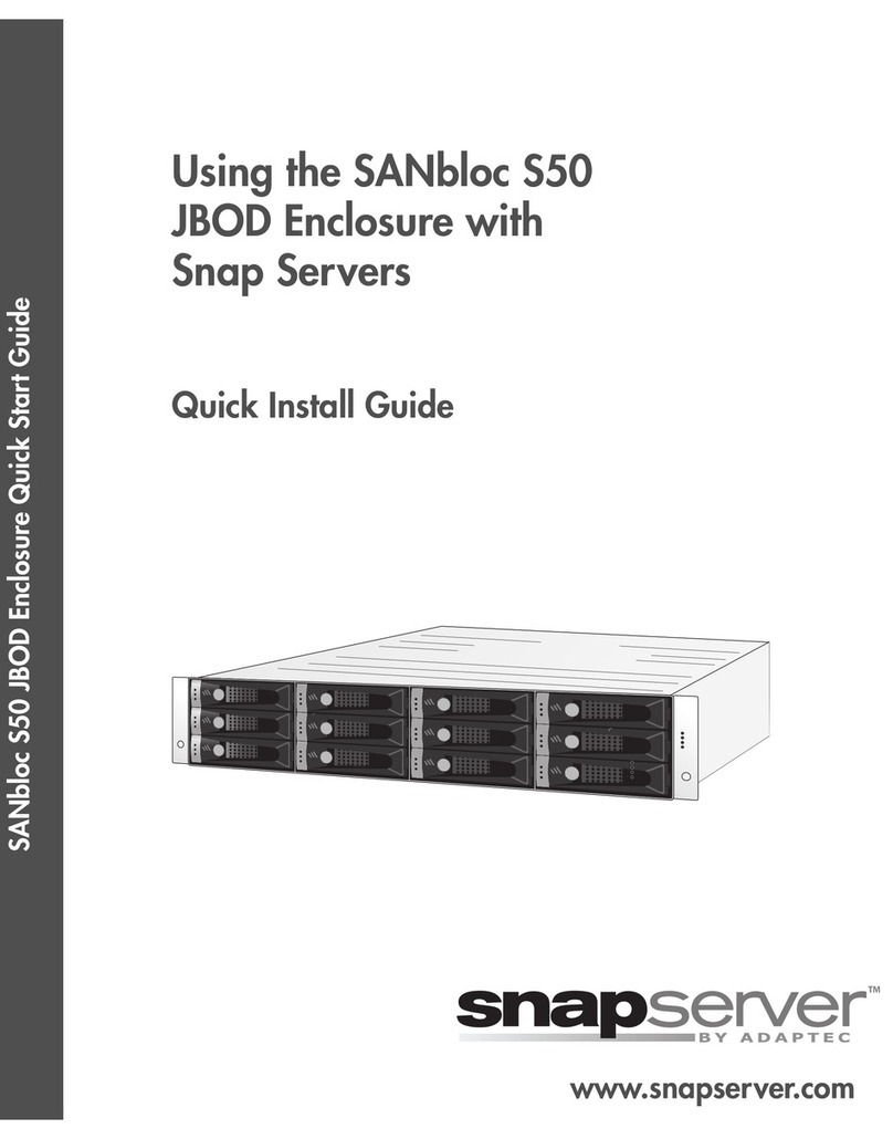
Promise VessRAID 1000f Series User manual

VessRAID
1000f, 1000i, 1000s Series
FC, iSCSI, SAS
Quick Start Guide
Kurzanleitung
Guide de démarrage rapide
Guida Introduttiva
Guía de inicio rápido
Руководство по быстрому
началу работы
クイックスタートガイド
快速安裝手冊
快速安装手册
빠른 시작 안내서
Version 3.0
© 2011 Promise Technology, Inc. All Rights Reserved.

VessRAID 1000f, 1000i, 1000s Series Quick Start Guide
2
Contents
English. . . . . . . . . . . . . . . . . . . . . . . . . . . . . . . . . . . . . . . . . . . . . . . .3
Deutsch . . . . . . . . . . . . . . . . . . . . . . . . . . . . . . . . . . . . . . . . . . . . .48
Français . . . . . . . . . . . . . . . . . . . . . . . . . . . . . . . . . . . . . . . . . . . . .98
Italiano . . . . . . . . . . . . . . . . . . . . . . . . . . . . . . . . . . . . . . . . . . . . .146
Español . . . . . . . . . . . . . . . . . . . . . . . . . . . . . . . . . . . . . . . . . . . . .192
Pусский язык . . . . . . . . . . . . . . . . . . . . . . . . . . . . . . . . . . . . . . . .241
日本語 . . . . . . . . . . . . . . . . . . . . . . . . . . . . . . . . . . . . . . . . . . . . . .290
繁體中文 . . . . . . . . . . . . . . . . . . . . . . . . . . . . . . . . . . . . . . . . . . . .336
简体中文 . . . . . . . . . . . . . . . . . . . . . . . . . . . . . . . . . . . . . . . . . . . .381
한국어 . . . . . . . . . . . . . . . . . . . . . . . . . . . . . . . . . . . . . . . . . . . . . .425

Task 1: Unpacking the VessRAID
3
VessRAID Task List
•Task 1: Unpacking the VessRAID (page 3)
•Task 2: Installing the LCD Panel (Optional) (page 7)
•Task 3: Mounting VessRAID in a Rack (page 9)
•Task 4: Installing Disk Drives (page 12)
•Task 5: Making Data and Management Connections (page 15)
•Task 6: Setting Up Serial Cable Connections (page 29)
•Task 7: Connecting the Power (page 30)
•Task 8: Setting the IP Address (page 34)
•Task 9: Creating Logical Drives with WebPAM PROe (page 40)
•Contacting Technical Support (page 47)
Task 1: Unpacking the VessRAID
The VessRAID box contains the following items:
A Battery Backup Unit (BBU) is optional on the VessRAID subsystem. In the
event of a power failure, the BBU powers the controller cache to preserve any
data it contains.
• VessRAID Unit
•
Quick Start Guide
printed
• RJ11-to-DB9 serial data cable
• Screws for disk drives
(70 pieces for 16-bay, 50 pieces
for 12- and 8-bay)
• 1.5m (4.9 ft) Power cords
(1700 models, 1; 1800 models, 2)
• CD with SNMP files,
Product
Manual
and
Quick Start Guide
in
PDF format
Warning
This is a Class A product. In a domestic environment this product
may cause radio interference in which case the user may be
required to take adequate measures.
Warning
The electronic components within the VessRAID enclosure are
sensitive to damage from Electro-Static Discharge (ESD).
Observe appropriate precautions at all times when handling the
VessRAID or its subassemblies.

VessRAID 1000f, 1000i, 1000s Series Quick Start Guide
4
VessRAID Model Line-up
Caution
• There is a risk of explosion if the battery is replaced by the
incorrect type.
• Dispose of used batteries according to the instructions that
accompany the battery.
Model Interface Number
of Drives
Drive
Carriers
Power
Supplies
Controller
Fans
1840f+ Fibre Channel 16 plus 2 external
1840f Fibre Channel 16 original 2 internal
1840i+ iSCSI 16 plus 2 external
1840i iSCSI 16 original 2 internal
1840s+ SAS 16 plus 2 external
1840s SAS 16 original 2 internal
1830i+ iSCSI 12 plus 2 external
1830i iSCSI 12 original 2 internal
1830s+ SAS 12 plus 2 external
1830s SAS 12 original 2 internal
1820i iSCSI 8 original 2 internal
1740i iSCSI 16 original 1 internal
1740s SAS 16 original 1 internal
1730i iSCSI 12 original 1 internal
1730s SAS 12 original 1 internal
1720i+ iSCSI 8 plus 1 external
1720i iSCSI 8 original 1 internal

Task 1: Unpacking the VessRAID
5
Figure 1. 12-bay VessRAID with the “original” drive carrier design
Figure 2. 12-bay VessRAID with the “plus” drive carrier design
A defective drive may be replaced without interruption of data availability to the
host computer. If so configured, a hot spare drive will automatically replace a
failed drive, securing the fault-tolerant integrity of the logical drive. The self-
contained hardware-based RAID logical drive provides maximum performance in
a compact external enclosure.
Figure 3. VessRAID 1840f+ rear view
Drive Carrier LEDs
Drive Carriers Power and Status LEDs
Drive Carrier LEDs
Drive Carriers Power and Status LEDs
External Fans
SAS RAID ControllerDual Power Supplies

VessRAID 1000f, 1000i, 1000s Series Quick Start Guide
6
Figure 4. VessRAID 1830s+ rear view
Figure 5. VessRAID 1830i rear view
Figure 6. VessRAID 1730s rear view
For a description of the LEDs, see pages 30 and 31.
SAS RAID ControllerDual Power Supplies
External Fans
iSCSI RAID Controller
Internal Fans
Dual Power Supplies
Internal Fans
SAS RAID ControllerSingle Power Supply

Task 2: Installing the LCD Panel (Optional)
7
Task 2: Installing the LCD Panel (Optional)
The LCD panel mounts to the left ear of the VessRAID enclosure.
1. Align the connector on the left bracket of the VessRAID enclosure to the
connector on the back of the LCD panel, as shown in Figure 7.
Figure 7. Align the connectors on the enclosure and the LCD panel
2. Insert the two attaching screws through the holes in the left bracket and into
the threaded holes in the LCD panel, as shown in Figure 8.
Tighten the screws to secure the LCD panel to the bracket.
Cautions
• The LCD panel is NOT a hot-swap device. Be sure the
VessRAID is powered down before you connect or disconnect
the LCD panel.
• You must install the LCD panel before you mount the
VessRAID subsystem in a rack.
Connector on
the LCD panel
Connector on
the enclosure

VessRAID 1000f, 1000i, 1000s Series Quick Start Guide
8
Figure 8. Attaching the LCD panel to the VessRAID enclosure
The LCD screen activates when the VessRAID boots. See “Task 7: Connecting
the Power” on page 30.
Go to “Task 3: Mounting VessRAID in a Rack” on page 9.

Task 3: Mounting VessRAID in a Rack
9
Task 3: Mounting VessRAID in a Rack
The VessRAID subsystem installs to the rack using the available mounting rails.
You can also use your existing rails.
Cautions
• At least two persons are required to safely lift, place, and
attach the VessRAID unit into a rack system.
• Do not lift or move the VessRAID unit by the handles, power
supplies or the controller units. Hold the subsystem itself.
• Do not install the VessRAID unit into a rack without rails to
support the subsystem.
• Only a qualified technician who is familiar with the installation
procedure should mount and install the VessRAID unit.
• Be sure all switches are OFF before installing the VessRAID
unit or exchanging components.
• Mount the rails to the rack using the appropriate screws and
flange nuts, fully tightened, at each end of the rail.
• Do not load the rails unless they are installed with screws as
instructed.
• The rails available for the PROMISE VessRAID unit are
designed to safely support that PROMISE VessRAID unit
when properly installed. Additional loading on the rails is at
the customer’s risk.
• PROMISE Technology, Inc. cannot guarantee that the
mounting rails will support your PROMISE VessRAID unit
unless you install them as instructed.
Note
To lighten the VessRAID enclosure, remove the power supplies.
Replace the power supplies after the VessRAID unit is mounted in
your rack.

VessRAID 1000f, 1000i, 1000s Series Quick Start Guide
10
Figure 9.
A 16-bay VessRAID mounted in a rack with the available rails
To install the VessRAID subsystem into a rack with the available mounting rails:
1. Check the fit of the mounting rails in your rack system.
See page 11, Figure 10.
2. Adjust the length of the mounting rails as needed.
The rear rail slides inside the front rail. The rail halves are riveted together
and use no adjustment screws.
3. Attach the mounting rail assemblies to the outside of the rack posts, using
the attaching screws and flange nuts from your rack system.
Be sure the front rail support is on the bottom facing inward.
The alignment pins fit into the rack holes above and below the attaching
screws.
Use the attaching screws and flange nuts from your rack system. Tighten the
screws and flange nuts according to your rack system instructions.
4. Place the VessRAID subsystem onto the rails.
5. Secure the VessRAID subsystem to the rack.
One screw each side, in the upper hole only. Use the attaching screws and
flange nuts from your rack system. Tighten the screws and flange nuts
according to your rack system instructions.
Vertical Rack Post VessRAID subsystem
Mounting rails mount
outside the rack post
Handles mount
outside the rack post

Task 3: Mounting VessRAID in a Rack
11
Figure 10.Rack mount assembly diagram
This completes rack mounting. Go to “Task 4: Installing Disk Drives” on page 12.
Inside of post
Rack front post
Rail attaching screws
(not included)
Alignment pins
two on each flange
Inside of post
Rack rear post
Front rail Rear rail
Support for
subsystem
Note that only the front rail has a support for the subsystem.

VessRAID 1000f, 1000i, 1000s Series Quick Start Guide
12
Task 4: Installing Disk Drives
The VessRAID subsystems and VessJBOD expansion units support:
• SAS and SATA hard disk drives
• 3.5-inch hard disk drives
For a list of supported physical drives, download the latest compatibility list from
the PROMISE support website.
Number of Drives Required
The table below shows the number of drives required for each RAID level
Drive Slot Numbering
You can install any suitable disk drive into any slot in the enclosure. The diagram
below shows how VessRAID’s drive slots are numbered. Whether you have the
original or plus carriers, the slots are numbered the same.
Slot numbering is reflected in the WebPAM PROe and CLU user interfaces. See
Figures 11, 12, and 13.
Figure 11. 16-bay VessRAID drive slot numbering
Level Number of Drives Level Number of Drives
RAID 0 1 or more RAID 6 4 to 32*
RAID 1 2 only RAID 10 4 or more**
RAID 1E 2 or more RAID 30 6 or more
RAID 3 3 to 32* RAID 50 6 or more
RAID 5 3 to 32* RAID 60 8 or more
* A JBOD expansion unit may be required.
** Must be an even number of drives.
1
5
9
13
2
6
10
14
3
7
11
15
4
8
12
16

Task 4: Installing Disk Drives
13
Figure 12.12-bay VessRAID drive slot numbering
Figure 13.8-bay VessRAID drive slot numbering
Install all of the drive carriers into the VessRAID enclosure to ensure proper
airflow, even if you do not populate all the carriers with disk drives.
Installing Your Disk Drives
To install your disk drives:
1. Remove a disk drive carrier.
2. Carefully lay the disk drive into the drive carrier at the front, so that the screw
holes on the sides line up.
See page 14, Figure 14.
3. Insert the screws through the holes in the drive carrier and into the sides of
the disk drive.
• Install only the counter-sink screws supplied with the VessRAID.
• Install four screws per drive.
• Snug each screw. Be careful not to over-tighten.
4. Reinstall the drive carrier into the VessRAID enclosure.
Repeat steps 1 through 3 until all of your disk drives are installed.
1
5
9
2
6
10
3
7
11
4
8
12
1
5
2
6
3
7
4
8

VessRAID 1000f, 1000i, 1000s Series Quick Start Guide
14
Figure 14.Disk drive mounted in a drive carrier
This completes disk drive installation. Go to “Task 5: Making Data and
Management Connections” on page 15.
Caution
VessRAID supports disk drive hot-swapping. To avoid hand
contact with an electrical hazard, do not remove more than one
drive carrier a time.
Disk drive
mounting screw
mounting screw

Task 5: Making Data and Management Connections
15
Task 5: Making Data and Management Connections
You can configure your VessRAID for:
• Fibre Channel Direct Attached Storage (DAS), see below
•Fibre Channel Storage Area Network (SAN) (page 18)
•iSCSI Direct Attached Storage (DAS) (page 20)
•iSCSI Storage Area Network (SAN) (page 22)
•SAS Direct Attached Storage (DAS) (page 25)
•SAS JBOD Expansion (page 27)
Fibre Channel Direct Attached Storage (DAS)
This arrangement requires:
• A Fibre Channel (FC) interface card in the Host PC
• At least one FC transceiver for each VessRAID subsystem
• A network interface card (NIC) in the Host PC
• A standard network switch
Data Path
The VessRAID controller has two (2) FC Port connectors and one (1) SFF-8088
SAS Expansion Port connector. See page 16, Figure 15.
To establish the data path:
1. Install an FC transceiver into the FC data port on the VessRAID controller.
See page 17, Figure 16.
2. Connect the FC transceiver on the VessRAID controller to the Host PC or
Server.
See also “SAS JBOD Expansion” on page 27.
Important
For a list of supported FC HBAs, Switches and SFPs, download
the latest compatibility list from the PROMISE support website.
VessRAID does not support cascading of multiple RAID
subsystems. Cascading is planned for a future release.
Note
VessRAID Fibre Channel subsystems also have two (2) Ethernet
RJ45 iSCSI Port connectors. See “iSCSI Direct Attached Storage
(DAS)” on page 20 for connection instructions.

VessRAID 1000f, 1000i, 1000s Series Quick Start Guide
16
Management Path
The VessRAID controller has one (1) Ethernet RJ-45 Management Port
connector. See Figure 15.
To establish the management path:
1. Attach one end of an Ethernet cable to the network connector or standard
NIC in the Host PC.
Attach the other end of the Ethernet cable to one of the ports on the standard
network switch.
See page 17, Figure 16.
2. Attach one end of an Ethernet cable to one of the ports on the standard
network switch.
Attach the other end of the Ethernet cable to the Management Port on the
VessRAID subsystem.
If you have multiple VessRAID subsystems, Host PCs or Servers, repeat
steps 1 and 2 as required.
Figure 15.VessRAID 1840f+ data and management ports. 1840f is similar
iSCSI data port 1
Management port
iSCSI data port 2
FC data port 2
FC data port 1
SAS expansion
port (to JBOD)

Task 5: Making Data and Management Connections
17
Figure 16.FC DAS data and management connections
NIC
Host PC or Server Network Switch
VessRAID 1840f+
1840f is similar
Management
Cables
Data Cable FC Data Ports (2)Management Port
FC card

VessRAID 1000f, 1000i, 1000s Series Quick Start Guide
18
Fibre Channel Storage Area Network (SAN)
This arrangement requires:
• A Fibre Channel (FC) interface card in each Host PC
• At least one FC transceiver for each VessRAID subsystem
• A network interface card (NIC) in each Host PC
• A standard network switch
Data Path
The VessRAID controller has two (2) FC Port connectors and two (2) Ethernet
RJ45 iSCSI Port connectors. See page 16, Figure 15.
To establish the data path:
1. Install an FC transceiver into the FC data port on the VessRAID controller.
See page 19, Figure 17.
2. Connect the FC transceiver on the VessRAID subsystem to the FC switch.
3. Connect the FC switch to the FC HBA card in the Host PC or Server.
If you have multiple VessRAID subsystems, Host PCs or Servers, repeat
steps 1 and 2 as required.
See also “SAS JBOD Expansion” on page 27.
Management Path
The VessRAID controller has one (1) Ethernet RJ-45 Management Port
connector. See page 16, Figure 15.
To establish the management path:
1. Attach one end of an Ethernet cable to the network connector or standard
NIC in the Host PC.
Attach the other end of the Ethernet cable to one of the ports on the standard
network switch.
See page 19, Figure 17.
2. Attach one end of an Ethernet cable to one of the ports on the standard
network switch.
Attach the other end of the Ethernet cable to the Management Port on the
VessRAID subsystem.
Note
VessRAID Fibre Channel subsystems also have two (2) Ethernet
RJ45 iSCSI Port connectors. See “iSCSI Storage Area Network
(SAN)” on page 22 for connection instructions.

Task 5: Making Data and Management Connections
19
If you have multiple VessRAID subsystems, Host PCs or Servers, repeat
steps 1 and 2 as required.
Figure 17.FC SAN data and management connections
Host PCs or
Servers
NIC
Network
Switch
FC Switch
VessRAID 1840f+
VessRAID 1840f
FC card
NIC
FC card
Management Cables
Data Cables
FC Data Ports (2)Management Port

VessRAID 1000f, 1000i, 1000s Series Quick Start Guide
20
iSCSI Direct Attached Storage (DAS)
This arrangement requires:
• A Gigabit Ethernet network interface card (GbE NIC) in the Host PC or
Server with iSCSI support in hardware or in software
• A standard network switch
• A network interface connector on the motherboard or network interface card
(NIC) in the Host PC
Configuring a Data Path
The VessRAID controller has four (4) Ethernet RJ45 iSCSI Port connectors. See
page 21, Figure 18.
To establish the data path:
1. Attach one end of an Ethernet cable to the GbE (iSCSI) NIC in the Host PC.
See page 21, Figure 19.
2. Attach the other end of the Ethernet cable to one of the four iSCSI ports on
the VessRAID controller.
If you have multiple VessRAID subsystems, Host PCs or Servers, repeat
steps 1 and 2 as required.
See also “SAS JBOD Expansion” on page 27.
Configuring a Management Path
The VessRAID controller has one (1) Ethernet RJ-45 Management Port
connector. See page 21, Figure 18.
To establish the management path:
1. Attach one end of an Ethernet cable to the network connector or standard
NIC in the Host PC.
Attach the other end of the Ethernet cable to one of the ports on the standard
network switch. See page 21, Figure 19.
2. Attach one end of an Ethernet cable to one of the ports on the standard
network switch.
Attach the other end of the Ethernet cable to the Management Port on the
VessRAID subsystem.
If you have multiple VessRAID subsystems, Host PCs or Servers, repeat
steps 1 and 2 as required.
Note
These instructions also apply to the iSCSI Ports on VessRAID
Fibre Channel subsystems.
Other manuals for VessRAID 1000f Series
2
This manual suits for next models
2
Table of contents
Languages:
Other Promise Enclosure manuals
